








Automotive Sensors & Diagnostics
Oxygen Sensor Guide: Diagnose, Replace and Buy the Right O2 Sensor
Learn how to identify the exact sensor, separate symptoms from proof, verify whether replacement is justified, and confirm fitment before ordering.

Quick answer: does the oxygen sensor actually need replacement?
An automotive oxygen sensor measures oxygen remaining in the exhaust so the engine control system can manage fuel delivery and, depending on sensor position, monitor catalytic-converter performance. Before replacing one, identify the exact bank and sensor position, read all diagnostic trouble codes and freeze-frame data, inspect wiring and connectors, check for intake or exhaust leaks, and compare live data with vehicle-specific service information.
A check-engine light, poor fuel economy, rough running, hesitation, or an emissions-test failure can be consistent with an oxygen-sensor problem, but none of these proves the sensor itself has failed. Buying the correct replacement requires more than matching the thread or wire count: verify OE or validated cross-reference number, year/make/model/engine, emission configuration, upstream/downstream position, sensor technology, connector keying, wire length, and market.
Identify the exact oxygen sensor before testing or ordering
A vehicle may have two, four, or more oxygen sensors. Correctly identifying the target sensor is the first step in both diagnosis and purchasing. Terms such as front, rear, left, and right can be ambiguous because engine orientation, cylinder-bank layout, catalyst placement, and exhaust routing vary by vehicle.
The sensor before the catalytic converter is generally the control sensor. It gives the controller feedback used to correct air-fuel mixture. A sensor after the converter is generally used to monitor converter behavior and provide diagnostic feedback. Modern exhaust systems may have multiple banks, multiple converters, and more than two sensors, so “front” and “rear” are not sufficiently precise purchasing descriptions.
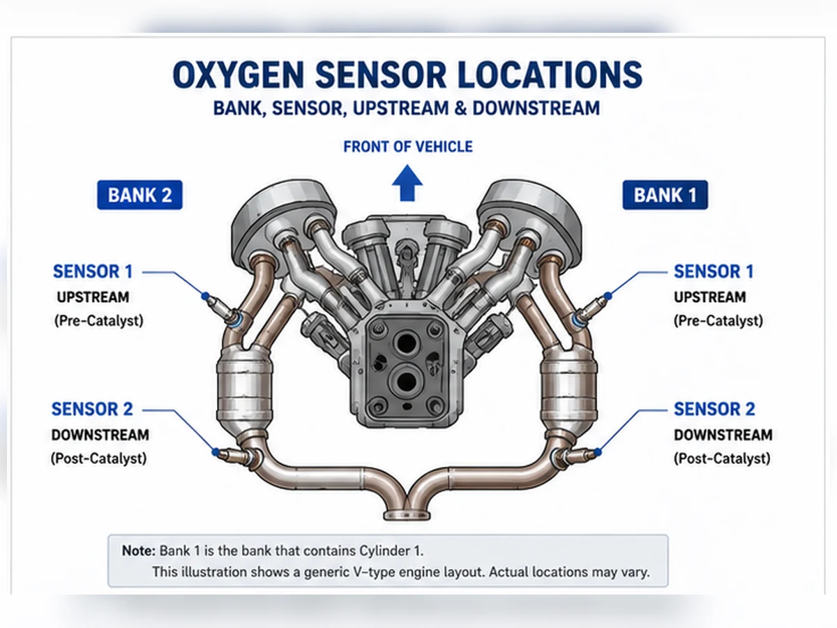
Upstream / pre-catalyst
Usually identified as Sensor 1 for its bank. It has the strongest connection to closed-loop fuel correction, but the exact control strategy depends on the vehicle.
Downstream / post-catalyst
Usually identified as Sensor 2 for its bank. It is commonly used to assess catalyst-system behavior and must not be removed, bypassed, or treated as optional.
Build a minimum sensor identity record
Before a technician tests a sensor—or a buyer requests a quotation—the target component should be defined as a complete identity rather than a loose description such as “rear O2 sensor.” The identity record connects the diagnostic location to the part-selection data.
| Identity field | Why it changes the decision | Weak input to reject |
|---|---|---|
| Year / make / model / engine | Separates engine families, exhaust layouts and control strategies | Vehicle model name alone |
| Market and emissions configuration | Can change catalyst layout, calibration and part number | “Same vehicle worldwide” assumption |
| Bank and sensor number | Defines the monitored exhaust branch and sequence | Left, right, front or rear without a diagram |
| Sensor technology | Determines the valid circuit and signal test | Wire count or connector appearance only |
| OE number or validated cross-reference | Connects the physical part to a cataloged application | Marketplace title without source data |
| Connector, cable and mechanical geometry | Controls electrical fit, routing, heat clearance and installation | Matching thread alone |
Technical source mapping: DENSO troubleshooting guidance identifies cylinder number 1 as the reference for Bank 1 and places Sensor 1 before the catalytic converter in the illustrated V-engine layout. Vehicle-specific service information remains controlling.
Types of oxygen sensors
“Type” can refer to sensing technology, construction, exhaust position, or replacement format. These categories overlap. For example, a direct-fit upstream sensor may be a heated wideband sensor with a planar zirconia element. Do not choose a replacement from only one classification.
| Classification | What it means | Typical role | Buying risk |
|---|---|---|---|
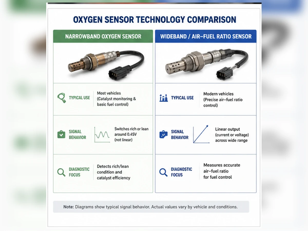
| Zirconia narrowband / step-change | Indicates rich-to-lean transition around stoichiometric operation rather than measuring a broad mixture range linearly. | Common control or monitoring function on many vehicles. | Cannot be substituted for a wideband or air-fuel-ratio sensor merely because the connector or thread appears similar. |
| Titania | Changes electrical resistance with oxygen concentration and uses a different circuit strategy from conventional zirconia sensors. | Found in certain older applications. | Electrical characteristics differ; a zirconia sensor is not an automatic substitute. |
| Wideband / air-fuel-ratio / UEGO | Uses a control cell and pump-current strategy to measure rich and lean operation across a wider range. | Often used as the upstream control sensor in newer engine-management systems. | Calibration, heater control, connector, and electronics must match the application. |
| Heated | Contains an internal heater to reach operating temperature more quickly. | Common on OBD-era vehicles. | Wire count does not by itself identify heater current, sensor technology, or compatibility. |
| Unheated | Relies more heavily on exhaust heat to reach operating temperature. | Older applications. | Do not replace with a heated design unless a validated application catalog explicitly permits it. |
| Direct-fit | Application-specific connector, cable length, routing provisions, and sensor specification. | Preferred for most routine repairs when correctly cataloged. | A catalog error or incomplete YMME/emission data can still produce the wrong part. |
| Universal / splice-in | Requires approved wire-splicing and application-specific installation instructions. | Inventory-consolidation or limited-availability applications. | Wire color, sensor type, heater circuit, reference-air path, sealing method, and local rules must be verified. |
Narrowband versus wideband
A narrowband sensor is primarily useful for identifying which side of the stoichiometric switching point the mixture is on. A wideband sensor can represent a broader rich-to-lean range with greater control resolution. The vehicle controller and sensor form a matched measurement system; replacing one technology with another is not a general upgrade path.
Direct-fit versus universal
A verified direct-fit sensor normally reduces installation variables because the connector, cable length, strain relief, and routing are designed for a defined application. Universal sensors require the correct sensor technology plus an approved connection method. Soldering, crimping, sealing, or routing a universal sensor incorrectly can create high resistance, reference-air contamination, heater faults, or heat damage.
Technical source mapping: NTK / Niterra oxygen-sensor guidance distinguishes zirconia, titanium-dioxide and broad/wideband/linear sensor families. This supports the page’s warning that sensing technology and diagnostic method must be matched rather than inferred from thread, connector appearance or wire count.
Bad oxygen sensor symptoms—and what they do not prove
Oxygen-sensor faults often appear as a combination of an illuminated malfunction indicator lamp, fuel-economy change, rough idle, hesitation, poor acceleration, increased emissions, or a failed inspection. The same symptoms can also be caused by intake leaks, exhaust leaks, ignition misfire, fuel-delivery faults, coolant or oil contamination, damaged wiring, poor grounds, or catalyst deterioration.
| Observation | Possible oxygen-sensor relationship | Other checks before replacement |
|---|---|---|
| Check-engine light | Sensor signal, response, heater, or circuit fault may be recorded. | Read all codes, freeze frame, pending codes, OEM-specific codes, and monitor status. |
| Poor fuel economy | A biased or slow upstream sensor can affect fuel correction. | Fuel trims, thermostat and coolant-temperature data, intake leaks, fuel pressure, injectors, ignition, and driving conditions. |
| Rough idle, hesitation, or misfire | Incorrect feedback may contribute, but the sensor can also be reporting a real combustion problem. | Misfire counters, plugs/coils, compression, vacuum leaks, injectors, mass-airflow data, and exhaust leaks. |
| P0130–P0167 family code | May concern sensor circuit, heater, signal range, or response. | Wiring continuity, power/ground, fuse, connector condition, exhaust leak, contamination, and service-manual test sequence. |
| P0420 or P0430 | Oxygen-sensor data is used by the catalyst monitor, but the code does not prove the sensor is defective. | Catalyst condition, exhaust leaks, fuel control, misfire history, sensor response, software updates, and manufacturer diagnostics. |
| Failed emissions inspection | A sensor or heater fault may prevent a monitor from completing or increase emissions. | Readiness status, all stored/pending codes, recent battery disconnect or code clearing, and the complete emissions-control system. |
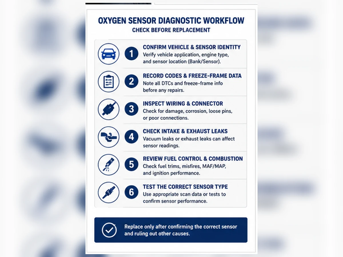
Diagnose before replacing: a six-step verification workflow
- Identify the vehicle configuration. Record year, make, model, engine, fuel type, emission label, VIN breakpoint when applicable, and target sensor position.
- Scan the complete system. Capture stored, pending, and permanent codes, freeze-frame data, fuel trims, readiness monitors, and relevant OEM data PIDs before clearing anything.
- Inspect the basics. Check the sensor connector, harness routing, heat damage, corrosion, grounds, heater power, fuses, exhaust leaks, and intake leaks.
- Evaluate the signal correctly. Use the manufacturer’s test method for the actual sensor technology. A conventional narrowband voltage test is not valid for every wideband or air-fuel-ratio sensor.
- Confirm the root cause. Correct fuel, ignition, coolant, oil-consumption, or exhaust problems that could damage the new sensor or cause the same code to return.
Composite scenario: a lean code with a working sensor
Illustrative composite—not a customer case or Sunhyings product test. An upstream sensor remains lean and the vehicle stores a fuel-trim code. Instead of replacing the sensor, the technician checks intake integrity and finds unmetered air. After repairing the leak, fuel trims return toward normal and the sensor responds correctly.
Decision lesson: a functioning sensor can report a real lean condition. The displayed result must be interpreted together with fuel trims, leak testing and combustion data.
Composite scenario: a heater code caused by the vehicle circuit
Illustrative composite—not a customer case or Sunhyings product test. A heater-circuit code returns after an unnecessary sensor replacement. Circuit checks then reveal heat-damaged wiring and missing heater supply at the connector.
Decision lesson: a circuit code names the monitored circuit, not necessarily the failed part. Power, ground, control and harness integrity must be verified first.
Fault codes and live data: evidence, not a parts order
Diagnostic trouble codes identify a monitored system, circuit or operating condition. They are the beginning of a diagnostic process, not a confirmed replacement instruction.
The P0130–P0167 family can include sensor-signal, response, circuit and heater conditions. P0420 and P0430 concern catalyst-system efficiency monitoring; oxygen-sensor data contributes to that monitor, but these codes do not automatically prove that either sensor has failed.
Use an evidence ladder instead of one data point
| Evidence | What it can establish | What it cannot establish alone |
|---|---|---|
| Code description | The monitored circuit, response or system condition | Which physical component is definitely defective |
| Freeze-frame data | The operating conditions when the fault was recorded | Whether the condition is repeatable or the sensor is internally failed |
| Fuel trims and misfire data | Whether the controller is correcting a real mixture or combustion problem | Sensor compatibility or wiring integrity |
| Visual and circuit inspection | Connector, routing, power, ground and obvious exhaust defects | Dynamic sensor accuracy under all operating conditions |
| Sensor-specific response test | Whether the installed sensor responds according to the applicable procedure | The cause of contamination or repeat failure |
| Post-repair verification | Whether the system now operates and monitors correctly | A guarantee against unrelated future faults |
The strongest replacement decision combines several independent findings: correct component identity, intact vehicle-side circuitry, no unresolved leaks or combustion faults, and an applicable test showing that the sensor itself no longer performs correctly.
Replace the sensor now—or continue diagnosis?
| Finding | Replace now? | Why | Next action |
|---|---|---|---|
| Internal heater failure confirmed after circuit checks | Usually | Internal sensor fault has been isolated | Verify the exact replacement |
| Signal bias or slow response confirmed by the correct procedure | Usually | Sensor output no longer meets required behavior | Correct the contamination source and replace |
| P0420 or P0430 only | Not automatically | Catalyst-monitor code is not sensor proof | Complete catalyst-system diagnosis |
| Exhaust leak near the sensor | Not yet | Additional oxygen can distort the reading | Repair the leak and retest |
| Damaged vehicle harness outside the sensor | Not necessarily | The harness may be the root cause | Repair the circuit and verify operation |
| Symptoms without testing | No | Evidence is insufficient | Complete the diagnostic workflow |
Oxygen sensor replacement: planning, safety and post-repair verification
Replacement difficulty ranges from straightforward access in an engine bay to a seized sensor above a hot exhaust system that requires a lift, penetrating treatment, thread repair, or exhaust-component removal. The following is a decision-oriented overview, not a substitute for model-specific service instructions.
- Confirm the exact failed position. Match Bank 1/Bank 2 and Sensor 1/Sensor 2 to the vehicle’s cylinder numbering and exhaust layout.
- Verify the replacement before removal. Compare validated OE/cross-reference data, sensor technology, connector keying, pin count, cable length, thread, hex, protective shield, and application notes.
- Make the vehicle safe. Let the exhaust cool, use approved lifting and support points, wear eye and hand protection, and keep the work area ventilated.
- Disconnect and remove carefully. Release the connector without pulling the wires, note harness routing, and use the appropriate sensor socket or wrench. Avoid damaging the exhaust bung.
- Prepare the threads according to instructions. Many replacement sensors are supplied with a thread coating. Add anti-seize only when the sensor manufacturer or service procedure calls for it, and never contaminate the sensing tip.
- Install to the specified procedure. Start the sensor by hand to prevent cross-threading, use the vehicle or sensor manufacturer’s torque specification, and route the cable away from exhaust heat, sharp edges, and moving parts.
- Verify the repair. Reconnect the harness, address related faults, clear codes only after recording diagnostic information and completing the repair, and confirm live data and readiness operation according to service information.
| Risk | What can go wrong | Required control |
|---|---|---|
| Wrong position removed | The diagnosed circuit and replaced component do not match | Confirm bank, sensor number and exhaust branch before removal |
| Hot exhaust or unsafe support | Burn or crush injury | Cool the exhaust and use approved lifting and support procedures |
| Seized or cross-threaded sensor | Damaged bung, manifold or converter assembly | Use the correct tool and escalate when removal force or access is unsafe |
| Incorrect thread treatment or torque | Contamination, loosening or thread damage | Follow the actual sensor and vehicle instructions |
| Poor harness routing | Heat damage, tension, vibration or contact with moving parts | Match the original routing, clips, sleeve and strain relief |
| No post-repair verification | Root cause remains and the code returns | Review codes, live data, readiness and applicable functional tests |
When professional replacement is the safer choice
- The sensor is seized, rounded, cross-threaded, or inaccessible without lifting equipment.
- The exhaust bung, manifold, converter, or connector is damaged.
- The vehicle uses a wideband or air-fuel-ratio system requiring manufacturer-specific testing.
- Multiple codes, fuel-trim faults, misfires, or catalyst-efficiency codes are present.
- The repair requires wire splicing, exhaust welding, programming, or emissions-inspection knowledge.
Oxygen sensor replacement cost: what actually changes the price?
U.S. estimates checked on July 22, 2026 vary by source and repair context. RepairPal lists a general professional replacement average of $454–$551, including estimated labor of $92–$135 and parts of $362–$416. AutoZone lists a DIY replacement-sensor range of approximately $20–$300 per sensor, depending on the vehicle application.
These figures are reference ranges rather than a quotation. RepairPal excludes taxes, location effects and related repairs, while a DIY part price does not include diagnosis, special tools, seized-sensor extraction, exhaust-bung repair or harness work. Actual cost also changes with sensor technology, bank and position, access, corrosion, OE versus validated aftermarket sourcing, local labor rates and the underlying fault.
| Cost driver | Why it changes the estimate | Question to ask |
|---|---|---|
| Sensor position | Manifold-mounted upstream sensors may be easier or harder than underbody downstream sensors depending on packaging and corrosion. | Which bank and sensor position is being replaced? |
| Sensor technology | Wideband and application-specific sensors often cost more than basic narrowband designs. | Is this a conventional O2 sensor or an air-fuel-ratio/wideband sensor? |
| Access and corrosion | Heat cycling, rust, shields, subframes, and tight routing can increase labor or create thread-repair risk. | Does the estimate include seized-sensor or bung-repair contingencies? |
| Diagnosis | Correct testing may prevent an unnecessary sensor replacement and identify wiring, fuel, exhaust, or catalyst faults. | What test confirmed the sensor or circuit fault? |
| Part source and warranty | OE, established aftermarket, and low-cost unverified parts can differ in application data, connector quality, heater control, and warranty support. | Is the part number validated against OE/YMME/emission configuration? |
Cost references used for this guide are RepairPal’s general professional estimator and AutoZone’s DIY part-cost overview, both checked on July 22, 2026. Use a current vehicle- and location-specific estimate before repair authorization.
How to compare two repair estimates
Two quotations are not directly comparable unless they cover the same diagnostic and repair scope. Ask whether each estimate includes the same sensor position, part source, diagnosis, removal risk, wiring inspection, exhaust-bung contingency and post-repair verification.
- The quotation identifies the exact bank and sensor position.
- The part number is tied to validated vehicle and emissions data.
- Diagnostic labor is distinguished from replacement labor.
- Seized-sensor, damaged-bung and harness-repair contingencies are stated.
- Warranty terms cover both the part and any applicable labor.
How to buy the correct oxygen sensor
The most expensive buying error is often not the price—it is ordering a sensor that threads into the exhaust but does not match the vehicle’s electrical strategy, connector, position, or emission configuration. Build the fitment identity before comparing brands or prices.
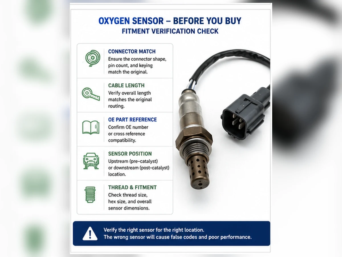
- OE or OEM number: capture the original number when readable, but confirm supersessions and service-part updates.
- Year, make, model, and engine: include displacement, engine code, fuel type, and VIN breakpoint when the catalog requires them.
- Market and emission configuration: Federal, California/CARB, export-market, and engine-family differences can affect sensor selection.
- Exact position: upstream/downstream, Bank 1/Bank 2, Sensor 1/Sensor 2, and converter branch.
- Sensor technology: zirconia narrowband, titania, wideband/AFR, heated/unheated, and manufacturer-specific control requirements.
- Connector and harness: pin count, keying, latch, cable length, heat shielding, strain relief, clips, and routing.
- Mechanical details: thread, hex size, protective shield, body clearance, and sealing arrangement.
- Replacement format: direct-fit versus universal, including approved splice method and local compliance requirements.
- Supplier evidence: catalog source, cross-reference basis, warranty terms, traceability, packaging, and return policy.
OE number versus cross-reference
An OE number is a strong identity input, but it can be superseded or vary by region and emission package. An aftermarket cross-reference is a candidate match generated by a catalog or supplier; it is not proof of interchangeability unless the underlying application data, technology, connector, dimensions, and position agree.
Why wire count is not enough
Two sensors with four or five wires may use different signal strategies, heater resistance, calibration, connector keying, or reference circuits. Matching wire colors visually is also unreliable across manufacturers. Use a validated application catalog and technical data, not a wire-count shortcut.
Questions for a supplier
- Which OE number and vehicle configuration supports this cross-reference?
- Is the part direct-fit for the exact bank and sensor position?
- What sensor technology and heater specification does it use?
- Are connector keying, cable length, clips, and heat protection application-specific?
- How is lot traceability handled, and what is the warranty or return process for a catalog mismatch?
- Is the product legal for the intended market and emissions configuration?
Evaluate the supplier’s fitment evidence
| Evidence level | Example | Purchasing interpretation |
|---|---|---|
| Strong | OE catalog reference plus YMME, engine, emission configuration, exact position and technical specification | Suitable basis for a fitment review, subject to current supersession and market checks |
| Moderate | Established aftermarket catalog with position, connector and technology data | Useful candidate cross-reference; verify against the vehicle and original part |
| Weak | Part photo, thread size, wire count or a broad list of vehicle names | Insufficient to establish electrical and functional compatibility |
| Unacceptable | “Universal direct fit,” no catalog source, or a seller unwilling to identify the position and technology | High mismatch risk; do not treat as verified fitment |
For distributor or sourcing programs, fitment accuracy should also be connected to revision control, lot traceability, packaging identification, mismatch handling and a documented return or warranty process. These are procurement controls, not evidence that a particular Sunhyings oxygen-sensor program currently exists.
Direct-fit vs universal oxygen sensors
A direct-fit sensor includes an application-specific connector and harness arrangement. A universal sensor requires an approved connection method and still must match the sensing technology, heater characteristics, dimensions and intended application. Universal does not mean compatible with every vehicle.
| Factor | Direct-fit | Universal |
|---|---|---|
| Connector | Application-specific connector supplied | Existing connector may need to be retained |
| Installation | Normally plug-in after mechanical installation | Requires the manufacturer-approved wire connection |
| Cable length and routing | Cataloged for the application | Must be checked carefully |
| Wiring risk | Lower when catalog fitment is correct | Higher if wire identification or sealing is wrong |
| Technology match | Still must be verified | Must be verified before splicing |
Minimum acceptance criteria for a universal sensor
- The sensor manufacturer explicitly supports the application or equivalent technical system.
- The sensing technology and heater/control requirements match the vehicle.
- The approved connection method preserves sealing, strain relief and any reference-air requirement.
- The finished cable length and routing keep the harness away from exhaust heat and moving parts.
- Local emissions and inspection rules permit the intended repair.
If any of these conditions cannot be verified, a validated direct-fit sensor is the lower-risk purchasing path.
Prevent repeat failure and avoid non-compliant fixes
Replacing a sensor from one code
Codes identify a monitored fault area. They do not eliminate wiring, leaks, fuel-control, ignition, controller, or catalyst causes.
| Condition | Possible effect on the sensor or signal | Required action |
|---|---|---|
| Oil consumption | Deposits or contamination on the sensing element and catalyst | Diagnose the oil-consumption source before expecting normal service life |
| Coolant entry | Contamination and abnormal exhaust chemistry | Repair the engine or cooling-system fault |
| Rich operation or leaking injector | Thermal stress, deposits and catalyst overheating | Correct fuel control and verify trims |
| Repeated misfire | Unburned oxygen and fuel distort readings and heat the catalyst | Repair ignition, fuel or mechanical causes |
| Exhaust leak | Additional oxygen can create a false lean indication | Repair the leak and retest the system |
| Harness heat or water damage | Intermittent signal, heater or reference-circuit faults | Restore routing, sealing and circuit integrity |
Confusing bank and position
“Left,” “right,” “front,” and “rear” can be ambiguous. Use cylinder numbering and exhaust layout.
Buying by connector appearance
Similar plugs do not prove matching sensor technology, heater load, calibration, or cable length.
Ignoring the root cause
Oil burning, coolant entry, silicone contamination, rich operation, misfire, or exhaust leaks can damage a new sensor or repeat the code.
Applying a generic torque
Thread size, coating, bung material, and manufacturer procedure matter. Use the specified installation torque.
Using a spacer, simulator, delete, or bypass
These do not repair the underlying fault and may constitute illegal emissions tampering. Restore the system through compliant diagnosis and repair.
Final pre-purchase checklist
- The fault has been diagnosed rather than inferred from one symptom or code.
- Stored, pending and permanent codes plus freeze-frame data have been recorded.
- The exact bank, sensor number and upstream/downstream position are known.
- Intake leaks, exhaust leaks, misfire, fuel-control faults and wiring faults have been considered.
- The OE number or a validated, current cross-reference is available.
- Year, make, model, engine, VIN breakpoint, market and emissions configuration are confirmed where required.
- Sensor technology, connector keying, pin arrangement, cable length and routing provisions match.
- Thread, hex, shield, sealing arrangement and body clearance match the installation.
- The contamination or repeat-failure mechanism has been corrected before installation.
- The supplier can document the fitment basis, part identification, warranty and return process.
Prepare this data before requesting a fitment or sourcing review
Send a complete fitment identity rather than “I need an O2 sensor for a 2018 car.” At minimum, include:
Use the structured data table below as the minimum request package. Add clear photos of the installed sensor, connector, wire routing, part markings and installation position when catalog data alone cannot resolve the application.
Evidence boundary: Sunhyings does not currently use this educational page as evidence of a published oxygen-sensor product range, confirmed OE cross-reference, vehicle fitment, inventory, or manufacturing capability. Any sourcing inquiry requires separate technical and commercial confirmation.
Submit fitment data for capability review| Data group | Minimum input |
|---|---|
| Vehicle identity | Year, make, model, engine, VIN breakpoint when applicable, market and emissions configuration |
| Part identity | OE number, current installed-part marking, validated cross-reference and exact bank/sensor position |
| Physical and electrical identity | Sensor technology, connector photos, pin count, cable length, thread, hex, shield and routing features |
| Diagnostic context | Codes, freeze frame, completed circuit/leak checks and reason replacement is requested |
| Commercial and quality inputs | Quantity, packaging, labeling, traceability, inspection, warranty and approval expectations |
Frequently asked questions
Can you drive with a bad oxygen sensor?
A vehicle may still run, but continued driving can increase fuel consumption and emissions and may contribute to catalyst damage when the engine is running excessively rich. A flashing malfunction indicator lamp, severe misfire, loss of power, overheating catalyst, or unsafe drivability requires prompt professional attention. Diagnose the system rather than assuming the sensor is the only fault.
Does a P0420 or P0430 code mean the oxygen sensor is bad?
No. These codes concern catalyst-system efficiency monitoring. A sensor, wiring problem, exhaust leak, engine-control issue, or catalyst fault can affect the result, but the code alone does not prove which part failed. Review freeze-frame data, other codes, fuel control, exhaust integrity, and manufacturer service information.
What does Bank 1 Sensor 1 mean?
Bank 1 is the cylinder bank that contains cylinder number 1. Sensor 1 is generally the sensor before the catalytic converter for that bank. Engine layout varies, so do not identify Bank 1 only by the driver or passenger side; verify the engine-specific service information.
Should all oxygen sensors be replaced at the same time?
Not automatically. Replace the sensor or circuit that has been properly diagnosed, unless the vehicle manufacturer specifies a paired replacement or the remaining sensors have a documented condition that justifies replacement. Replacing several sensors without testing can add cost without fixing the root cause.
Is a direct-fit oxygen sensor better than a universal sensor?
For most routine repairs, a verified direct-fit sensor reduces connector, wire-routing, and splice risks. A universal sensor can be appropriate only when its sensing technology, heater characteristics, wiring method, dimensions, and application instructions match the vehicle. Wire count alone is not enough to establish compatibility.
Can an oxygen sensor be cleaned instead of replaced?
Cleaning is not a reliable repair for an electrically failed, slow, contaminated, or damaged sensing element. Solvents and mechanical cleaning can damage the sensor. Diagnose and correct the source of contamination, then follow the vehicle and sensor manufacturer’s repair instructions.
How long does an oxygen sensor last?
There is no universal replacement interval for every vehicle. Sensor design, operating temperature, oil or coolant contamination, rich operation, wiring condition, and the manufacturer’s maintenance strategy all affect service life. Follow the owner or service manual and replace a sensor when testing confirms the need.
Technical references and cost sources
- Bosch Aftermarket — Lambda Sensors: Technology, Diagnosis and Replacement. Used for step-change versus broad-band principles, upstream/downstream roles and diagnosis-before-replacement checks.
- DENSO — O2 and A/F Sensor Troubleshooting. Used for Bank 1 identification by cylinder number 1 and Bank/Sensor location terminology.
- NTK / Niterra — Oxygen / Lambda Sensors. Used for zirconia, titanium-dioxide and broad/wideband/linear sensor-family distinctions.
- Walker Products — Oxygen Sensor Training Guide. Supplemental source for direct-fit/universal distinctions and the boundary between a diagnostic code and confirmed sensor failure.
- U.S. EPA — Transportation, Air Pollution and Climate Change FAQs. Used for the U.S. emissions-tampering context.
- U.S. EPA — Aftermarket Defeat Devices and Tampering Enforcement Alert. Used for defeat-device and onboard-diagnostic monitoring compliance boundaries.
- RepairPal — Oxygen Sensor Replacement Cost Estimate. Used for the U.S. professional average of $454–$551 checked July 22, 2026.
- AutoZone — Oxygen Sensor Replacement Cost. Used for the DIY sensor range of approximately $20–$300 checked July 22, 2026.
- Cars.com — When Should the Oxygen Sensor Be Replaced?. Supplemental consumer source supporting the absence of one universal replacement interval.
Technical sources and time-sensitive U.S. cost estimates were checked on July 22, 2026; the final page artifact was reviewed on July 23, 2026. Always prioritize the vehicle manufacturer’s current service information, wiring diagrams, part catalog, technical service bulletins and market-specific emissions requirements.