








Oxygen Sensor Technical Guide
A Ford oxygen sensor replacement guide focused on diagnosis, exact vehicle and engine identity, sensor position, fitment evidence and safe verification.
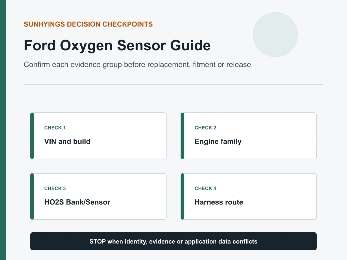
Quick answer
For a Ford vehicle, do not select or replace an oxygen sensor by model name or trouble code alone. Confirm the exact year, model, engine, VIN/build data, sales market and emissions configuration; then identify Bank and Sensor position, sensor technology, OE reference, connector and lead. Ford code descriptions commonly use HO2S and Bank/Sensor designations, but engine and exhaust layouts vary widely. A code narrows the test path but does not prove the sensor failed.
What this Ford guide can and cannot confirm
This is a neutral diagnostic and fitment-verification guide. It does not publish an unverified Ford OE number, model-year application, sensor count, labor time or torque value. Sunhyings inventory, manufacture and approved fitment are not claimed. Exact service information and current application data for the VIN/configuration control the repair.
Popular Ford model names are not complete fitment identities
| Model search | Information still required | Why it matters |
|---|---|---|
| F-150 oxygen sensor | Year, engine, VIN/build, market/emissions and exact position | One model name can cover different exhaust and sensor systems. |
| Mustang oxygen sensor | Year, engine, VIN/build, market/emissions and exact position | One model name can cover different exhaust and sensor systems. |
| Explorer oxygen sensor | Year, engine, VIN/build, market/emissions and exact position | One model name can cover different exhaust and sensor systems. |
| Escape oxygen sensor | Year, engine, VIN/build, market/emissions and exact position | One model name can cover different exhaust and sensor systems. |
Build the vehicle and sensor identity
- VIN and exact year/model/trim context
- Engine displacement/code and fuel type where applicable
- Sales market and emissions label/configuration
- Bank 1 or Bank 2 and Sensor 1 or Sensor 2
- OE number from a verified source or readable old-part label
- Sensor technology, connector keying, pins, lead and clips
Diagnose before ordering
Record current, pending and permanent codes, freeze frame and readiness. Inspect harness routing, terminals and exhaust leaks. Test heater power/ground/control for heater codes. Compare fuel trims and technology-specific sensor response for mixture or response codes. P0420/P0430 concerns catalyst-system efficiency and is not an automatic rear-sensor order.
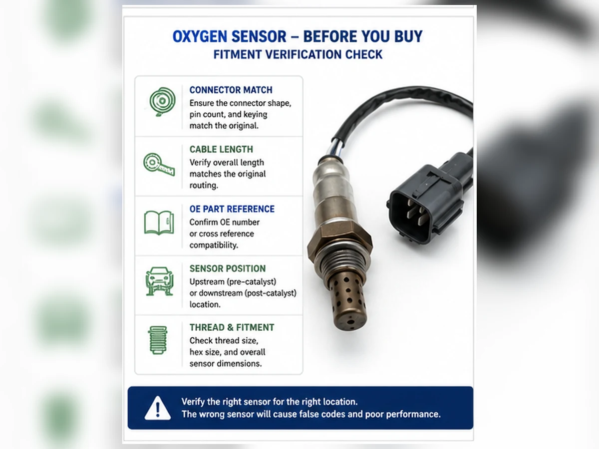
Safe installation boundary
Let the exhaust cool and use approved vehicle support. Follow the exact Ford service procedure and replacement-sensor instructions for access, torque and thread compound. Do not cut a direct-fit harness. Route the lead away from heat, sharp edges and moving parts, and restore every clip and shield.
Post-repair verification
Check the connector, routing and exhaust sealing, then confirm heater/circuit and sensor response under specified conditions. Complete the applicable legal monitor procedure. Clearing codes, using a spacer/simulator or disabling a monitor does not prove repair.
A Ford verification sequence that avoids model-name guessing
| Step | Evidence to record | Stop condition |
|---|---|---|
| Vehicle identity | VIN, year, model, engine/build and sales market | Engine or configuration remains ambiguous |
| Emissions identity | Under-hood label and applicable regional configuration | Catalog does not distinguish the configuration |
| Physical position | Bank, Sensor number and catalyst relationship | Service and physical diagrams do not agree |
| Part identity | OE reference, technology, connector, lead and clips | Any critical field conflicts |
| Failure evidence | Codes, circuit checks, leaks, trims and response test | Sensor failure is not supported |
Ford model lines, especially F-150, can offer several engines in the same year. Engine family, aspiration, build data and emissions market are required. NHTSA VIN decoding can assist vehicle identity but does not provide a complete Ford service procedure or prove sensor fitment.
Questions to answer for common Ford model searches
| Search phrase | Questions before diagnosis or ordering |
|---|---|
| F-150 oxygen sensor | Which model year, engine family, turbo/non-turbo configuration, emissions market, bank and HO2S position? |
| Mustang oxygen sensor | Which engine and generation? Where is cylinder 1, and which catalyst path does the code identify? |
| Explorer oxygen sensor | Which engine, drivetrain/build configuration and Bank/Sensor position? Are connector routes confirmed from exact wiring data? |
| Escape oxygen sensor | Which gasoline, turbo or hybrid powertrain and market? What technology and OE reference applies to the exact position? |
A model-family table is a verification checklist, not a fitment list. It intentionally contains no sensor count, side, OE number or year range. Those facts must come from current information matching the exact vehicle.
Read Ford terminology in context
Oxygen sensor, heated oxygen sensor and A/F sensor
Ford diagnostic descriptions commonly use HO2S plus Bank/Sensor designations; the displayed term still must be matched to exact engine and circuit data. “Oxygen sensor” and “O2 sensor” name the broad family. A/F, wideband and heated labels can imply different circuits or roles, but the complete service description controls. Do not infer technology from the number of wires or from a marketplace title.
Bank and Sensor designation
Bank 1 contains cylinder 1. Sensor 1 is commonly before the relevant catalyst and Sensor 2 after it. This common naming helps orient the reader but does not provide a universal physical side. Confirm cylinder numbering and exhaust flow for the exact engine.
Generic scan-tool labels
A scan tool may display HO2S voltage, A/F current, lambda or equivalence ratio. Confirm that the PID is supported, matches the physical circuit and uses the expected units. A generic menu can list positions or values that are not implemented for the vehicle.
Map engine banks, catalysts and connectors
F-150, Mustang and Explorer engine choices can include one- or two-bank reasoning and different catalyst paths, while Escape configurations can introduce different powertrains. Never infer Bank 1 from driver/passenger side or sensor count from the model name.
| Map item | Evidence source | Common error prevented |
|---|---|---|
| Cylinder 1 and bank | Exact engine service diagram | Driver/passenger or front/rear shortcut |
| Catalyst order | Exhaust layout for the configuration | Wrong Sensor 1/Sensor 2 position |
| Connector route | Wiring diagram and cool physical inspection | Testing a nearby but different circuit |
| Sensor technology | Service and approved application data | Narrowband/wideband test mismatch |
Account for engine, build and emissions variants
An F-150 engine option is a critical fitment field, not a trim detail. Mustang and Explorer generations also change engines and exhaust packaging. Escape gasoline, turbo and hybrid contexts must remain separate. Use build/VIN and emissions evidence with the exact engine.
A registration year or model badge does not necessarily equal production date or VIN breakpoint. Imported vehicles can also differ from the market assumed by a local catalog. Record the under-hood emissions label and use a catalog that explicitly covers the sales market.
Turn Ford codes into test paths, not part orders
| Code type | First checks | Do not conclude |
|---|---|---|
| Heater circuit | Correct position, fuse/supply, ground/control, connector and element | The sensor is failed from code alone |
| Low/high/no activity | Signal/reference circuit, operating state and real mixture | A displayed limit identifies the failed component |
| Slow response | Enable criteria, leaks, technology and controlled response | Every slow graph requires replacement |
| P0420/P0430 | Misfire, fuel control, leaks, both sensors and catalyst | The downstream sensor is automatically bad |
Save all current, pending and permanent codes, freeze frame and readiness before clearing. Multiple codes can reveal a shared supply, system-wide mixture fault or misfire. Clearing memory can remove context and reset monitors without repairing anything.
Interpret live data with technology and operating state
Confirm warm-up and control state
A cold sensor or engine outside closed-loop conditions should not be compared with a warm response specification. Record coolant temperature, load, speed and commanded state with the sensor value.
Compare response with fuel trims
Positive or negative correction shows what the control module is attempting, not which component failed. Intake leaks, airflow/load error, fuel delivery, purge, ignition and mechanical condition can create the exhaust result a healthy sensor reports.
Use downstream data in catalyst context
The downstream signal is evaluated with upstream behavior and catalyst monitor conditions. A waveform comparison without exhaust sealing, engine condition and valid monitor criteria cannot establish a failed sensor or catalyst.
Build the replacement identity only after diagnosis
| Fitment field | Required evidence | Reject when |
|---|---|---|
| OE reference | Readable part or current controlled catalog source | Unverified cross-reference or unresolved supersession |
| Vehicle scope | VIN/build, engine, market and emissions configuration | Model/year only |
| Position | Bank/Sensor and catalyst relationship | “Front” or “rear” remains ambiguous |
| Technology | Specified narrowband, wideband/A/F or other circuit | Wire count is the only match |
| Interface | Thread, shield, connector, pins, lead and clips | Harness must be forced, cut or stretched |
For Ford, include the complete engine/build identity and full DTC wording, not just HO2S. Match the OE candidate, bank, sensor number, catalyst relationship, connector pinning and lead route. Do not transfer a part across F-150 engine options or Ford model lines without approved coverage.
Direct-fit and universal are separate decisions
A direct-fit sensor supplies an application connector and lead arrangement, but it still needs exact coverage. A universal sensor requires manufacturer-approved circuit compatibility and splice instructions; universal does not mean every Ford vehicle. Wire colors are not a universal pinout standard. Do not cut a direct-fit harness or improvise a splice near the exhaust.
Installation and safety checks
- Let the exhaust cool and use approved vehicle lifting/support.
- Confirm the physical sensor and connector before disconnection.
- Protect exhaust threads and nearby components during removal.
- Compare old and replacement technology and interface details.
- Follow exact product/service torque and thread-compound instructions.
- Restore heat sleeves, clips, shields and safe cable routing.
There is no responsible universal torque or labor time for every Ford application. Access, corrosion, sensor design and surrounding components vary. Stop when threads, bung, connector or harness damage changes the job scope.
Use an evidence hierarchy when sources disagree
Search results often combine owner discussions, marketplace listings, generic code definitions and application catalogs. They do not have equal authority. Start with exact Ford service information for circuit identity, diagnostic conditions, connector views and installation procedure. Use a current controlled parts source for OE identity and supersession. Use the under-hood label, VIN/build data and the removed part to resolve configuration. Aftermarket catalogs can then be evaluated as cross-references, not treated as proof merely because several sellers repeat the same row.
| Evidence source | Appropriate use | Boundary |
|---|---|---|
| Exact service information | Position, circuit, test conditions and repair procedure | Must match engine, market and configuration |
| Controlled OE parts data | Part identity, position and supersession path | A supersession still needs application reconciliation |
| VIN/build and emissions label | Vehicle and regulatory configuration | VIN decoding alone does not provide the repair test |
| Removed sensor and connector | Physical comparison and readable identifiers | Appearance cannot prove electrical compatibility |
| Aftermarket catalog | Candidate cross-reference and commercial coverage | Source, revision and exclusions must be known |
| Forum or marketplace page | Possible symptom or terminology lead | Not approval evidence for diagnosis or fitment |
When two controlled sources conflict, record both values, their dates and the exact vehicle fields used. Do not average the answers or choose the listing with the clearest product photo. Hold the affected application until the conflict is resolved by an authoritative source or a documented physical and electrical comparison.
Build a diagnostic evidence packet before replacement
A useful record lets another technician understand why replacement was approved. Capture the full DTC description and status, freeze-frame conditions, relevant service-test step, battery/system voltage, heater power and control checks where applicable, harness and terminal condition, intake and exhaust leak findings, fuel trims, misfire evidence and the technology-specific sensor response. Identify the physical connector tested. A graph without vehicle state, units and sensor position cannot be interpreted reliably.
Separate observations from conclusions. “P0135 stored” is an observation. “The heater has specified supply but an open element at the identified connector” is evidence supporting a sensor decision. “The sensor is bad” based only on a code is an unsupported conclusion. The same discipline applies to mixture and catalyst-monitor codes: document the competing causes that were tested and the condition under which the monitor or response failed.
Preserve evidence after the repair
Record the installed part identity and lot if available, connector engagement, cable route, exhaust sealing and post-repair values under comparable conditions. Do not erase the before-state before it is saved. If a concern returns, this packet separates wrong fitment, installation damage, circuit recurrence, unresolved engine faults and possible product nonconformity. It also gives a supplier enough information to investigate without assuming every warning light is a warranty defect.
Compare the old and replacement sensor as a system
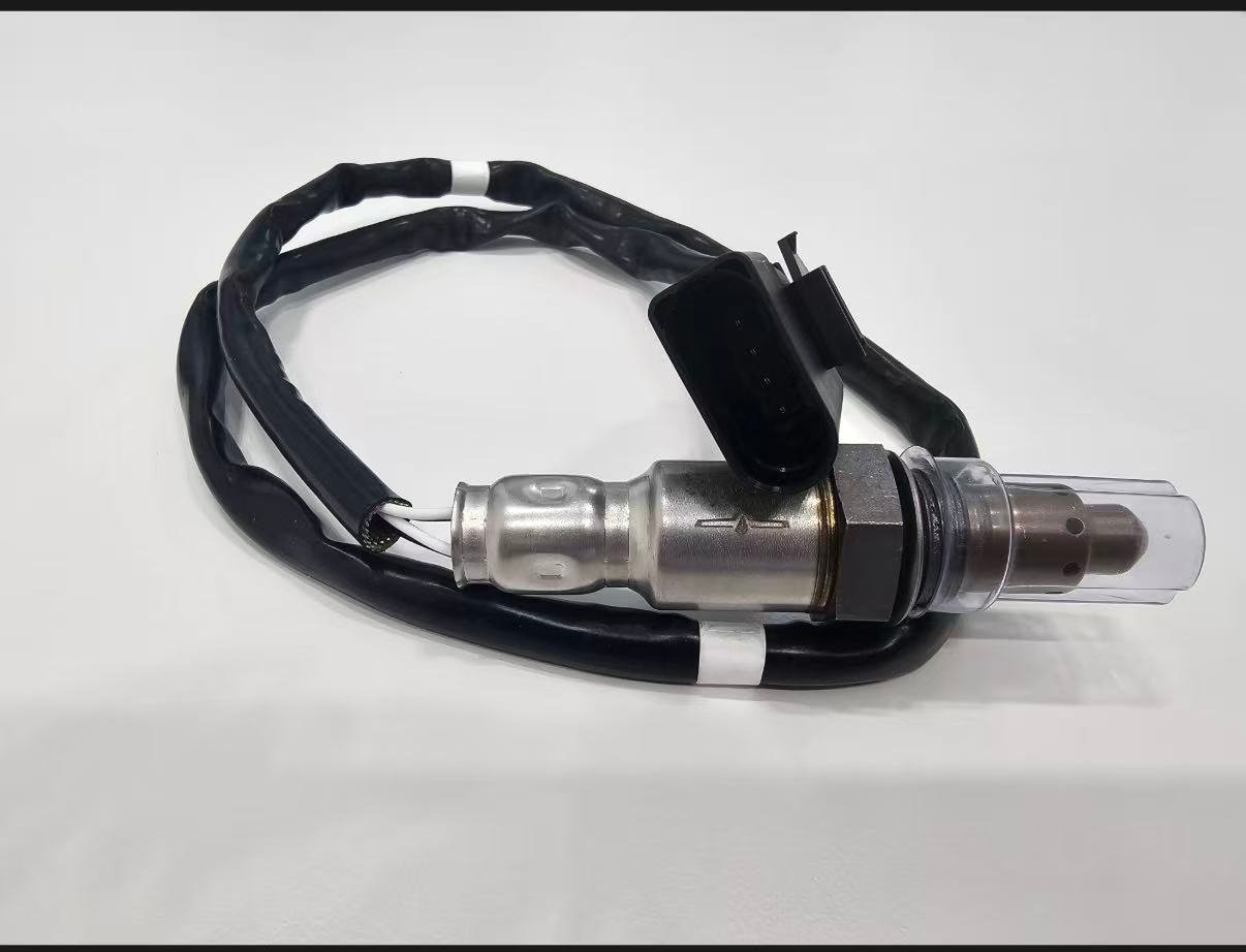
Place the parts side by side without contaminating or striking the sensing element. Compare the stamped or labeled identifiers, thread and sealing seat, hex access, shield length and hole pattern, cable protection, overall lead length, grommets and clips, connector housing, keying, latch, terminal count and secondary lock. Then compare the drawing or application specification. A visible match is a rejection screen, not final approval: heater resistance range, signal strategy, calibration and pin assignment may differ while housings look alike.
Reject or stop the installation if the cable must be stretched across the exhaust, the connector needs force, a clip cannot return to its original location, the shield contacts another component, the thread or seat differs, or the specified technology cannot be confirmed. Do not modify a direct-fit connector to make a candidate fit. If a universal sensor is expressly approved, use only its manufacturer’s application and splice procedure and retain the harness protection required near the exhaust.
Use explicit stop, diagnose and release decisions
A good workflow does not force every inquiry toward a sale. Use three visible states. Stop when vehicle identity, emissions configuration, physical position or sensor technology is ambiguous, or when two authoritative sources conflict. Diagnose when fitment is known but the evidence does not establish sensor failure; complete the circuit, leak, fuel-control and response checks required by the complaint. Release only when both the replacement need and the part identity are supported. Record who made the decision and which evidence was used.
This separation prevents a correct diagnostic conclusion from being paired with the wrong part, and it prevents a correct-looking part from being sold for an undiagnosed fault. It also gives customer service a truthful response when key data is absent: the status is Pending, not “probably fits.” For an RFQ, quote only released application rows and list blocked rows separately. For a repair, keep the original evidence until the relevant circuit response and legal monitor are verified after installation.
| Decision state | Typical evidence | Permitted next action |
|---|---|---|
| Stop | Engine, market, position, technology or source conflict | Request authoritative data; do not order or claim fitment |
| Diagnose | Vehicle/circuit known, failure cause still open | Run the exact service test and competing-cause checks |
| Release | Failure evidence and complete replacement identity agree | Approve the controlled part/application and installation plan |
| Verify | Installed identity, routing, sealing and response documented | Confirm repair under specified conditions and monitor status |
Read the complete Ford HO2S description
Ford diagnostic language commonly uses HO2S together with Bank and Sensor identifiers. Keep the complete wording. “HO2S11” or a description naming Bank 1 Sensor 1 contains position information that is lost when it becomes “front O2 sensor.” The full code status, freeze frame and circuit description should travel together from diagnosis to the parts request. A code-family label may identify signal, heater or response behavior, but it does not establish which physical component caused the condition.
Ford powertrain data can be manufacturer-specific, while a generic scan tool may simplify labels or show unsupported PIDs. Confirm the chosen data item against exact service information and identify its units. A voltage, current, lambda or equivalence-ratio value must be interpreted using the correct sensor strategy and operating conditions. Do not judge a wide-range upstream device by a generic narrowband switching rule, and do not compare two banks until engine load, temperature and test conditions are comparable.
| Ford record | Keep intact | What can go wrong if shortened |
|---|---|---|
| DTC | Number, full description, status and freeze frame | Signal and heater paths are confused |
| HO2S identity | Bank, Sensor and catalyst relationship | Wrong physical connector is tested |
| Powertrain | Engine family, aspiration/hybrid context and build | F-150 or Escape variants are merged |
| Data item | PID name, units, state and sampling conditions | Generic graph is misinterpreted |
Engine option is a primary Ford fitment key
F-150 is the clearest example: one model year can contain several engine families and exhaust layouts. Mustang and Explorer also change engine and catalyst packaging across generations, while Escape can add turbocharged or hybrid powertrains. Record the exact engine from authoritative build/VIN data before opening the wiring diagram or catalog. Displacement text alone may still be insufficient where engine families or calibrations differ.
Do not infer the number of sensors from the engine’s cylinder count. Count exhaust paths, monitored catalysts and identified positions in the exact service and parts information. A two-bank engine can have multiple catalysts or connector routes that make the nearest visible sensor a poor guide. A single-bank configuration does not gain a second physical bank because a generic scan-tool menu displays Bank 2 choices.
Build a Ford bank and exhaust-path map
- Confirm engine family, build date and emissions market.
- Locate cylinder 1 using the matching Ford engine diagram.
- Trace each manifold or turbo outlet to its catalyst sequence.
- Mark Sensor 1 and Sensor 2 relative to the relevant catalyst.
- Follow the wiring diagram to connector number and harness branch.
- Compare the physical connector, lead route and clips only after the map is complete.
This method matters on vehicles where exhaust components cross, merge or package tightly around the transmission and frame. “Left” or “right” can refer to vehicle orientation, component view or catalog convention; Bank 1 remains the bank containing cylinder 1. Document the diagram reference used so another person can reproduce the location decision.
Ford HO2S diagnostic paths by evidence type
For a heater fault, check the exact circuit’s fused supply or shared supply, control side, terminal tension, corrosion and harness heat damage before measuring the element by the Ford procedure. Several heater codes can indicate a shared electrical problem. For a low, high or no-activity code, confirm reference/signal integrity and whether a genuine rich or lean exhaust condition exists. Fuel trims, airflow/load data, fuel delivery, purge, ignition, mechanical condition and leaks supply that context.
A slow-response code is monitor evidence, not a stopwatch instruction detached from enable criteria. Confirm temperature, load, sensor strategy and exhaust sealing, then use the specified response test. For P0420/P0430, evaluate misfire and mixture history, exhaust leaks, the correct upstream/downstream pair and catalyst evidence. Replacing Sensor 2 merely because its code description mentions a catalyst bank does not repair an efficiency problem.
Harness routing deserves its own decision
Ford truck and SUV packaging can expose long leads and clips to exhaust heat, road contamination or movement. Inspect the entire route, not only the connector end. A melted sleeve, missing clip, stretched branch or terminal fretting can create intermittent faults after warm-up. Restore every protective feature. A new sensor connected through the same damaged route can repeat the code and falsely appear defective.
Ford sourcing and catalog release gate
| Gate | Pass evidence | Block signal |
|---|---|---|
| Build identity | VIN/build and exact engine family | Model/year or displacement only |
| Emissions scope | Market/configuration explicitly covered | Catalog silently assumes one region |
| HO2S position | Bank/Sensor mapped to catalyst and connector | Driver/passenger shortcut |
| OE/cross-reference | Current source, revision and supersession resolved | Marketplace repetition is the only source |
| Technology/circuit | Electrical strategy and pin assignment confirmed | Connector shell or wire count only |
| Physical route | Lead, clips, shield and heat clearance verified | Cable must be stretched or rerouted |
For wholesale coverage, release applications by engine and position, not by a headline such as “fits F-150.” Keep excluded engines and unresolved build ranges visible in the application file. Sunhyings can review a Ford project when these fields are supplied, but product availability, OE equivalence and fitment require project-specific evidence before quotation.
Composite Ford verification scenario
Composite engineering scenario: an F-150 request lists only model year and a P-code. Several engines were available, and the buyer assumes the visible sensor on the driver side is the named Bank 1 circuit. The reviewer pauses the order, resolves vehicle and position identity, and then follows the correct circuit test. This scenario combines common catalog and diagnostic risks; it is not a Sunhyings customer case, fitment record or claim about a particular vehicle.
Composite Ford diagnostic scenario
Composite diagnostic scenario: An Explorer stores a slow-response code and the first scan graph appears flat. The technician does not order an HO2S from the graph alone. Exact build and engine data identify the circuit and signal type; the test is repeated after warm-up while fuel trims and commanded conditions are recorded. A heat-damaged harness section responds to movement, so circuit routing is repaired and verified before any sensor replacement decision.
The sequence is intentionally evidence-led: confirm the exact circuit, test the vehicle-side causes and compare the response with the applicable procedure before approving a part. It is a composite training example, not a Sunhyings customer, warranty result or statement that the named model commonly has this fault.
Verify the repair and monitor
After repair, confirm connector lock, lead routing, heat clearance and exhaust sealing. Check the heater/circuit and technology-specific sensor response under defined conditions. Complete the applicable legal readiness monitor. A warning light that was cleared manually is not evidence that the original monitor passed; permanent codes may remain until the control module confirms a successful result.
Emissions and product-claim boundary
Do not use spacers, defoulers, simulators, sensor deletes or software changes to conceal catalyst monitoring. These methods do not repair the root cause and may violate emissions law. This educational page does not confirm that Sunhyings sells, stocks, manufactures or guarantees a sensor for any Ford application. Fitment remains Pending until project-specific evidence is matched.
Prepare a fitment or sourcing request
Send the OE number, year/make/model, engine or VIN details, market and emissions package, exact bank/sensor position, connector and old-part photos, quantity and any packaging or approval requirements. Sunhyings will review the supplied data for capability and sourcing feasibility; fitment is not confirmed until application evidence is matched.
Frequently asked questions
How do I find the correct Ford oxygen sensor?
Use the VIN/configuration, engine, market/emissions package, exact bank and position, OE reference, technology and connector/cable details.
Does a Ford oxygen-sensor code prove the sensor failed?
No. Diagnose wiring, heater supply/control, exhaust leaks, fuel trims and sensor response using exact service information.
Is Bank 1 always on one side of a Ford?
No. Bank 1 contains cylinder 1; its physical side depends on the engine and installation.
Can Sensor 1 and Sensor 2 use the same part?
Only when current verified application data lists that exact part for both positions.
Does P0420 mean replace the downstream sensor?
No. P0420 is a catalyst-system efficiency code and requires engine, exhaust, sensor and catalyst diagnosis.
Can Sunhyings confirm Ford fitment from a model name?
No. Submit complete vehicle, engine, emissions, position and OE/physical evidence for a fitment review.