Projection Weld Nuts for Automotive Sheet Metal: Torque-Out, Pull-Out and Projection Design
Projection weld nuts for automotive sheet metal are not selected by thread size alone. A weld nut may look simple, but its final performance depends on nut geometry, projection design, sheet metal thickness, material condition, surface condition, welding process, fixture control and inspection requirements.
This guide helps buyers confirm torque-out, pull-out, projection design, sheet metal condition, welding compatibility and RFQ data before sampling or production approval. Use it to reduce unclear RFQs, avoid wrong weld nut assumptions, and separate nut manufacturability from final welding validation responsibility.
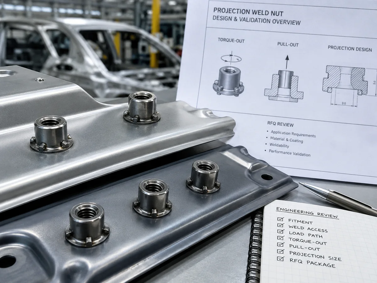
Projection weld nuts for automotive sheet metal should be reviewed by thread requirement, projection design, sheet condition, torque-out, pull-out and inspection scope.
Conceptual engineering visual only; final weld performance depends on buyer sheet metal, welding process and customer validation.
Quick Answer: What Should Buyers Confirm First?
Before sourcing projection weld nuts for automotive sheet metal, buyers should confirm the nut drawing, thread requirement, projection design, sheet metal thickness, sheet material, surface condition, welding route, torque-out requirement, pull-out requirement and inspection responsibility.
A projection weld nut is not approved only because the thread size matches the bolt. The nut must also form a stable welded joint with the sheet metal after projection welding. Torque-out and pull-out requirements cannot be assumed from nut size alone.
First Check
Why It Matters
Buyer Action
Thread size, pitch and tolerance
Controls mating bolt fit after welding
Provide drawing thread callout and gauge requirement
Nut type
Flange, hex and custom weld nuts may use different geometry
Confirm exact nut drawing or standard
Projection geometry
Controls weld current concentration and projection collapse
Follow drawing or approved design
Sheet metal thickness
Affects weld formation, pull-out behavior and burn-through risk
Provide sheet thickness and tolerance
Surface condition before welding
Coating, plating, oil or pretreatment may affect welding stability
Confirm bare, galvanized, coated or pre-treated sheet
Torque-out and pull-out
Defines rotational and axial retention requirements
Provide test method and acceptance value if required
Approval documents
Automotive projects may require reports, PPAP or control plan
Confirm only if required by customer or program
No Universal Test Value
No universal torque-out or pull-out value should be written into the RFQ unless it comes from the drawing, customer standard or approved test specification. Missing information should be marked as needs confirmation.
What Are Projection Weld Nuts for Automotive Sheet Metal?
Projection weld nuts are nuts designed with raised projections that concentrate welding current, heat and pressure during resistance projection welding. When the welding process is correctly controlled, the projections collapse and help form a welded joint between the nut and the sheet metal.
In automotive sheet metal assemblies, projection weld nuts are often used where a reliable threaded attachment point is required on a thin or formed metal part. They may be used on brackets, reinforcements, panels, mounting points or other sheet metal components. The exact application location, joint type and load condition must be confirmed from the drawing or customer specification.
Projection weld nut performance starts with the correct relationship between internal thread, projection geometry, bearing surface and sheet metal contact.
Diagram is explanatory only; projection geometry must follow the approved drawing or customer standard.
Common forms include flange weld nuts, hex weld nuts and custom projection weld nuts. A flange weld nut may provide a larger bearing surface and multiple projections around the flange. A hex weld nut may follow a catalogue or drawing-controlled geometry. A custom projection weld nut may use special projection layout, flange shape, thread requirement or packaging orientation.
For buyers sourcing custom special nuts, the key point is that a weld nut should not be treated as a generic threaded part. A nut that works on one sheet metal application may not be suitable for another if the sheet material, thickness, coating, welding access, electrode, fixture or torque-out requirement changes.
Why Torque-Out and Pull-Out Matter
Torque-out and pull-out are two of the most important validation points for projection weld nuts in automotive sheet metal. They are related to the welded joint, not only to the nut thread.
Torque-out refers to the welded nut’s resistance to rotational failure when torque is applied after welding. If torque-out strength is not sufficient, the nut may rotate in the sheet metal during assembly, service or repair.
Pull-out refers to the welded nut’s resistance to being pulled out of the sheet metal. If pull-out strength is not sufficient, the sheet metal may deform, tear or separate from the welded nut under axial load.
Torque-out checks rotational resistance after welding, while pull-out checks axial retention between the weld nut and sheet metal.
No test value is implied; acceptance criteria must come from the drawing, customer standard or approved test specification.
Torque-out is not the same as assembly tightening torque
Buyers should not confuse torque-out with normal bolt tightening torque. Assembly torque is the torque used when fastening the mating bolt. Torque-out is a validation check for whether the welded nut resists rotating relative to the sheet metal. The relationship between these two values must be defined by the customer drawing, joint design or validation requirement.
Requirement
What It Checks
Why Buyers Should Not Assume It
Torque-out
Resistance to nut rotation after welding
Nut size alone does not define weld strength
Pull-out
Resistance to axial separation from sheet metal
Sheet thickness and weld quality strongly affect results
Thread gauge after welding
Internal thread usability after welding
Welding heat, distortion or spatter may affect thread fit
Position tolerance
Nut location after welding
Fixture and sheet part control affect final assembly
Visual weld condition
Basic weld appearance and projection collapse
Visual review alone does not replace strength validation
Projection Design: What Controls Weld Strength?
Projection design is central to projection weld nut performance. The projections are not decorative features. They control how welding current and pressure are concentrated at the contact points between the nut and sheet metal.
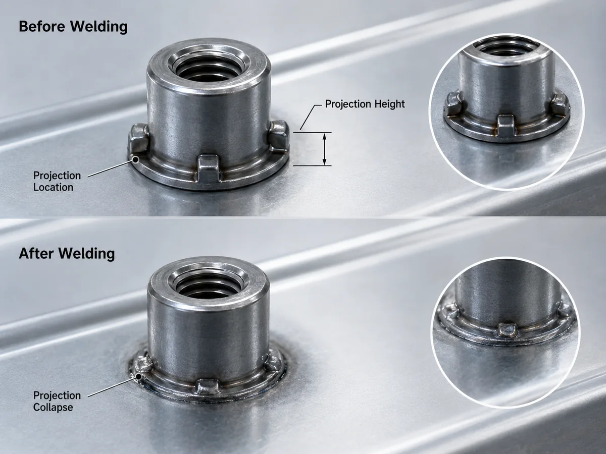
The main projection design variables include number of projections, projection height, projection shape, projection location, projection spacing, projection volume, contact area before welding, projection collapse after welding and compatibility with sheet metal thickness and surface condition.
Projection design controls initial contact, heat concentration and projection collapse, but final weld strength still requires process validation.
Projection geometry should follow the approved drawing; this image does not define final projection dimensions.
Projection Design Item
Why It Matters
Buyer Confirmation
Number of projections
Affects weld point distribution
Confirm drawing requirement
Projection height
Affects initial contact and collapse behavior
Do not assume; follow drawing
Projection shape
Affects current concentration and heat formation
Confirm approved geometry
Projection location
Affects alignment and weld balance
Confirm tolerance and datum
Projection collapse
Indicates welding response during process
Validate through welding trial if required
Contact area
Affects heat and pressure distribution
Confirm sheet and surface condition
Projection Design Is Not a Strength Guarantee
A projection design should not be described as guaranteed strong without welding validation. The nut design, sheet metal and welding process must work together.
Sheet Metal Thickness, Material and Surface Condition
Projection weld nut performance cannot be judged from the nut drawing alone. The mating sheet metal is a critical part of the joint.
Sheet thickness affects weld formation, projection collapse, pull-out behavior and burn-through risk. Sheet material also matters. Different steel grades, strength levels and surface conditions may affect resistance welding stability.
Sheet Metal Input
Why It Matters
Needs Confirmation
Sheet material grade
Affects weldability and deformation behavior
Material grade or customer specification
Sheet thickness
Affects pull-out and burn-through risk
Thickness and tolerance
Surface condition
Affects current flow and weld stability
Bare, galvanized, coated or pre-treated
Welding side access
Affects electrode and fixture design
Access direction and part geometry
Reinforcement plate
Changes effective joint thickness
Single sheet or multi-layer stack
Post-weld coating
Affects corrosion protection plan
Coating, sealing or painting after welding
If the sheet metal data is missing, the supplier can review the nut manufacturability but cannot confirm the final welded assembly performance. The correct status is needs confirmation.
Manufacturing Process Route: What Must Match Between Sample and Production?
For automotive projection weld nut projects, sample approval is only useful when the sample route represents the planned production route. Buyers should confirm whether the quoted nut will be produced, welded, inspected, packed and submitted under the same process assumptions expected for mass production.
Process Route Item
Why It Matters
Buyer / Supplier Confirmation
Nut manufacturing route
Cold forming, machining, tapping or secondary operations may affect cost and repeatability
Confirm drawing-controlled route if specified
Projection forming
Projection shape and consistency affect welding response
Confirm projection geometry follows drawing
Thread forming / tapping
Thread fit after welding must still meet requirement
Confirm thread gauge and inspection condition
Surface condition before welding
Oil, plating or sheet coating may affect welding stability
Confirm welding condition and cleaning requirement if specified
Welding validation route
Final joint strength depends on welding machine, electrode, fixture and schedule
Confirm who owns welding validation
Inspection route
Torque-out, pull-out, sectioning or thread gauge may be required
Confirm test method, sample scope and acceptance criteria
Packaging route
Projection damage, thread contamination or mixed lots can affect production use
Confirm bulk, tray, orientation and label requirements
Production route boundary: SUNHYINGS can review the nut manufacturability and RFQ completeness. Final welding validation depends on the buyer’s sheet metal, welding equipment, electrode condition, fixture, welding schedule and customer acceptance method.
Common Failure Modes in Projection Weld Nut Applications
Projection weld nut failure can come from nut design, sheet condition, welding process, fixture control or inspection gaps. The causes below should be treated as possible causes, not guaranteed conclusions.
A useful RFQ for projection weld nuts should include the full engineering context. Sending only “projection weld nut price” or “automotive weld nut, zinc plated” is not enough.
A projection weld nut RFQ should define the drawing, thread, projection design, sheet metal condition, torque-out, pull-out, inspection scope and document requirements.
Checklist is for RFQ preparation only; PPAP and validation documents apply only when required by the customer or program.
RFQ Item
Why It Matters
Buyer Should Provide
Latest drawing revision
Controls final design baseline
Current drawing and revision
Nut type
Defines product family and geometry
Flange weld nut, hex weld nut or custom weld nut
Thread size, pitch and tolerance
Controls mating bolt fit
Full thread callout
Nut material and hardness
Affects forming, welding and strength review if specified
Material grade, hardness or standard
Projection geometry
Controls welding contact and collapse
Drawing-controlled projection design
Sheet metal material and thickness
Affects weldability and pull-out behavior
Material grade, thickness and tolerance
Surface condition before welding
Affects welding stability
Bare, galvanized, coated or pre-treated
Assembly location and joint type
Defines functional load direction and validation sensitivity
Vehicle area, bracket, panel, reinforcement or mounting location
Torque-out / pull-out requirement
Defines validation requirement
Test method and acceptance value if required
Welding process responsibility
Determines validation ownership
Buyer, supplier or welding integrator
Document scope
Controls quality submission
PPAP, control plan, test report only if required
Annual volume and packaging
Affects tooling, packaging and process route
Prototype, sample and production quantity; packing method
For drawing-controlled projects, buyers can review SUNHYINGS made-to-print special nuts guidance to understand why drawing revision and technical notes must be clear before quotation.
Inspection and Validation: Torque-Out, Pull-Out and Thread Gauge
Inspection for projection weld nuts should cover both the nut and the welded assembly when required. The inspection scope depends on the customer drawing, internal standard and automotive program requirement.
Projection weld nut validation may include welding process review, visual weld condition, torque-out, pull-out and post-weld thread gauge inspection.
Inspection scope depends on the buyer drawing, welding process responsibility and customer approval requirement.
Inspection Item
What It Confirms
Boundary
Torque-out test
Resistance to rotational failure
Acceptance criteria must be provided
Pull-out test
Resistance to axial separation
Test method and sheet condition must be clear
Visual weld review
Basic weld appearance and collapse condition
Does not replace strength test if required
Sectioning / weld nugget review
Weld formation if specified
Only if required by customer or program
Post-weld thread gauge
Thread usability after welding
Gauge condition must be defined
Position tolerance
Nut location after welding
Fixture and sheet control matter
Production control plan
Repeatability during mass production
Required only if customer or program asks
Validation Ownership Must Be Clear
If the nut supplier provides only the projection weld nut, the buyer or welding process owner must still validate the welded assembly under the actual sheet metal, fixture, electrode and welding schedule. Do not move final weld validation responsibility into the nut drawing unless the project scope explicitly requires it.
Drawing Notes That Need Clarification
Many projection weld nut problems begin with unclear drawing notes. The wording may look simple, but it can create different interpretations between buyer, nut supplier, welding supplier and assembly plant.
Unclear Drawing Note
Why It Is Risky
Clarification Needed
“Weld nut”
Does not define projection type or geometry
Exact nut type and drawing
“Projection weld nut”
May still not define projection height, shape or location
Approved projection geometry
“Torque-out required”
No acceptance value or method
Test method and acceptance criteria
“Pull-out required”
No sheet condition or test direction
Sheet thickness, test setup and acceptance criteria
“Suitable for automotive sheet metal”
Too generic
Sheet material, thickness and assembly location
“PPAP required”
Submission scope is unclear
PPAP level, documents and special requirements
What buyers should not write in RFQ
Weak RFQ Wording
Problem
Better Wording
“Send price for M8 weld nut.”
Missing nut type, projection design, sheet and validation data
Send drawing revision, thread callout, projection geometry and application data
“Torque-out must be strong.”
No measurable acceptance requirement
Provide test method and customer-defined acceptance value if required
“Works on galvanized sheet.”
Too broad; surface condition and welding setup are unknown
Confirm sheet material, coating condition and welding responsibility
“Supplier to guarantee weld strength.”
Final weld strength depends on sheet, fixture, electrode and welding schedule
Define whether supplier, buyer or welding integrator owns validation
If a drawing note is unclear, the buyer should not rely on supplier assumption. The requirement should be marked as needs confirmation before quotation or sample production.
Projection Weld Nuts vs Self-Clinching Nuts: When Welding Is Not the Same as Press-In
Projection weld nuts and self-clinching nuts are both used to create threaded attachment points in sheet metal, but they are not the same joining method.
Welding route, sheet condition, weld test requirement
Sheet hardness, thickness and press-in method
If the project requires welding, projection weld nuts may be appropriate. If welding access, heat effect or coating condition is not suitable, self-clinching nuts may be reviewed as a different fastening approach. The decision should come from the assembly design, sheet metal condition and customer approval requirement.
How SUNHYINGS Reviews Projection Weld Nut RFQs
As a custom fasteners manufacturer, SUNHYINGS can review projection weld nut RFQs from the nut manufacturability and quotation-completeness side. The review can help buyers identify missing drawing data before sample production.
Review Area
What SUNHYINGS Can Check
Boundary
Nut drawing
Thread, geometry, projection layout and material callout
Customer drawing remains final authority
Manufacturability
Whether the nut design appears manufacturable
Does not replace welding validation
Sheet information
Sheet material and thickness if provided
Missing sheet data = needs confirmation
Torque-out / pull-out
Whether requirements are stated
Values must come from customer requirement
Inspection method
Thread gauge and required tests if specified
No invented test frequency
Documents
PPAP or reports if required
Only when required by customer or program
Packaging and volume
Annual volume, sample quantity, lot separation and packing method
Must match buyer handling and production needs
What buyers should send before review
To make the review useful, buyers should send the latest drawing revision, nut type, thread size, pitch, tolerance, material requirement, projection geometry, sheet metal material, sheet thickness, surface condition, assembly location, torque-out requirement, pull-out requirement, welding responsibility, document scope, annual volume and packaging requirement.
Review boundary: Final welding performance depends on the buyer’s sheet metal, welding machine, electrode, fixture, welding schedule, surface condition and validation process. If these conditions are missing, mark the item as needs confirmation.
RFQ Preparation Summary
Before requesting a quotation for projection weld nuts for automotive sheet metal, buyers should prepare the technical package first. A short request such as “send price for projection weld nut” is not enough for a controlled automotive project.
Minimum technical package
Prepare the latest drawing revision, nut type, thread size, pitch, tolerance, material requirement, projection geometry, sheet metal material, sheet thickness and annual volume.
Validation data
Confirm surface condition, welding process responsibility, torque-out, pull-out, post-weld thread gauge, inspection method, document scope and packaging requirement.
If any item is unknown, mark it as needs confirmation. The safest sourcing process is to clarify the drawing and test requirements before sampling, then use an approved sample route before mass production.
External Technical References
The following external references are provided only for technical context around projection welding, weld nut testing and weld nut product categories. They are not a substitute for the buyer drawing, customer standard, welding specification or project validation requirement.
Reference boundary: Published technical references may describe general projection welding or specific product data. Buyers should not copy torque-out, pull-out, welding current, weld time or force values into a different project unless the nut design, sheet material, thickness, surface condition, welding equipment and validation method are equivalent and approved.
FAQ
What is a projection weld nut?
A projection weld nut is a nut with raised projections designed to concentrate welding current and heat during resistance projection welding. It is used to create a threaded attachment point on sheet metal.
What is torque-out in a projection weld nut?
Torque-out is the welded nut’s resistance to rotational failure after welding. It checks whether the nut can resist turning in the sheet metal when torque is applied.
What is pull-out in a projection weld nut?
Pull-out is the welded nut’s resistance to being pulled from the sheet metal. It checks the axial retention strength of the welded joint.
Does nut size determine torque-out strength?
No. Nut size alone does not determine torque-out strength. Projection design, sheet metal thickness, material, surface condition, welding process, fixture and test method all affect the result.
Why does sheet metal thickness matter?
Sheet thickness affects projection collapse, weld formation, pull-out behavior and burn-through risk. Buyers should provide sheet thickness and tolerance before sampling.
Can projection weld nuts be used on galvanized sheet metal?
They may be used where the drawing, customer standard and welding process allow it, but galvanized or coated sheet conditions must be confirmed. Surface condition can affect welding stability and validation.
Who defines welding parameters?
Welding parameters should be defined and validated by the party responsible for the welding process, based on the sheet metal, nut design, welding equipment, electrode, fixture and customer requirement. The nut supplier should not invent final welding parameters without project data.
Is PPAP required for automotive projection weld nuts?
PPAP is required only when specified by the customer or automotive program. The exact PPAP level, document scope and test evidence should be confirmed before sampling.
What information is missing when a buyer only sends “M8 projection weld nut”?
An “M8 projection weld nut” request is missing the nut drawing, pitch and tolerance, projection geometry, material and hardness if specified, sheet metal material, sheet thickness, surface condition, assembly location, torque-out requirement, pull-out requirement, welding responsibility, inspection method, document scope, annual volume and packaging requirement.
Related SUNHYINGS Pages
Review related pages for automotive weld nuts, custom nuts, thin sheet fastening and engineering sourcing guidance.
This article was prepared for sourcing managers, SQE teams, purchasing engineers, fastener engineers and automotive project teams reviewing projection weld nuts for automotive sheet metal before RFQ, sampling or production approval.
Reviewed scope: nut drawing, thread requirement, projection geometry, sheet metal material, sheet thickness, surface condition, torque-out, pull-out, post-weld thread gauge, inspection records and PPAP if required.
Standards and limitation note: This article is a practical sourcing and engineering checklist. It does not replace the customer drawing, welding specification, customer-specific requirement, qualified welding validation, formal PPAP submission or supplier process approval. Missing drawing, projection, sheet metal, welding, torque-out, pull-out or document data should be treated as needs confirmation, not assumed as fact.