Quick Answer: Why Drawings Matter for Made-to-Print Special Nuts
Made-to-print special nuts are controlled by an approved engineering record, not by appearance alone. That record may combine a 2D drawing, 3D model, referenced material and coating specifications, customer-specific requirements, and a revision history. It must define what the supplier is expected to manufacture, which characteristics are critical, how the part is inspected, and whether each requirement applies before or after heat treatment, coating, welding, or installation. A photo or worn sample can support reverse engineering, but it cannot reliably establish the original thread class, datum scheme, tolerances, mechanical property class, coating system, inspection method, or approved revision. In automotive sourcing, an incomplete engineering record can cause quotation assumptions, tooling rework, post-coating thread rejection, production-approval delays, and disputes over acceptance. Drawing review should therefore connect geometry, process route, inspection evidence, and joint function before tooling begins.
Made-to-Print Special NutsDrawing ReviewDFMThread GaugeAutomotive RFQ
Need a drawing-package check before tooling? Send the current 2D drawing, 3D model if available, sample information, thread callout, material and coating specifications, application condition, annual volume, and required approval documents.
Made-to-print special nuts are manufactured against a controlled buyer drawing or engineering record rather than selected directly from a catalog standard.
The controlling record may define a flange, locking feature, weld projection, sleeve, low-profile body, special bearing face, or another application-specific geometry. It should also identify the characteristics that control acceptance: thread designation and tolerance class, datums, critical dimensions, material or property class, surface-treatment system, functional tests, and revision status. Not every requirement has to be written directly on one drawing, but every referenced specification must be identifiable and revision-controlled.
For automotive buyers, “made-to-print” describes the control method, not a particular nut shape. The nut still works as one element of a bolted, welded, or retained joint. Before opening tooling, confirm whether the application truly needs a made-to-print design or can use a standard or modified part; the standard, modified, or custom nut selection guide covers that route decision, while the special nuts overview explains the broader product categories.
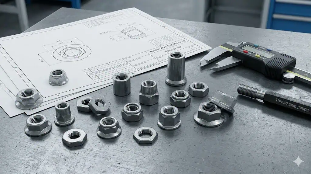
Figure 1: Made-to-print special nuts may include flange nuts, lock nuts, weld nuts, sleeve nuts, thin nuts and other application-specific forms. The manufacturing route should follow the approved drawing, not only the visible shape of the sample.
Term
Requirement Source
Typical Use
Buyer Risk
Standard Nut
Catalog or recognized dimensional standard
When existing thread, shape, material and finish meet the project
Low if correctly matched; high if selected by thread size only
Special Nut
Application-specific geometry or function
When the joint needs flange, locking, sleeve, weld, projection or low-profile features
Requires application review, not only price comparison
Custom Nut
Buyer drawing, sample, 3D file or marked dimensions
When standard nuts cannot satisfy geometry, strength, coating or assembly needs
Needs DFM, sample approval and inspection plan
Made-to-Print Nut
Controlled engineering drawing and revision
Automotive OEM / ODM projects where production must follow approved print
Incomplete drawings can cause tooling errors, inspection disputes and batch inconsistency
What Information Should a Special Nut Drawing Include?
A usable special-nut drawing package should define the product geometry, thread system, material and mechanical requirements, surface-treatment condition, inspection basis, revision status, and the interfaces that affect the real joint.
For automotive RFQs, overall height and nominal thread size are not enough. The supplier needs to know which file controls, which dimensions are critical, which datum structure is used, and in what manufacturing state the dimensions apply. Thread pitch and tolerance class, lead-in chamfer, bearing-face perpendicularity, flange or sleeve geometry, weld-projection position, and coating allowance can affect assembly start, preload, weld performance, gauging, and service access.
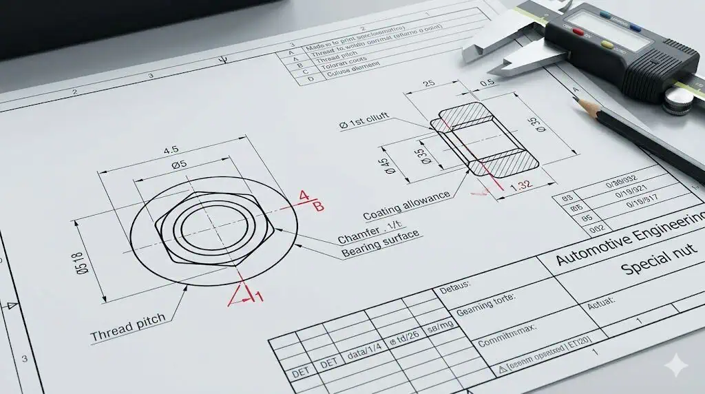
Figure 2: A practical special nut drawing should identify thread pitch, tolerance, chamfer, bearing surface, coating allowance and CTQ dimensions. These fields affect quotation accuracy, tooling review, sample approval and final inspection.
Special Nut Drawing Package Checklist
Document authority: identify the controlling 2D drawing, 3D model, referenced specifications, drawing number, revision, approval status, and the rule to follow if files conflict.
Thread callout: define thread system, nominal size, pitch, direction, tolerance class, engagement or depth where relevant, and the final gauging condition.
Datum and geometry scheme: define datums and only the geometric controls needed for function, such as bearing-face perpendicularity, thread-axis relationship, flange runout, projection position, or sleeve concentricity.
Critical characteristics: identify CTQ, special, safety, or customer-designated characteristics and connect them to an inspection or control method.
Dimensional state: state whether dimensions apply before or after heat treatment, coating, welding, clinching, or another process that may change the final condition.
Material and mechanical requirements: specify the material grade or approved equivalence route, nut property class where applicable, heat treatment, proof-load or hardness requirements, and any material evidence required.
Surface-treatment system: define the coating code or referenced coating specification, conversion layer, sealer, topcoat, lubricant, color if functional, and the required post-coating thread condition.
Functional requirements: where relevant, define prevailing torque, torque/clamp-force test, torque-out, pull-out, push-out, weld performance, electrical contact, sealing, or reuse limits with an identified method and acceptance criterion.
Inspection and sampling basis: identify the measurement method for disputed or critical characteristics and reference the applicable inspection level, control plan, or customer requirement rather than assuming every feature needs 100% inspection.
Change control: define the latest approved revision and how changes to material, tooling, manufacturing location, heat treatment, coating source, or inspection method are submitted when customer approval is required.
Drawing, 3D Model and Referenced Specifications Must Work Together
A 2D drawing is usually the most practical place for tolerances, thread class, material, finish, inspection notes and revision control. A 3D model may control complex geometry. Material, coating, testing and customer-specific requirements may be controlled by referenced specifications. The supplier should not guess which source takes precedence. The RFQ package should identify the governing record and resolve any conflict before quotation or tooling.
Engineering Warning: “M8 Nut” Is Not an Inspectable Specification
A nominal thread size does not define pitch, tolerance class, nut height, bearing face, chamfer, material, property class, coating system, or final inspection condition. A supplier can quote an “M8 special nut” quickly, but the parties may be pricing different products. Clarify the controlled drawing package and acceptance basis before comparing quotations.
Drawing Item
Why It Matters
What Can Go Wrong If Missing
Buyer Action
Thread pitch and tolerance
Controls thread fit, assembly torque and gauge acceptance
Wrong pitch, tight thread, cross-threading or rejection
Define thread standard and final gauge requirement
Chamfer and lead-in
Controls assembly start, thread engagement and service handling
Hard starting, damaged first thread or poor assembly speed
Mark chamfer dimensions and lead-in direction
Bearing surface
Controls clamp load distribution and preload stability
Uneven seating, local deformation or clamp loss
Define bearing face requirement if critical
Coating thickness
Affects corrosion resistance, friction and internal thread clearance
Thread gauge failure or unstable preload
Confirm coating range and post-coating inspection
Material and hardness
Controls strength, formability and failure mode
Thread stripping, cracking, galling or poor heat treatment response
State material grade and hardness or class requirement
Drawing review CTA: If your drawing does not clearly show thread tolerance, coating allowance, material grade or CTQ dimensions, send the current file for engineering review before sample production.
How Drawings Affect Manufacturing Process Selection
The drawing package helps determine whether the part should be cold formed, machined, or produced through a hybrid route because geometry, material, tolerances, functional features, volume, and final-condition inspection all affect manufacturability.
Cold forming may suit repeatable automotive volume when the geometry and material are formable. CNC machining is useful for development samples, low volume, or local features that are impractical to form. A hybrid route can combine a formed blank with tapping, machining, heat treatment, coating, and special inspection.
The drawing must distinguish functional requirements from unnecessarily tight tolerances. Tight limits on every feature can force a higher-cost process without improving the joint. Conversely, an undefined datum, thread condition, or post-coating requirement can make a low quotation impossible to reproduce in production.
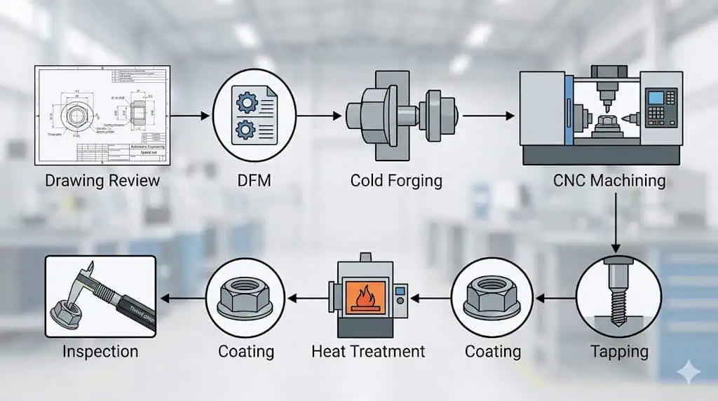
Figure 3: Drawing review, DFM, cold forging, CNC machining, tapping, heat treatment, coating and inspection should be connected as one manufacturing route. If the approved sample route differs from the mass production route, batch risk increases.
Drawing Feature
Likely Process Route
Cost / Lead Time Impact
Validation Needed
Simple formable body, stable volume
Cold forging
Tooling cost applies; unit cost can be stable in volume
Tooling trial, dimensional report, thread check
Complex local feature or prototype stage
CNC machining
Lower tooling barrier; higher unit cost
Dimensional check and function validation
Cold-forged body with special slot, sleeve or face
Hybrid process
More operations; stronger process control required
In-process and final inspection plan
Tight post-coating thread requirement
Process-dependent
May require thread allowance and final gauge review
Post-coating go/no-go gauge inspection
High-strength material or heat treatment requirement
Cold forging or hybrid, depending on geometry
May add heat treatment and hardness control time
Hardness record and material traceability
Typical Engineering Review: Prototype Route Did Not Represent Production
Observed issue: A machined sleeve-nut prototype assembled correctly, but the production-intent cold-formed lot showed burrs and inconsistent internal-thread acceptance after coating.
Why it occurred: The prototype and production routes created different material flow, tapping conditions and finishing effects, while the drawing did not clearly define burr limits or the final thread-gauging state.
Engineering response: Produce and validate a production-intent sample using the planned forming, tapping, heat-treatment and coating sequence. Update the drawing or control plan where the final-condition requirement was ambiguous.
Prevention: Label early CNC parts as geometry or fit-check samples when they do not represent the intended serial process.
Drawing Review Before Quotation: What Must Be Resolved
Before quotation, the buyer and manufacturer should resolve the controlling revision, manufacturing state, unclear tolerances, thread and gauge basis, material and coating callouts, functional requirements, quantity, and approval-document scope.
This review is not an attempt to delay pricing. It separates confirmed requirements from assumptions. A low quotation based on unrecorded assumptions often changes after tooling, coating review, functional testing, or production approval.
Review Point
What the Manufacturer Checks
Risk If Ignored
Required Clarification
Geometry feasibility
Wall thickness, flange, sleeve, projection, undercut and forming direction
Tooling failure, cracking or unstable dimensions
DFM comments before tooling
Thread and gauge feasibility
Pitch, tolerance, depth, tap access and post-coating gauge
Thread rejection or high assembly torque
Thread standard and final inspection method
Material and heat treatment
Formability, hardness, strength class and heat treatment response
Cracking, stripping, brittleness or poor strength consistency
Material grade and hardness requirement
Surface treatment
Coating type, thickness, friction behavior and hydrogen embrittlement risk
Corrosion failure, thread interference or delayed cracking
Finish specification and compliance requirement
Quantity and production route
Sample quantity, trial order, annual volume and launch timing
Wrong process choice or unrealistic lead time
Volume forecast and delivery schedule
Safety Note: Hydrogen-Embrittlement Review Depends on the Nut, Not Only the Mating Bolt
Hydrogen-embrittlement susceptibility depends on the nut’s material, hardness or strength level, residual stress, cleaning and electroplating route, and sustained service stress. The fact that a nut mates with an 8.8 or 10.9 bolt does not by itself establish the nut’s susceptibility. For hardened steel nuts using an electroplated coating, review the exact material condition and process controls under the applicable coating specification before release. For the dedicated risk analysis, see hydrogen embrittlement in high-strength coated nuts.
Why Samples Can Help but Cannot Replace a Manufacturing Drawing
A physical sample can support reverse engineering and fit analysis, but it cannot independently establish the original tolerances, material condition, coating system, functional acceptance criteria, or revision.
Samples are valuable when the original engineering record is unavailable. They can show approximate geometry, assembly direction, contact marks and service wear. However, the measured part may be worn, plastically deformed, corroded, reworked, or coated differently from the original release. Measurement uncertainty and sample-to-sample variation should be considered before assigning new tolerances.
For serial automotive supply, reverse-engineered results should be converted into a controlled drawing package and validated against the mating joint. The buyer should approve the new record rather than treating one measured sample as the universal nominal condition.
Figure 4: A physical sample can help identify approximate geometry and assembly direction, but it cannot reliably define original tolerance, material, heat treatment, coating thickness or revision status. For automotive production, sample data should be converted into a controlled drawing before mass production.
Sample Can Help Confirm
Sample Cannot Reliably Confirm
Drawing Still Needed
General shape and approximate dimensions
Original tolerance and CTQ limits
Critical dimension table and inspection criteria
Assembly direction and visible contact marks
Original preload, nut factor K or service load
Application notes and tightening condition
Thread size by measurement
Original pitch tolerance and final gauge requirement
Thread specification and go/no-go gauge requirement
Visible coating type or color
Coating thickness, corrosion requirement or friction class
Surface treatment specification
Approximate material family
Exact grade, heat treatment and hardness requirement
Material grade and test requirement
Typical Engineering Review: Reverse Engineering Reproduced Shape but Not Strength
Observed issue: A replacement nut matched the sample geometry and passed a basic fit check, but it did not satisfy the required mechanical review.
Why it occurred: The worn sample did not reveal the original material, heat-treatment condition, proof-load requirement, or approved property class.
Engineering response: Reconstruct the drawing with input from the mating bolt, joint load, application owner, available records, and appropriate verification tests before resampling.
Prevention: Use a sample as evidence of geometry and interface—not as the sole source of nominal dimensions and mechanical requirements.
Quality Control Requirements Defined by Drawings
The approved drawing package defines what must be verified, while the control plan or purchase specification can define sampling frequency, records, reaction plans, and submission requirements.
Quality control should follow the actual failure mode and final part condition. A GO/NO-GO thread gauge can confirm whether an internal thread lies within its functional size limits, but it does not by itself prove every thread characteristic, clamp force, prevailing torque, weld performance, or long-term process capability. Hardness supports heat-treatment verification but does not replace proof-load or application-specific functional testing when those are required.
Figure 5: Made-to-print special nut inspection should follow the drawing. Thread gauge inspection, hardness testing, coating thickness measurement and dimensional reports help confirm whether the approved sample can be repeated in production.
Thread size, pitch, tolerance and post-coating fit
Thread gauge record
Hardness testing
Hardness tester
Heat-treatment consistency or a specified hardness requirement; not a substitute for proof-load or joint-function validation.
Hardness report, with proof-load or other functional evidence when required by the drawing or project.
Coating thickness
Coating thickness meter
Surface treatment and thread allowance
Coating report
Salt spray test
Salt spray chamber when specified
Corrosion resistance requirement
Salt spray report if required by drawing or customer specification
Production approval records
Control plan, process flow, PPAP-related documents if required
Automotive launch and revision control
Agreed document package before sample approval
Acceptance Method Must Match the Characteristic
Do not place a generic “inspect all dimensions” note on the drawing and assume it resolves the inspection plan. Critical dimensions, attribute gauges, material tests and functional tests need suitable methods and acceptance criteria. Sampling frequency, capability studies and reaction plans are often better controlled in the quality plan or customer-specific requirement than crowded into the part drawing.
Typical Engineering Review: Final Coating Condition Was Not Defined
Observed issue: A zinc-nickel-coated nut met appearance and corrosion requirements, but the internal thread did not accept the specified gauge after plating.
Why it occurred: The engineering record did not state the coating build allowance or whether the thread acceptance applied before or after final coating.
Engineering response: Clarify the coating system, thread tolerance strategy and final gauging condition, then repeat assembly validation with the specified mating fastener.
Prevention: Treat coating and thread acceptance as linked functional requirements rather than independent drawing notes.
Common Drawing Problems That Cause Custom Nut Project Delays
The most disruptive drawing problems are conflicting source files, missing thread or final-condition requirements, uncontrolled revisions, blanket tight tolerances, and notes that name a finish or test without defining an applicable specification or acceptance criterion.
These gaps are often discovered only after quotation or tooling because the part looks simple. A conflict between the 2D drawing and 3D model can change the geometry; an undefined coating state can change thread acceptance; and unnecessary tight tolerances can increase cost without protecting the joint.
Revision control is especially important in automotive sourcing. The RFQ, sample approval, production tooling, inspection plan and PPAP submission should reference the same approved engineering record. ECR or ECN updates, obsolete files and customer deviations must be resolved before production release.
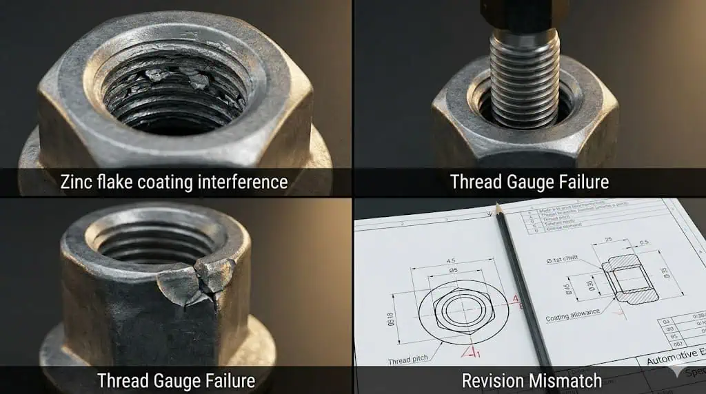
Figure 6: Missing thread tolerance, unclear coating allowance, incomplete projection geometry and uncontrolled drawing revisions can turn a simple custom nut RFQ into repeated sampling, tooling correction and delayed production launch.
Drawing Problem
Project Consequence
Corrective Action
2D drawing and 3D model conflict
Supplier may tool or inspect a different geometry from the buyer’s intent.
Define document precedence and issue a corrected controlled revision before tooling.
Thread pitch, tolerance class or final gauging state missing
Wrong tapping strategy, post-coating rejection, cross-threading or assembly torque problems.
Define the complete thread callout and whether acceptance applies before or after final finish.
Dimensions do not state the manufacturing condition
Heat treatment, coating, welding or clinching may shift the final measured condition.
State the applicable part condition for affected dimensions and tests.
Blanket tight tolerances without functional need
Higher tooling, machining, inspection and scrap cost without a clear joint benefit.
Use functional datums and tolerances supported by the assembly and process capability.
Coating note uses only a color or generic finish name
Different coating systems can produce different corrosion, friction, hydrogen-risk and thread-fit outcomes.
Reference the approved coating specification, system, lubricant/topcoat condition and acceptance basis.
Drawing revision or deviation status is uncontrolled
Quotation, sample, PPAP and production can follow different requirements.
Confirm drawing revision, ECR/ECN status, deviations and obsolete-file control before release.
Application interface is missing
The nut may fit alone but fail with the real bolt, washer, panel, tool access or welding process.
Provide the relevant mating component, joint condition and functional test requirement.
Typical Engineering Review: Weld-Nut Drawing Controlled the Part but Not the Interface
Observed issue: A weld-nut sample matched its external dimensions, but torque-out and pull-out results were unstable after installation.
Why it occurred: The nut drawing did not adequately connect projection geometry with panel thickness, material condition, electrode setup, weld parameters and post-weld thread protection.
Engineering response: Define the controlled interface and qualification responsibility, then validate the installed joint with the agreed test method.
A complete RFQ should identify the controlling engineering record, unresolved assumptions, application interfaces, approval scope, production volume, and commercial timing so the supplier can price the intended part rather than a guessed version.
Made-to-Print Special Nut RFQ Checklist
Controlled 2D drawing: include drawing number, revision, approval status, critical characteristics and referenced specifications.
3D model: provide STEP or another agreed format when it controls complex geometry; state whether the drawing or model takes precedence.
Sample information: identify whether the sample is original, worn, reworked, coated, or supplied only for interface reference.
Thread definition: provide thread standard, size, pitch, direction, tolerance class, depth or engagement where relevant, and final gauging condition.
Material and mechanical requirements: provide material grade or approved equivalence process, nut property class where applicable, heat treatment, proof-load/hardness requirements and evidence required.
Surface-treatment specification: identify the complete coating system or referenced standard, corrosion requirement, friction/lubrication condition and post-coating thread acceptance.
Application interface: provide mating bolt or stud, washer, panel thickness, weld or clinch condition, assembly tool, torque/preload target, environment and service access where they affect the design.
Inspection and functional validation: identify required dimensional layout, gauge records, material/coating evidence, prevailing torque, torque/clamp-force, torque-out, pull-out or other tests only as applicable.
Automotive approval scope: state PPAP level, IMDS, customer-specific requirements, traceability, packaging and change-notification expectations when required by the program.
Commercial inputs: include development quantity, production-intent sample quantity, annual volume, launch timing, tooling ownership, forecast and delivery requirement.
RFQ CTA: If your drawing is incomplete, send the available drawing, sample photo, thread size, material, finish and application position. The missing information can be reviewed before quotation or tooling.
What Drawing-Review Capability Should a Manufacturer Demonstrate?
A capable made-to-print supplier should be able to identify missing or conflicting drawing information, explain the proposed production route, define how final-condition characteristics will be verified, and separate prototype evidence from serial-production approval.
This page focuses on drawing control rather than a complete supplier audit. For broader evaluation of capacity, quality systems, subcontracted processes, traceability and change control, use the automotive special-nut supplier selection guide.
Figure 7: A capable drawing-based special nut manufacturer should combine engineering drawing review, DFM, cold forging or CNC process selection, tapping, coating coordination, inspection and batch traceability before shipment.
Supplier Capability
Question to Ask
Red Flag
Preferred Evidence
Drawing review
Can they mark critical dimensions and missing information?
Quotes immediately without technical review
Marked drawing comments or RFQ clarification list
DFM capability
Can they explain cold forging, CNC or hybrid route?
Uses one process for every geometry
Process route recommendation
Thread and tolerance control
Can they define inspection after tapping and coating?
No final thread gauge plan
Thread gauge record
Surface treatment control
Can they review coating thickness and thread allowance?
Treats coating only as color
Coating report and post-coating inspection plan
Sample and mass production control
Can they separate prototype sample from production-intent sample?
Assumes CNC sample equals mass production approval
Sample approval and control plan
Documentation support
Can they support agreed inspection reports or PPAP-related documents if required?
The applicable standard depends on the drawing, thread system, material, coating route, functional requirement and customer program. A standard should support a specific requirement; it should not be listed as a generic authority signal.
ISO 965 metric thread tolerance series: supports tolerance-system and limit-of-size references for ISO general-purpose metric threads. Confirm the edition and part required by the project.
ISO 898-2:2022: specifies mechanical and physical properties for qualifying non-alloy and alloy steel nuts within its scope. It does not by itself define corrosion, weldability, prevailing torque or joint clamp-force performance.
ISO 3506-2:2020: covers mechanical and physical properties of corrosion-resistant stainless-steel nuts within its scope.
ISO 4042:2022 and its applicable amendments: covers electroplated coating systems for steel fasteners, including dimensional considerations and hydrogen-embrittlement risk reduction.
ISO 16047: provides conditions for torque/clamp-force testing when that functional relationship is part of the project requirement.
ISO 2320:2015: supports functional-property testing for prevailing-torque steel nuts within its scope.
AIAG PPAP: applies when the customer or automotive program requires production-part approval evidence. Submission level and document scope should be confirmed before sample development.
Where the drawing references an OEM, Tier 1 or customer-specific standard, that controlled requirement may add to or override general industry practice. Confirm current revisions and contractual precedence before quotation and production release.
FAQ About Made-to-Print Special Nuts and Drawings
What does made-to-print mean for a special nut?
It means the nut is manufactured and accepted against a controlled engineering record, normally including a 2D drawing and any referenced 3D model, material, coating, test or customer specifications. “Made-to-print” describes the control basis, not one particular nut shape.
Is a 3D model enough to manufacture a custom nut?
Usually not by itself. The model may define geometry, but thread tolerance, material, mechanical property class, heat treatment, coating, critical characteristics, inspection method and revision authority normally require a 2D drawing or referenced specifications.
What should control if the 2D drawing and 3D model disagree?
The buyer must define document precedence and issue a corrected controlled revision before tooling or production. The supplier should not choose whichever file is easier to manufacture.
Can a physical sample replace a manufacturing drawing?
A sample can support reverse engineering and interface review, but it may be worn, deformed, reworked or coated differently from the original part. It cannot reliably establish original tolerances, material condition, acceptance criteria or revision status.
Should thread and coating requirements be checked in the final condition?
Yes when heat treatment, coating, welding or another process can change fit or function. The engineering record should state whether dimensions and gauge acceptance apply before processing, after final coating, after installation, or at more than one stage.
What should buyers send for a made-to-print special nut RFQ?
Send the latest approved drawing, 3D model if applicable, sample information, thread definition, material and coating specifications, mating-part and application data, quantity, launch timing, required tests, and automotive approval documents when required.
Send Your Drawing for Made-to-Print Special Nut Review
Prepare the latest approved drawing, 3D model if applicable, sample information, thread callout, material and coating specifications, application interface, quantity, and required validation documents before quotation.
Request engineering review before tooling or production-intent sampling. The review should identify missing requirements, document conflicts, final-condition inspection needs, and whether the proposed cold-forming, machining, or hybrid route can reproduce the approved record.
This page is written for automotive sourcing, design, supplier-quality and manufacturing teams reviewing drawing-controlled special nuts. It focuses on engineering-record authority, thread and datum definition, manufacturing state, process selection, reverse-engineering limits, final-condition inspection and revision control.
Final requirements must follow the approved drawing package, contractual specifications, mating joint, customer-specific requirements and qualified engineering validation. The article supports RFQ preparation; it does not replace formal design authority, customer approval or a project-specific control plan.