Quick Answer: How Do Custom Special Nuts Move from OEM Drawing to Mass Production?
Custom special nuts for automotive OEM programs are drawing-controlled components developed for a defined joint, assembly process and approval route. The engineering work extends beyond reproducing a non-standard shape. Before tooling or production release, the buyer and supplier need to align the drawing revision, thread and gauging condition, material and property class, forming route, heat treatment, coating, functional validation, PPAP scope, traceability and change-control rules. The most common launch problems occur when a prototype is approved without confirming the production-intent process, or when coating, thread fit and torque behavior are reviewed as separate topics rather than as one bolted-joint system.
Automotive OEM NutsMade-to-Print NutsDFM ReviewProduction-Intent SamplesPPAP When RequiredMass Production Control
Custom special nuts are nuts developed to an OEM, Tier 1 or Tier 2 engineering record rather than selected directly from a catalog. The drawing may define a special flange, sleeve, projection, bearing face, locking feature, thread depth, chamfer, coating system or inspection condition. In other cases, the outside shape looks conventional but the controlled requirements—such as fine pitch, post-coating gauging, proof-load basis, friction window or traceability—make the part application-specific.
The nut must be treated as one element of the complete joint. Its performance depends on the mating bolt or stud, clamped material, washer or bearing surface, coating and lubricant, tightening strategy, service temperature, vibration and corrosion exposure. A thread that passes before coating may fail after final finish; a prevailing-torque feature that meets a dimensional drawing may still produce unacceptable clamp-load scatter; and a weld nut that looks correct may not meet the required torque-out or push-out performance on the buyer’s actual sheet metal.
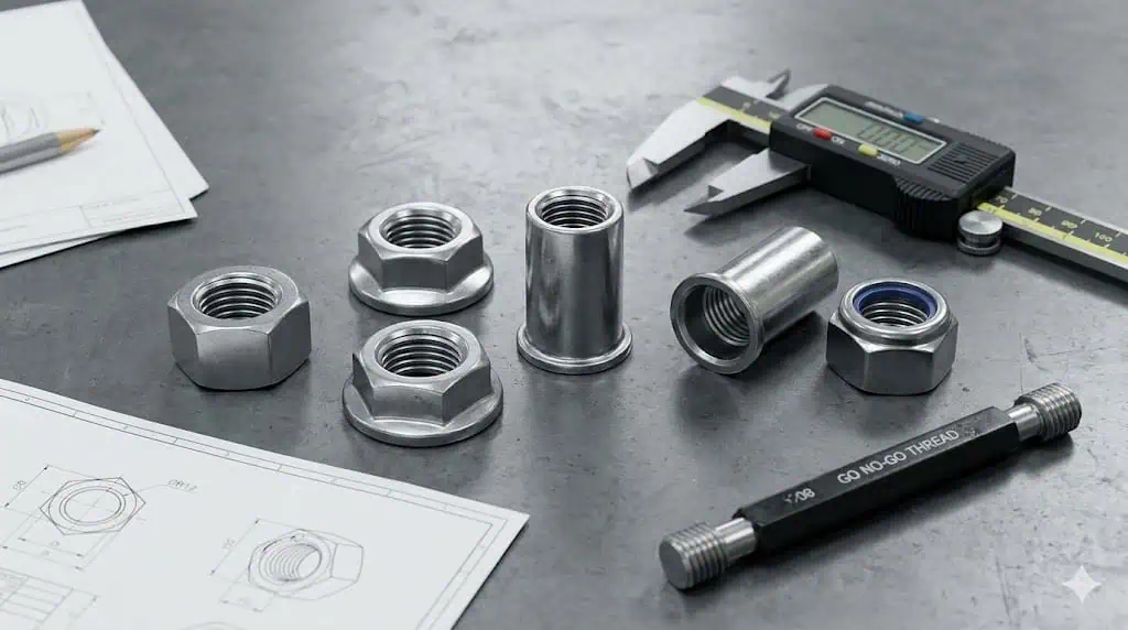
Figure 1: A custom nut should be classified by joint function and controlled characteristics, not by appearance alone. Geometry, thread condition, material, coating and validation method determine whether an existing standard, a modified standard part or a fully made-to-print nut is appropriate.
Development Route
When It Fits the Project
Engineering Work Still Required
Primary Buyer Risk
Standard catalog nut
An available standard part already meets geometry, thread, strength, finish and assembly-space requirements.
Confirm the exact standard, size, property class, coating and mating-joint conditions.
Assuming that matching nominal thread size proves functional suitability.
Modified standard nut
The base geometry is suitable, but one or more features such as finish, height, flange or locking behavior must change.
Validate the modified feature, final thread condition and any effect on torque or assembly.
Underestimating a change that affects tooling, gauging, friction or performance.
Fully custom special nut
The joint needs application-specific geometry, manufacturing features, functional performance or approval records.
DFM, production-route selection, validation plan, tooling control, approval records and change management.
Approving a prototype that does not represent the released production process.
Do Not Customize Before Checking the Standard Route
Unnecessary customization adds tooling, minimum-order pressure, validation work and supply risk. Before creating a new part, compare the joint requirement against an available standard or modified standard nut. Sunhyings’ standard nut vs custom nut selection guide covers that decision in more detail.
From Design Requirement to RFQ: What OEM Buyers Should Prepare
A useful RFQ must describe both the part and the system in which it will operate. A photo and a nominal size such as “M8 nut” are insufficient because they do not define pitch, tolerance, gauge condition, bearing surface, material condition, coating, assembly method or functional acceptance. Missing information normally reappears later as quotation exclusions, repeated samples, tooling changes or delayed approval.
Figure 2: The initial RFQ should link the drawing to the real joint. Thread data, mating hardware, clamped materials, coating, tightening method, annual volume and approval requirements should be available before the manufacturing route is finalized.
Minimum RFQ Inputs
Engineering record: current 2D drawing revision, 3D model where available, physical sample or clearly marked reference dimensions.
Thread definition: thread system, nominal size, pitch, direction, tolerance class, effective depth and required final gauging condition.
Critical characteristics: flange, serration, sleeve, projection, locking zone, bearing face, chamfer, runout, concentricity or other drawing-designated features.
Joint information: mating bolt or stud grade and finish, clamped material, washer condition, available tool access and expected service load.
Material and mechanical requirements: material designation, property class or project-specific proof-load, hardness or metallurgical requirements.
Finish specification: coating system or code, thickness where specified, topcoat or lubricant, appearance limits, corrosion-test requirement and friction requirement where applicable.
Assembly method: tightening tool, torque or torque-angle strategy, lubrication condition, expected clamp force or functional test, or welding parameters for weld nuts.
Program information: prototype quantity, production-intent sample quantity, annual demand, launch timing, packaging and labeling requirements.
Approval scope: dimensional report, material evidence, functional tests, PPAP level or customer-specific documents when required.
Do not assign a generic torque solely from thread size. Torque-to-clamp-force behavior changes with thread friction, bearing friction, coating, lubricant and the mating components. Where clamp-force control is important, define the real test assembly and validation method rather than relying on an assumed nut factor.
Engineering Review Before Tooling: DFM for Special Nuts
Design for manufacturing review asks a stricter question than “Can this shape be made?” It asks whether the nut can be formed, threaded, heat treated, coated, inspected and assembled repeatedly at the intended production rate. DFM should be completed before tooling release because late changes to a projection, wall thickness, undercut, thread depth, bearing face or coating allowance can invalidate both the tool and the approval schedule.
Figure 3: DFM review should identify which dimensions are formed, machined, threaded or affected by heat treatment and coating. Critical characteristics also need a practical measurement method and a defined process stage for acceptance.
Uneven seating, local surface damage, tool interference or clamp-load scatter.
Mark the functional contact surfaces and inspection datum scheme on the drawing.
Projection or weld feature
Projection geometry, sheet thickness and material, electrode access, fixture support and the customer’s performance test.
Spatter, thread damage, incomplete fusion or unstable torque-out, push-out or pull-out results.
Validate the nut, panel and welding schedule as a system.
Cold-forming feasibility
Material formability, reduction sequence, wall thickness, corner radii, extrusion ratio and tool access.
Cracking, laps, incomplete fill, high tool wear or an uneconomic multi-station route.
Permit controlled DFM changes before the drawing and tool are frozen.
Heat treatment and distortion
Required property class, hardness or proof-load basis, dimensional change and post-treatment inspection.
Out-of-round threads, excessive hardness, insufficient proof strength or unstable dimensions.
Define which characteristics are checked before and after heat treatment.
Final coating condition
Coating code, thickness, lubricant or topcoat, final thread allowance and acceptance after the complete finish.
Go/no-go gauge failure, high drive torque, altered prevailing torque or inconsistent clamp load.
Place final functional gauging and assembly checks after the completed coating process.
A Dimensionally Correct Drawing Can Still Be Process-Unstable
Deep internal threads, sharp undercuts, thin walls, narrow bearing faces and unnecessarily tight non-functional tolerances can make tooling, tapping, heat treatment or inspection unstable. The DFM review should distinguish characteristics that protect function from dimensions that only increase manufacturing difficulty.
Choosing the Manufacturing Route: Cold Forming, CNC Machining or a Hybrid Process
The correct route depends on geometry, material, tolerance, development stage and volume. Cold forming is often suitable for repeat automotive volume and can provide efficient material use, but the design must fit the forming sequence. CNC machining is valuable for low-volume development or features that are difficult to form. A hybrid route combines a formed blank with tapping, turning, milling, slotting, welding or another secondary operation.
The critical buyer question is whether the submitted sample represents the intended production route. A CNC-machined geometry sample can confirm fit and packaging, but it does not automatically validate cold-forming flow, production tapping, heat-treatment distortion, coating buildup or high-rate inspection.
Figure 4: A production-intent route connects drawing review, tool or process development, forming or machining, threading, heat treatment where required, final coating, validation, approval and lot-controlled production.
Typical Launch Risk: The Prototype Route Did Not Represent Production
A common failure pattern begins with a manually deburred CNC sample that assembles correctly. The released part is then moved to cold forming, production tapping and barrel coating. The first production lot fails final thread gauging because the forming allowance, tapping wear and coating buildup were not validated together. The appropriate corrective action is not simply to “open the thread.” The team should confirm the released process, thread tolerance strategy, coating condition, final gauge, assembly test and control-plan reaction before resubmission.
Route
Most Suitable Use
Development Advantage
Limitation to Manage
Cold forming
Repeat medium- or high-volume parts with formable geometry.
Production efficiency, material utilization and repeatable blank geometry when tooling is stable.
Tooling investment, forming limits, tool wear and the effect of later heat treatment or coating.
CNC machining
Prototype work, low volume, difficult local features or early geometry validation.
Fast design iteration and flexibility without dedicated multi-station forming tools.
Higher unit cost, burr control, material-flow differences and poor scalability for some programs.
Hybrid process
Formed body with secondary machining, tapping, slotting, welding or special finishing.
Balances production economics with local feature control.
More transfer points, suppliers and process interactions require stronger traceability and control plans.
Material, Mechanical Properties, Heat Treatment and Coating Must Be Reviewed Together
Material and finish decisions cannot be separated from the mating fastener and assembly method. Carbon or alloy steel nuts may use property classes under ISO 898-2 where the nut design falls within the standard’s scope. Corrosion-resistant stainless steel nuts use the grade and property-class framework of ISO 3506-2 where applicable. A custom shape may still require project-specific testing when its geometry falls outside the assumptions of a standard product style.
Hardness is a useful process indicator, but it is not a substitute for proof-load or functional compliance. Likewise, a coating name does not define coating thickness, conversion layer, topcoat, lubricant, friction behavior or corrosion acceptance. The drawing or purchase specification should define the system and test condition that matter to the joint.
Figure 5: The coating decision should account for corrosion exposure, final thread fit, friction, assembly equipment and material condition. Salt-spray duration alone does not predict service life, and coating families should not be treated as interchangeable without customer approval.
Decision
Engineering Question
Evidence or Validation
Common Error
Material
Does the material provide the required strength, formability, corrosion behavior and temperature capability?
Drawing designation, material certificate and applicable chemical or metallurgical verification.
Using a commercial grade name without confirming the governing material specification.
Property class or mechanical requirement
Can the nut safely mate with the specified bolt or stud and sustain the required joint load?
Applicable standard scope, proof-load or customer-defined mechanical testing and mating-fastener review.
Matching only the nominal thread or checking hardness alone.
Heat treatment
Is heat treatment required, and how will it affect threads, dimensions and brittleness risk?
Approved process route, lot records, hardness and mechanical tests where required.
Applying a generic heat-treatment recipe without validating the final nut geometry.
Coating system
What corrosion, dimensional, friction and appearance functions must the coating provide?
Coating designation, thickness or mass where specified, topcoat/lubricant, corrosion test and final thread checks.
Specifying only “zinc,” a color or a salt-spray target.
Assembly behavior
Does the final finish produce acceptable clamp-force, drive-torque or prevailing-torque behavior with the actual mating components?
Defined torque/clamp-force or functional test using the released joint stack.
Reusing the same torque after a coating or lubricant change without validation.
Typical Coating Risk: Corrosion Target Met, Thread and Assembly Failed
A zinc-nickel finish may satisfy a corrosion specification yet still create excessive assembly torque if the internal-thread allowance, lubricant and final gauging condition are not aligned. The prevention is to define the complete coating system, inspect the thread after final finish and validate the nut with the released mating bolt. Sunhyings’ automotive nut coating comparison covers the coating-selection boundary in more detail.
Galling and Hydrogen Embrittlement Are Different Failure Mechanisms
Stainless-thread galling is associated with adhesion and material transfer under high contact pressure, particularly with dry, high-speed stainless-on-stainless assembly. Hydrogen embrittlement is a different risk affecting susceptible higher-strength materials under particular material, process and loading conditions. Electroplating, cleaning, hardness, relief treatment and customer requirements must be reviewed together. For a focused buyer checklist, see hydrogen embrittlement risk in high-strength coated nuts.
Sample Development and Production-Intent Validation
Sample approval should answer two separate questions: does the design fit and function, and can the released production process reproduce it? A geometry prototype may answer the first question. A production-intent sample should use the planned material, tooling concept, forming or machining route, thread process, heat treatment, coating and inspection sequence closely enough to support production approval.
Figure 6: Sample validation should connect drawing characteristics with measurement evidence and real functional checks. The test plan depends on the nut type; not every project requires the same inspection package.
Validation Area
Typical Check
Important Boundary
Release Evidence
Dimensions and geometry
Critical dimensions, datum relationships, flange, sleeve, projection, chamfer and bearing face.
Measurement method and sample size must suit the tolerance and production process.
Ballooned drawing and dimensional report where required.
Internal thread
Thread system, pitch, effective depth and go/no-go or other specified gauge after final finish.
A gauge result does not by itself prove clamp-force or prevailing-torque performance.
Gauge calibration status and recorded inspection results.
Mechanical performance
Proof load, hardness or project-specific functional test as applicable.
The applicable requirement depends on material, geometry and standard scope.
Test report linked to sample and material lot.
Coating and corrosion
Coating designation, thickness or mass, appearance, corrosion test and final thread condition.
Laboratory corrosion tests compare coating systems under defined conditions; they do not directly predict vehicle life.
Coating report and test method/acceptance criteria.
Joint function
Torque/clamp-force, prevailing torque, weld torque-out/push-out/pull-out, retention or real assembly fit.
Use the actual or formally representative mating components and assembly condition.
Functional validation record and approved test setup.
Typical Weld-Nut Risk: Projection Geometry Was Approved Without the Panel
A weld nut can pass visual and thread inspection but fail torque-out or push-out testing when its projection pattern is not compatible with the panel thickness, sheet material, electrodes, fixture and welding schedule. The solution is joint-level development rather than changing the nut in isolation. For a dedicated review, see projection weld nut design and validation.
PPAP and Production Approval: Define the Scope Before Sampling
PPAP is not automatically required for every custom nut order, and the submission level should not be assumed. Automotive customers may require PPAP or another approval package based on their own sourcing rules, part risk and customer-specific requirements. The scope should be agreed before samples are made so that production-intent parts, records and measurement evidence are generated by the correct process.
The value of PPAP is not the volume of paperwork. It is the evidence that the supplier understands the engineering record and can meet it with the released production process at the required production conditions. AIAG describes PPAP as a process for demonstrating that engineering design records and specification requirements are consistently met during an actual production run.
Approval Element
Buyer Must Define
Supplier Must Demonstrate
Frequent Gap
Engineering record
Released drawing revision, specifications, special characteristics and approved deviations.
Parts and records correspond to the same approved revision.
Samples were made from an obsolete drawing or undocumented interpretation.
Production process
Whether production-intent tooling, rate and source are required for submission.
Process flow and actual manufacturing route match the submitted parts.
A prototype or manually corrected sample is submitted as representative production.
Control plan and reaction plan
Customer-specific requirements and designated critical characteristics.
Control method, frequency, responsibility and reaction for nonconforming results.
Final inspection is listed, but process drift and containment actions are undefined.
Measurement and capability
Required studies, sample size and acceptance criteria.
Measurement method is suitable and production capability evidence is valid for the released process.
Capability numbers are quoted without a stable process or adequate measurement system.
Material, coating and functional records
Applicable certificates, tests and customer formats.
Records are linked to the submitted lot and approved sources.
Generic supplier reports cannot be traced to the sampled parts.
Change approval
Which changes require notification or resubmission.
No unapproved changes to material, source, tool, process, heat treatment, coating or location.
Commercially “equivalent” changes are made without customer review.
Mass Production Control: Keeping the Approved Process Stable
Approval is the start of production control, not the end. Lot consistency depends on incoming-material identity, tooling condition, threading, heat treatment, coating, inspection, segregation, packaging and controlled change. The reaction plan is especially important: it should define what happens when a thread gauge, hardness test, coating result or critical dimension moves outside the approved limit.
Production Control Point
Practical Control
Required Traceability Link
Risk if Weak
Material and incoming lot
Approved material source, lot identity and receiving verification.
Raw-material lot or heat to production batch.
Mixed material or inability to contain a suspect lot.
Tooling and forming
Tool-life limits, first-off checks and in-process monitoring of critical geometry.
Tool set and production time to batch record.
Gradual drift in projection, flange, height or bearing surface.
Thread production
Tap or thread-tool condition, burr control and defined gauge frequency.
Threading operation and gauge results to batch.
Intermittent thread failures hidden by final sampling.
Heat treatment
Approved source, batch parameters and required mechanical verification.
Heat-treatment batch to nut production lot.
Hardness or mechanical-property variation that cannot be isolated.
Coating
Approved coating source and code, bath or lot control, final thread and functional checks.
Coating batch and test report to shipment lot.
Corrosion, friction or dimensional variation between deliveries.
Inspection and measurement
Calibrated equipment, suitable measurement system, sampling plan and reaction plan.
Inspection record to released lot and drawing revision.
Data exists but cannot prove which shipment or revision it represents.
Sorting, packaging and labeling
Mixed-part prevention, thread protection, quantity control and lot labels.
Carton or container identity to production and shipping records.
Correct parts are mixed, damaged or lose their lot identity after final inspection.
Traceability does not prove that a design is suitable, but it allows a suspect material, process or coating lot to be contained and investigated. For the record chain from material through shipment, see traceability for automotive fasteners.
Common OEM Development Risks and the Correct Prevention Point
Most project failures begin earlier than the point at which they are discovered. A thread rejection after coating may originate in the RFQ or DFM stage. A PPAP delay may originate when the sample route was not defined. A field loosening concern may originate when coating friction and clamp force were not validated with the complete joint.
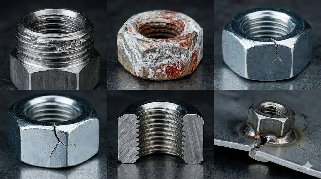
Figure 7: Failure analysis should identify the earliest control point that could have prevented the issue. Visual inspection alone cannot control thread fit, clamp force, prevailing torque, weld performance, hydrogen-related risk or process traceability.
Observed Problem
Likely System Cause
Best Prevention Stage
Required Action
Production lot fails after a successful prototype
Prototype and production routes were not equivalent.
Sample planning
Define geometry samples and production-intent samples separately.
Thread gauge or assembly failure after coating
Final finish, thread allowance and inspection stage were not aligned.
Drawing and DFM review
Specify final coating condition and validate with the mating fastener.
Prevailing torque varies between lots
Locking feature, coating, lubricant, thread process or mating bolt changed.
Functional validation and control plan
Control the full test configuration and change notification.
Weld nut does not meet retention performance
Nut projections, panel and weld schedule were developed separately.
Joint DFM and process validation
Validate on the released sheet material, thickness, electrodes and fixture.
Delayed cracking concern after electroplating
Susceptible material condition and coating process were not assessed together.
Material and coating selection
Apply the customer-specified risk controls, test plan and approved process route.
Problem lot cannot be isolated
Material, heat treatment, coating or packaging records are not linked.
Production planning
Create backward and forward traceability before serial production.
What Evidence Should Buyers Review Before Nominating a Custom Nut Manufacturer?
This page is not intended to duplicate a full supplier-audit guide. For the design-to-production workflow, the buyer should confirm that the supplier can explain the process route, show how critical characteristics will be measured, identify outsourced special processes, support the agreed approval scope and maintain the approved process after launch.
Evidence Area
Buyer Question
Useful Evidence
Warning Sign
Engineering review
Can the supplier identify thread, tooling, coating and functional risks before quoting?
Marked drawing, feasibility notes and an open-issues list.
An immediate price with no questions about the joint or drawing revision.
Process ownership
Which operations are internal, outsourced or approved customer sources?
Process flow, source list and responsibility matrix.
Unclear ownership of heat treatment, coating or functional testing.
Measurement capability
How will each critical characteristic and functional requirement be verified?
Inspection plan, equipment list, gauge strategy and sample report.
Visual approval offered for characteristics that require gauging or testing.
Production-intent validation
Will samples represent production tooling, processes and sources?
Sample-route statement and production trial records.
A CNC prototype is presented as proof of cold-formed mass production.
Automotive documentation
Can the supplier support the customer-defined PPAP and change-control scope?
Agreed document matrix, control plan and traceability example.
Generic “PPAP available” claims without level, timing or responsibility.
Serial-production stability
How are tool wear, special-process lots, mixed parts and changes controlled?
Control records, lot labels, reaction plan and change procedure.
No link between final cartons and material/process records.
Use this final checklist to prevent an incomplete RFQ from moving directly into tooling or serial production.
Gate 1 — Requirement Definition
Current drawing revision and applicable customer specifications are identified.
The nut’s joint function, assembly position and mating components are defined.
A standard or modified standard option has been considered before full customization.
Gate 2 — Feasibility and Quotation
Thread, critical dimensions, material, mechanical requirements, coating and annual volume are complete.
Open DFM issues and proposed drawing changes are documented before tooling.
The quoted route identifies forming, machining, threading, heat treatment, coating, testing and outsourced processes.
Gate 3 — Sample Planning
Geometry prototypes and production-intent samples are clearly distinguished.
The validation plan covers dimensions, thread, mechanical properties, coating and joint function as applicable.
PPAP or customer approval scope is defined before samples are manufactured.
Gate 4 — Production Approval
Submitted samples, inspection data and material/process records use the released production route.
Control plan, measurement method, traceability and reaction plan address critical characteristics.
Any deviation is formally approved and linked to the relevant drawing and lot.
Gate 5 — Serial Production
Tooling, thread process, heat treatment, coating, inspection and packaging remain under the approved controls.
Material, production, special-process and shipment lots can be traced backward and forward.
Material, tooling, process, source, location and coating changes follow the customer’s notification and approval rules.
Applicable Standards and Automotive Approval References
The controlling documents are always the released drawing, customer specifications and customer-specific requirements. The references below support particular aspects of the review; none of them independently defines every requirement for a custom automotive nut.
ISO 898-2:2022: mechanical and physical properties of non-alloy and alloy steel nuts with specified property classes within its scope. It does not replace torque/clamp-force, prevailing-torque, corrosion or weld validation.
ISO 3506-2:2020: grades and property classes for corrosion-resistant stainless steel nuts within its scope.
ISO 2320:2015: functional properties and test framework for prevailing-torque steel nuts within its scope.
ISO 16047: conditions for torque/clamp-force testing of threaded fasteners and related parts.
ISO 4042:2022: electroplated coating systems for fasteners, including dimensional considerations and recommendations for minimizing hydrogen-embrittlement risk; applicable amendments and customer requirements must also be checked.
ASTM F1941/F1941M-16(2025): electrodeposited coating requirements for mechanical fasteners in inch and metric systems.
AIAG PPAP: production part approval framework when required by the customer or automotive program.
What information is required before quoting an OEM custom nut?
Provide the current drawing or sample data, thread specification, critical characteristics, material and mechanical requirements, coating system, mating components, assembly method, validation scope, quantities and launch timing. A nominal thread size and photograph are not enough for a controlled quotation.
Can an automotive custom nut be developed from a physical sample?
Yes, but a sample does not reveal every requirement. Material, heat treatment, coating, thread tolerance, functional performance, drawing revision and customer approval requirements still need to be defined before production release.
What is the difference between a geometry prototype and a production-intent sample?
A geometry prototype confirms shape, fit or assembly access and may use a temporary process such as CNC machining. A production-intent sample should represent the planned material, tooling, manufacturing route, heat treatment, coating and inspection closely enough to support production approval.
Is PPAP required for every automotive custom nut?
No. PPAP requirements, submission level and document scope are defined by the customer or program. They should be agreed before sampling so the submitted parts and records come from the correct production-intent process.
Should internal threads be checked before or after coating?
In-process checks may be required before coating, but final acceptance should address the completed coating condition when coating can affect thread fit or function. The drawing or inspection plan must define the gauge, timing and acceptance criteria.
Does a hardness result prove that a high-strength nut meets its mechanical requirement?
No. Hardness supports process control, but it does not automatically prove proof load, thread-stripping resistance or joint performance. Use the applicable product standard or project-specific mechanical and functional tests.
Can the assembly torque remain unchanged after the coating changes?
Not without review. A coating, topcoat or lubricant change can alter thread and bearing friction, which changes clamp force at the same torque. Validate the released coating and mating components using the specified assembly test.
Send the Drawing Before Tooling or Production-Intent Sampling
For an automotive OEM custom nut review, provide the drawing revision, mating bolt or stud, material and property requirements, coating specification, assembly condition, annual volume and required approval documents. This allows the project team to decide whether an existing nut, modified standard design, cold-formed custom nut, machined prototype or hybrid process is appropriate before tooling is released.
This article addresses the OEM development workflow for custom special nuts: requirement definition, DFM, production-route selection, production-intent samples, coating and thread interaction, customer approval, traceability and serial-production control.
Final material, dimensions, property class, coating, friction condition, test method, PPAP scope and change-control requirements must follow the released buyer drawing, applicable standards and customer-specific requirements. Examples describe common engineering failure patterns and are not claims about a named customer program.