Oxygen Sensor Technical Guide
Understand oxygen sensor replacement cost drivers, labor factors, safe installation steps and the fitment checks required before ordering.

Quick answer
Oxygen sensor replacement involves more than removing a threaded part. First confirm the failed circuit and exact position, then match the OE reference, sensor technology, connector and cable routing. Total cost varies with vehicle access, sensor type, corrosion, local labor rates and whether an underlying wiring, exhaust, fuel-control or catalyst fault also requires repair.
Before replacement: prove the repair direction
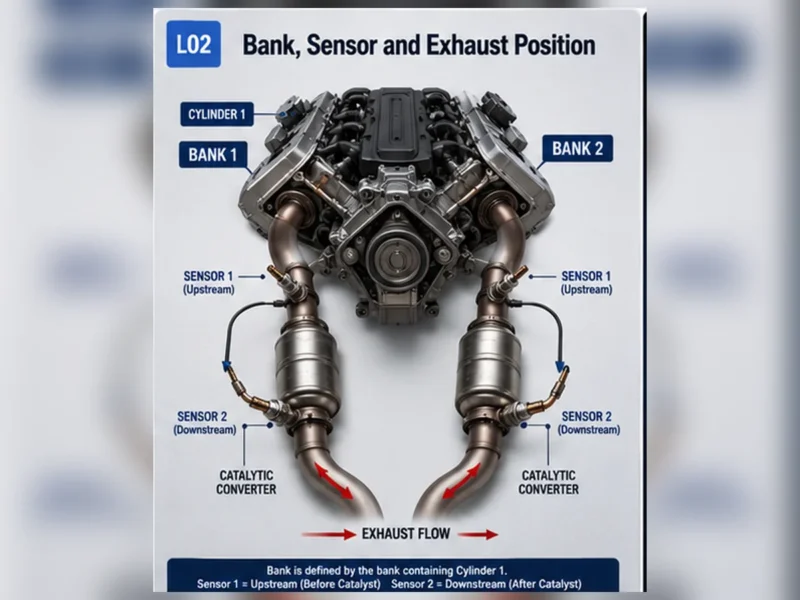
Record codes and freeze-frame data, identify Bank 1 or Bank 2 and Sensor 1 or Sensor 2, inspect the harness, and check for exhaust leaks. For heater faults, test the vehicle-side power, ground and control circuit. For response or mixture codes, compare fuel trims and sensor behavior with service information. Replacing a sensor without these checks can leave the original fault unchanged.
What changes oxygen sensor replacement cost?
| Cost driver | Why it matters |
|---|---|
| Sensor technology | Wideband/A/F sensors and application-specific direct-fit assemblies may cost more than basic narrowband designs. |
| Access location | A reachable manifold sensor and a sensor behind shields or underbody components require different labor time. |
| Corrosion and thread condition | Heat cycling and corrosion can slow removal or require thread repair. |
| Vehicle diagnosis | Electrical, exhaust or fuel-system testing adds time but prevents an unsupported parts replacement. |
| Related damage | A melted harness, exhaust leak or contaminated catalyst may require additional work. |
| Market and labor rate | Parts channels, taxes and shop rates differ by region. |
Use online cost ranges only as planning references. A useful estimate should identify the exact sensor position, part basis, diagnostic allowance and any conditions that could change labor.
How long does replacement take?
There is no reliable universal labor time. Access, corrosion, exhaust temperature, vehicle lifting requirements and connector routing all matter. The service procedure may require shields or other components to be removed. Diagnosis and post-repair monitor verification should be included when comparing estimates.
Safe installation sequence
- Let the exhaust cool and support the vehicle with approved equipment.
- Disconnect the correct connector without pulling the wires.
- Remove the sensor with the specified tool while protecting the exhaust threads.
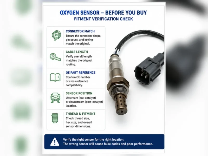
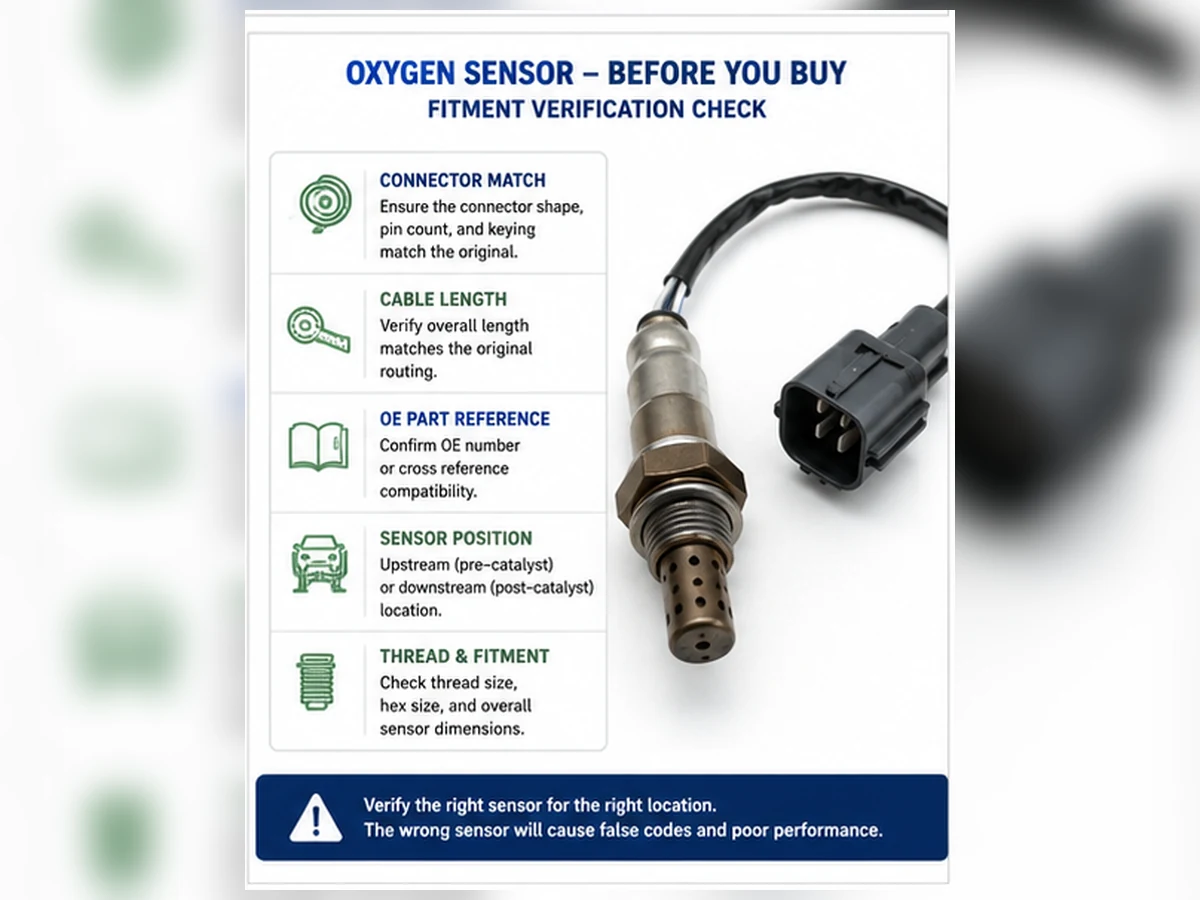
- Compare the old and replacement parts: thread, hex, shield, connector, keying and cable length.
- Route the harness away from heat, sharp edges and moving parts.
- Use the product or vehicle torque instruction. Do not invent a universal torque value.
- Follow the supplier instruction on anti-seize; many sensors are supplied with treated threads.
Post-repair verification
Reconnect all retained clips, check for exhaust leaks, confirm sensor and heater data, and complete the manufacturer’s legal verification procedure. Do not assume that clearing the code proves the repair. Readiness monitors may need defined operating conditions before a result is available.
When professional replacement is the better choice
Use a qualified repairer when safe lifting equipment is unavailable, the sensor is seized, wiring diagnosis is required, the catalyst may be overheating, or service information calls for specialized tests. Emissions-control faults should be repaired, not hidden with a spacer, simulator or software change.
Decide what is actually being replaced
An oxygen-sensor code can describe the sensing circuit, heater circuit, response rate or an implausible signal. The repair may be the sensor, but it may instead be a connector, harness, fuse, exhaust leak or underlying air-fuel fault. Write the proposed repair direction before ordering: exact bank and position, evidence that the vehicle-side circuit works, evidence that the exhaust is sealed and the response test the sensor failed. This record prevents a diagnostic assumption from becoming an unsupported parts order.
| Finding | Likely repair direction | Evidence still required |
|---|---|---|
| Heater has no vehicle-side supply | Fuse, wiring or control diagnosis | Correct diagram, loaded voltage and ground/control test |
| Signal remains biased after mixture and circuit checks | Sensor replacement may be justified | Technology-specific response procedure and operating conditions |
| Lean indication changes after an intake leak is repaired | Air-leak repair | Fuel-trim and sensor response verification |
| P0420/P0430 with plausible sensor operation | Continue catalyst-system diagnosis | Misfire, fuel control, exhaust leakage and catalyst evaluation |
How to compare replacement estimates
A low quote and a high quote may not describe the same work. Ask whether the estimate includes diagnosis, the exact direct-fit sensor, access work, thread-restoration risk, exhaust-leak correction and post-repair monitor verification. Taxes and local rates also vary. This page does not provide a universal dollar range because a range detached from the vehicle, position and market can be more misleading than useful.
Part identity in the estimate
The estimate should identify the part number basis and whether it is upstream or downstream, narrowband or wideband, direct-fit or universal. An OE cross-reference is a candidate mapping, not proof of fit until it is reconciled with full vehicle and emissions data. If the quote says only “O2 sensor,” the scope is incomplete.
Diagnostic and access labor
Diagnostic time establishes whether replacement is justified. Access labor may include shields, undertrays or other application-specific operations. A seized sensor can increase removal time and create a need to restore threads. The repairer should explain contingencies without promising that every corroded part will release normally.
Verification after installation
A complete estimate includes leak inspection, circuit and live-data checks and the applicable monitor procedure. A warning light that is manually cleared is not evidence that the monitor passed. Permanent codes may remain until the control module observes a successful monitor result.
Direct-fit and universal installation paths
| Decision point | Direct-fit sensor | Universal splice-in sensor |
|---|---|---|
| Connector | Application connector is supplied | Approved connector transfer or termination procedure is required |
| Main risk | Wrong application, position or cable routing | Wrong circuit identification, splice quality or environmental sealing |
| Installation rule | Do not cut or alter the direct-fit harness | Follow the sensor manufacturer instructions exactly |
| Selection proof | Verified catalog match and OE/application data | Verified technology, circuit compatibility and approved splice method |
Universal does not mean compatible with every vehicle. Wire colors are not a universal pinout standard. If the circuit cannot be positively identified from reliable instructions, stop rather than experiment on an emissions-control circuit.
Manage removal and thread risks
Cool and support the vehicle
Exhaust components can cause serious burns. Allow adequate cooling and use approved lift points, stands or professional lifting equipment. A jack alone is not a working support. Arrange lighting and tool access before applying force so the harness, nearby lines and the sensor connector remain protected.
Protect the bung and surrounding exhaust
Use the tool and access method specified for the application. Excessive force, impact or uncontrolled heat can damage the bung, manifold, catalyst shell or nearby components. If threads begin to gall or the bung moves, the job has changed from routine replacement to exhaust repair and should be reassessed.
Follow product instructions for thread compound and torque
Some replacement sensors arrive with treated threads. Adding more compound can contaminate the sensing element or change tightening behavior. Torque depends on the sensor and application; use the product or vehicle specification, not a value copied from a different part.
Harness routing is part of the repair
Match the original clip locations and strain relief. The cable must stay clear of the exhaust, shafts, steering, suspension and sharp edges through the full range of movement. Do not stretch a short cable or leave a long cable loop unsupported. Confirm the connector lock and terminal seating rather than relying on an audible click alone.
Post-replacement verification matrix
| Check | Pass evidence | What a failure suggests |
|---|---|---|
| Physical installation | No leak, secure connector, correct clips and heat clearance | Thread, seal, routing or connector problem |
| Heater circuit | Specified supply/control and plausible current or resistance | Vehicle circuit, connector or new-part issue |
| Sensor response | Technology-specific response under valid operating conditions | Wrong part, unresolved mixture fault, leak or sensor concern |
| Fuel control | Fuel trims and commanded state are plausible | Air, fuel, ignition or mechanical root cause remains |
| Monitor result | Applicable monitor completes without the fault returning | Diagnosis or repair requires further review |
Record the before-and-after values. If the same code returns, do not repeatedly replace parts. Reopen the original test path, verify the physical position and check whether a shared circuit or unresolved system condition was missed.
Composite scenario: replacement does not repair missing heater power
Composite engineering scenario: a downstream-sensor heater code leads to an immediate sensor replacement. The code returns because a damaged harness had opened the protected supply. A loaded circuit test, harness repair and restored heat-safe routing correct the condition. This scenario combines common diagnostic patterns; it is not a Sunhyings customer case or product test.
Investigate contamination and repeat failure
A removed sensor can carry evidence of another system problem. Heavy soot can accompany rich operation or misfire; oily deposits can point toward oil consumption; coolant-related deposits can indicate an internal leak; unsuitable silicone products can poison some sensing elements. Appearance alone is not a complete diagnosis, but replacing a contaminated sensor without finding the source can expose the new part and catalyst to the same condition.
Document deposits with clear photos, review oil and coolant consumption, inspect fuel and ignition operation and follow the vehicle procedure. Do not clean a sensing element with solvents or abrasives unless the manufacturer explicitly provides such a method. Most field cleaning attempts cannot restore a calibrated response and may create misleading short-term behavior.
Build a replacement job plan before loosening the sensor
A high-quality replacement plan identifies why the part is being changed, where it is installed, how access will be created, what could be damaged during removal and how the repair will be verified. This prevents the common situation in which the old sensor is removed before the new connector, lead length or technology has been reconciled.
| Planning item | Information required | Why it changes cost or risk |
|---|---|---|
| Diagnostic basis | Failed circuit or response test and competing causes checked | A wrong diagnosis creates repeat labor and may damage the catalyst |
| Exact position | Bank, Sensor number and location in exhaust flow | Access and part identity can differ on the same vehicle |
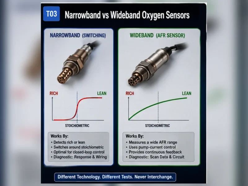
| Sensor technology | Narrowband, titania or wideband/A/F system | Controls electrical compatibility and verification method |
| Access method | Lift points, shields, undertrays and nearby components | Labor and safety depend on actual access |
| Corrosion condition | Thread, bung, manifold and surrounding exhaust condition | Seized threads can convert replacement into exhaust repair |
| Harness route | Connector location, clips, heat clearance and movement | A wrong-length lead can melt, stretch or contact moving parts |
| Post-repair monitor | Required operating conditions and legal verification process | Cleared codes alone do not establish a successful repair |
A useful cost model has more than part and labor
Published price ranges are broad because they combine different vehicles, positions, sensor technologies, labor markets and repair scopes. A direct-fit upstream wideband sensor in a restricted engine bay is not the same job as an accessible downstream narrowband sensor. Instead of presenting one universal total, compare estimates using the same scope.
| Cost component | Questions to ask | Excluded-risk warning |
|---|---|---|
| Diagnosis | Which tests support replacement and are results documented? | A free code read is not a completed diagnosis |
| Replacement part | Which OE reference, position, technology and warranty basis? | “O2 sensor” does not define the part |
| Access labor | Are shields, undertrays or application-specific removals included? | Low estimate may assume ideal access |
| Corrosion contingency | How are seized threads or a damaged bung handled? | No shop can promise every corroded sensor releases cleanly |
| Related repair | Are wiring, exhaust leaks or root-cause faults separate? | A sensor replacement cannot repair those conditions |
| Verification | Are live data, leak checks and monitor completion included? | Turning off the lamp is not the same as passing the monitor |
| Taxes and logistics | Are taxes, freight, mobile service or vehicle recovery included? | Online part price rarely represents completed job cost |
Inspect the replacement before the old part becomes the template
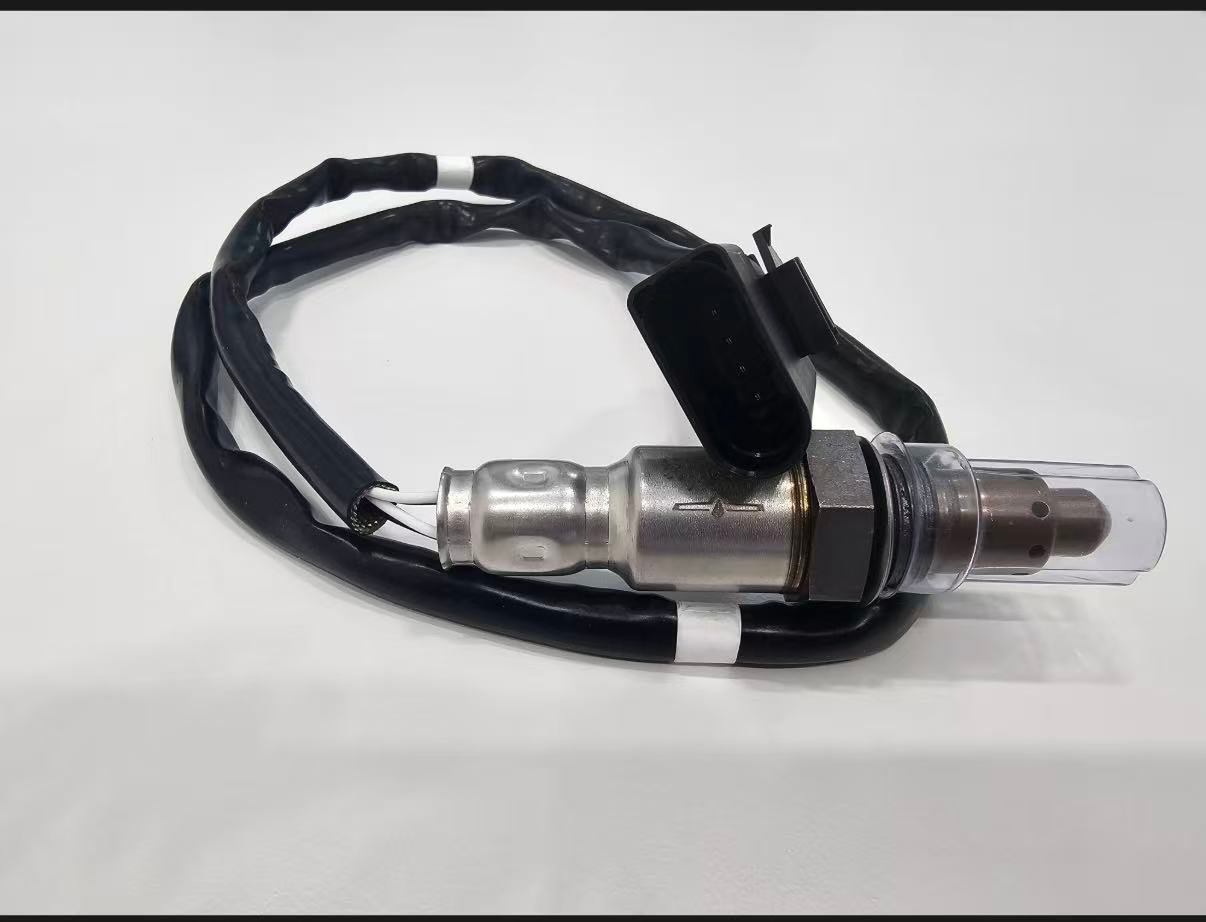
Keep both parts clean and compare them before installation. Use the verified application record as the authority, then use the physical comparison to detect a catalog or packing conflict. Do not assume that a new sensor is correct because the thread starts or the connector shell looks similar.
| Feature | Comparison | Reject or stop condition |
|---|---|---|
| Part and label identity | Supplier part, OE reference candidate, revision and package | Loose unmarked part or label conflict |
| Sensing technology | Catalog and electrical specification | Selected by wire count or appearance only |
| Thread and seat | Diameter, pitch, seat and installed interface | Resistance, incorrect shoulder or sealing mismatch |
| Shield geometry | Length, openings and clearance | Contact with exhaust or application conflict |
| Connector | Housing, keys, lock, pins and terminal layout | Forced engagement, altered keys or pin conflict |
| Cable | Length, insulation, strain relief and clips | Stretching, unsupported loop or heat/motion interference |
| Thread treatment | Product instructions and supplied condition | Adding compound contrary to instructions or contaminating shield |
Removal sequence and decision points
- Preserve evidence. Record codes, freeze frame, readiness, live data and the identified position before power loss or clearing.
- Cool and support. Allow the exhaust to cool and support the vehicle at approved points with equipment rated for the vehicle.
- Disconnect without pulling the lead. Release the connector lock and clips using the service method. Inspect terminals and note routing.
- Choose controlled access. Use the correct sensor socket or wrench and avoid uncontrolled force on the manifold, catalyst shell or bung.
- Stop if the joint changes. If the bung moves, threads gall or the surrounding exhaust cracks, reassess as an exhaust repair rather than forcing completion.
- Inspect removed evidence. Photograph deposits and compare identity, but do not claim the appearance alone proves the root cause.
- Install to exact instructions. Follow product or OEM torque and thread-compound guidance; no universal value is supplied here.
- Restore routing. Refit every heat shield and clip, preserve strain relief and check clearance through component movement.
Post-installation verification is part of replacement
| Verification step | Pass evidence | If it fails |
|---|---|---|
| Visual and leak check | Correct position, secure connector, restored clips and sealed exhaust | Correct installation before interpreting data |
| Heater circuit | Specified supply/control and plausible warm-up behavior | Recheck vehicle circuit, connector and part identity |
| Sensor response | Technology-correct response under valid conditions | Check wrong part, unresolved mixture, leak or circuit fault |
| Fuel control | Trims and commanded state are plausible for operating condition | Continue air, fuel, ignition or mechanical diagnosis |
| Monitor completion | Applicable monitor runs without the fault returning | Review original test path; do not repeatedly change parts |
| Road and safety check | No harness contact, exhaust noise or new drivability concern | Stop and correct physical installation or unresolved fault |
Composite parts case: correct family, wrong exhaust position
Composite engineering scenario: an online listing groups two sensors under one model and year. The ordered part shares thread size and a similar connector but has a shorter lead and different clip locations. Rather than extending the cable, the installer checks engine, emissions configuration and Bank/Sensor position and finds that the listing mapped the other exhaust position. The order is corrected before installation.
The cost avoided is not quantified because no real order data was supplied. The decision lesson is concrete: catalog fitment, physical interface and exact position must agree. This is a composite scenario, not a claim about a Sunhyings shipment.
Composite repeat-repair case: contamination source remains active
Composite engineering scenario: a slow-response sensor is replaced, but the new part later develops similar deposits and response concerns. Review finds ongoing coolant consumption that was not included in the original repair scope. The engine condition is diagnosed and corrected before another sensor and catalyst decision is made.
A removed sensor can provide a clue, but deposit color is not a complete chemical analysis. Oil, coolant, rich operation and unsuitable sealants can affect sensors and catalysts. Document consumption and engine evidence, correct the source and follow service guidance. This scenario is composite and does not imply a universal failure interval.
Record the repair so a future claim can be investigated
- VIN or complete YMME, engine and emissions configuration used for selection
- Exact Bank/Sensor position and verified OE or controlled cross-reference basis
- Supplier part number, package label, lot/date and purchase record
- Codes, freeze frame and diagnostic tests before replacement
- Connector, old-part, new-part and installed-routing photographs
- Torque/thread-treatment source and any access or thread complication
- Post-repair circuit, response, fuel-control and monitor results
Direct-fit versus universal replacement decision
A direct-fit sensor includes an application connector and should be selected from verified application data. Do not cut its harness to overcome a wrong connector or lead length. A universal sensor requires a manufacturer-approved method for identifying and joining the correct circuits while preserving environmental sealing and heat resistance. Universal does not mean one calibration or pinout fits every vehicle.
| Decision area | Direct-fit path | Universal path | Stop condition |
|---|---|---|---|
| Application proof | Current catalog match for vehicle and exact position | Verified technology and circuit compatibility | Only wire count or thread is known |
| Connector | Supplied keyed connector engages without alteration | Approved termination or connector-transfer instructions | Forced key, guessed pinout or twisted/taped joint |
| Lead | Correct length and original-style routing provisions | Length and insulation suitable for approved route | Lead stretched or unsupported near exhaust/motion |
| Installation record | Part and application record | Part, circuit map, splice method and sealing record | No traceable instruction source |
| Regulatory check | Designed emissions function retained | Designed function retained under applicable rules | Any bypass, simulator or monitor defeat |
Analyze a repeat code without assuming the new part failed
If the same code returns, compare the before-and-after evidence. An immediate heater-circuit return points toward an unresolved circuit, wrong part or connector problem more strongly than normal sensor aging. A response or mixture code that returns only under certain load may require renewed leak, fuel or engine testing. A different code can indicate a changed condition rather than the same repair failure.
| Return pattern | First review | Product evidence to preserve |
|---|---|---|
| Code returns immediately key-on or cold | Part identity, pinout, open/short and heater circuit | Package, lot, resistance/current and connector photos |
| Code returns only hot | Heat-related harness movement, exhaust leak and circuit behavior | Installed routing, clearance and hot-condition readings |
| Fuel-control complaint remains | Original air/fuel/ignition/mechanical diagnosis | Response data and before/after fuel trims |
| New catalyst code appears | Mixture, misfire, contamination, exhaust and catalyst path | Correct upstream/downstream part and position identity |
| Physical damage or melted lead | Routing, clips, exhaust movement and application length | Full installed photos, not only the damaged section |
Replacement must preserve emissions monitoring
A sensor replacement is not complete if the harness is altered to conceal a signal, the sensor is moved out of the exhaust stream, or software is used to disable the monitor. Spacers, defoulers, simulators and deletes can mask evidence without correcting the engine, circuit or catalyst and can violate emissions law. Use a lawful part and restore the designed configuration.
Do not promise that any single sensor will make a vehicle pass inspection. Inspection outcome depends on the complete vehicle, readiness, applicable regulation and test procedure. The defensible promise is narrower: supply the verified part identity, install it correctly, correct the diagnosed root cause and document monitor-level verification.
Three estimate scopes that should not be compared as the same job
The examples below are scope comparisons, not price quotations and not Sunhyings service records. They show why an online sensor price cannot be converted into one reliable installed cost.
Accessible downstream direct-fit replacement
The diagnosis identifies a heater element open inside the exact downstream sensor after loaded supply and control checks pass. The connector and bung are accessible, corrosion is limited and the replacement is a verified direct-fit part. The estimate can be narrow, but it should still include safe support, routing restoration, leak inspection and heater/monitor verification.
Restricted upstream wideband replacement
The upstream air-fuel-ratio sensor sits behind shields with limited connector access. Diagnosis requires technology-specific data, and access may require application-defined component removal. Part price, diagnostic time and access labor can all differ from the downstream job even on the same vehicle. A generic “one-hour O2 sensor” assumption is not evidence.
Corroded sensor with bung risk
The sensor and surrounding exhaust show severe corrosion. The shop defines what routine removal includes and what happens if threads strip, the bung moves or the exhaust cracks. This contingency is not an automatic charge; it is a disclosed branch in the work scope. Authorizing the branch before uncontrolled force protects both parties.
What a professional buyer should request from the replacement source
| Evidence layer | Useful record | Claim it supports | Claim it does not support alone |
|---|---|---|---|
| Application data | Controlled OE/YMME/engine/emissions/position mapping with revision | Catalog selection basis | Vehicle diagnosis or universal interchangeability |
| Product identity | Drawing/specification for technology, connector, lead, thread and shield | Defined replacement interface | Performance in every cross-referenced vehicle |
| Validation | Defined electrical, response, thermal, vibration and sealing results | Tested characteristics for identified samples | All future production without change control |
| Production control | Inspection plan, end-of-line tests and measurement records | How specified characteristics are controlled | Zero defects or an invented failure rate |
| Traceability | Part revision, lot/date and shipment linkage | Ability to investigate a claim | Cause of a field complaint without vehicle evidence |
| Quality certificate | Issuer, legal entity, site, scope, standard and validity | Management-system scope stated on certificate | Part approval, OEM relationship or exact fitment |
Sunhyings can review submitted OE/application, position, quantity and approval requirements for sourcing feasibility. Exact availability, fitment, price, MOQ, lead time and certification remain project-specific until confirmed. This boundary allows the page to support a commercial inquiry without turning internal supplier evidence into an unsupported public promise.
Prepare a fitment or sourcing request
Send the OE number, year/make/model, engine or VIN details, market and emissions package, exact bank/sensor position, connector and old-part photos, quantity and any packaging or approval requirements. Sunhyings will review the supplied data for capability and sourcing feasibility; fitment is not confirmed until application evidence is matched.
Frequently asked questions
How much does oxygen sensor replacement cost?
The total depends on the exact sensor, technology, access, corrosion, diagnosis, local labor and related faults. Obtain an estimate tied to the vehicle and sensor position.
How long does it take to replace an O2 sensor?
Access and corrosion create large differences. Include diagnosis and post-repair verification rather than comparing removal time alone.
Do I need to disconnect the battery?
Follow the vehicle service procedure. Requirements differ, and disconnecting power can erase learned values or require other reset procedures.
Should anti-seize be applied to a new sensor?
Follow the sensor and vehicle instructions. Many new sensors arrive with treated threads, and excess compound can contaminate the sensing element.
Will the check-engine light turn off immediately?
Not always. The fault must be corrected and the monitor must run under its required conditions. Clearing a code alone does not verify repair.