Oxygen Sensor Technical Guide
Learn how an oxygen sensor reports exhaust oxygen to the ECU, how upstream and downstream sensors differ, and what to verify before diagnosis or replacement.

Quick answer
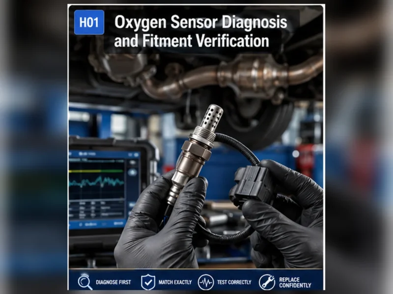
An oxygen sensor measures the oxygen remaining in exhaust gas and sends an electrical signal to the engine control module. The control module uses upstream sensor feedback to evaluate and adjust combustion, while downstream sensors are commonly used to monitor catalyst performance. The sensor reports evidence; it does not directly add fuel, repair a mixture problem, or prove which component has failed. Correct interpretation depends on whether the sensor is narrowband, wideband/A/F or titania, whether it is before or after the catalyst, and whether the engine has reached the required operating state. Before replacement, identify the exact bank and position, inspect the circuit and exhaust, and compare fuel trims and live response with vehicle service information.
The signal path: exhaust, sensor, ECU and fuel control
Combustion leaves a changing amount of oxygen in the exhaust. A sensor installed in the exhaust stream reacts to that oxygen and produces a voltage or current signal. The engine control module interprets the signal together with load, temperature, airflow, fuel-trim and other inputs. On a warm engine in closed-loop operation, the module can correct injector command to keep combustion near its intended target.
This is a feedback loop, not a standalone measurement system. An intake leak, low fuel pressure, injector problem, exhaust leak or wiring fault can change the sensor signal without the sensing element being the root cause.
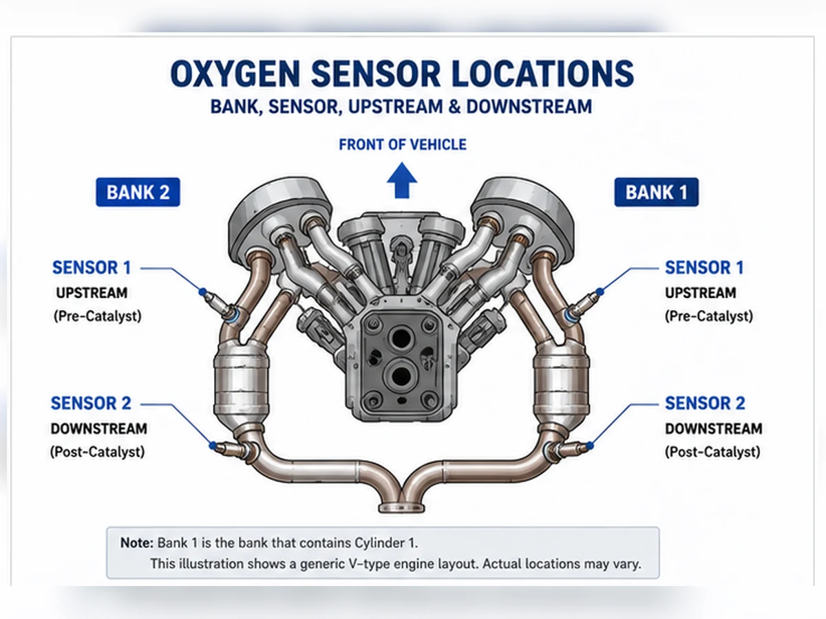
What upstream and downstream sensors do
| Position | Typical task | Diagnostic boundary |
|---|---|---|
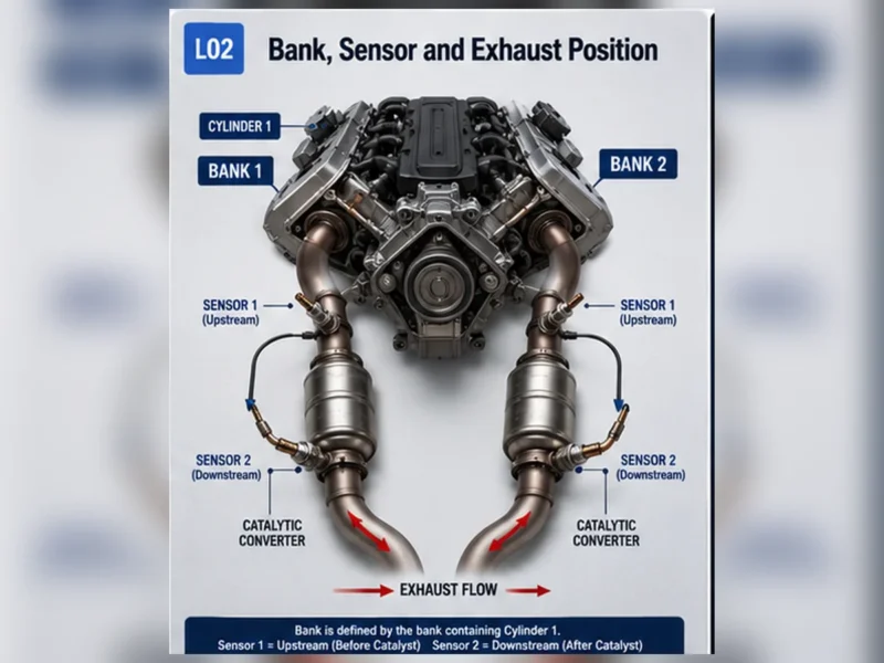
| Upstream / pre-catalyst / usually Sensor 1 | Provides mixture feedback used for fuel control. | A lean or rich indication can be caused by the engine, air/fuel system, wiring or an exhaust leak. |
| Downstream / post-catalyst / usually Sensor 2 | Helps the control module evaluate catalyst oxygen-storage performance. | A catalyst-efficiency code does not automatically prove that the rear sensor or catalyst must be replaced. |
“Usually” matters. Position naming must be confirmed from vehicle service information. Bank 1 is the bank containing cylinder 1, not a universal driver-side or passenger-side rule.
Why sensor technology changes the signal
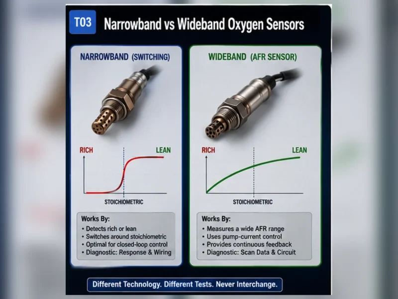
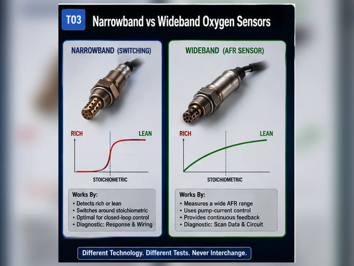
Narrowband zirconia sensors are commonly interpreted around a rich/lean switching point. Wideband or air-fuel-ratio sensors use a more complex control circuit and can report mixture deviation across a wider range. Titania designs operate differently again. A scan-tool graph that is normal for one technology can be misleading for another, so diagnosis requires the correct service specification.
What happens when the signal is wrong
A biased, slow, disconnected or unheated sensor can contribute to poor fuel control, increased emissions, drivability complaints or a warning light. However, the same symptoms can be produced by other systems. Before replacement, inspect the harness and connector, check heater power and ground when relevant, look for exhaust leaks, review fuel trims and compare live data with the manufacturer’s diagnostic procedure.
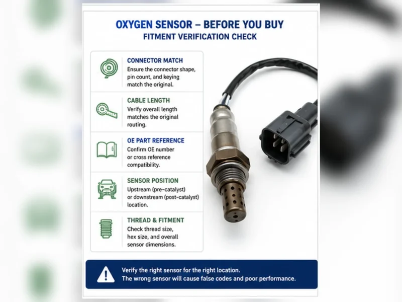
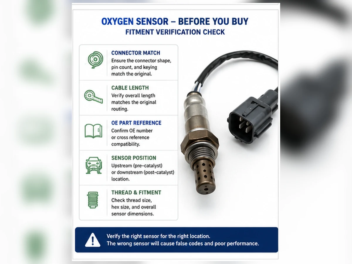
What to record before ordering
- OE number from the removed part or a verified catalog source
- Year, make, model, engine and market
- Bank and sensor position
- Connector keying, pin count and wire length
- Sensor technology and direct-fit or universal design
- Relevant diagnostic results, not only the trouble code
What is inside an oxygen sensor?
The visible threaded shell is only the mechanical interface. Inside, the sensing element operates at elevated temperature and is protected from direct exhaust impact by a shield. A heater helps the element reach and maintain its operating range. Electrical terminals carry the sensing and heater circuits through a heat-resistant cable to an application-specific connector. The exact construction varies by narrowband, titania and wideband design.
Sensing element and reference strategy
A zirconia narrowband element develops a signal related to the oxygen difference across the ceramic. It is useful around the rich/lean switching region but is not a laboratory exhaust-gas analyzer. A wideband sensor adds a pump-cell control strategy that enables a broader mixture measurement. The control module and sensor form a matched electrical system; a wideband part cannot be judged by the familiar narrowband voltage pattern.
Heater circuit
The heater shortens the time before useful feedback and helps maintain temperature at idle or low load. A heater code can result from an open element, high resistance, a blown fuse, damaged wiring, poor ground, connector resistance or a control-side fault. Measuring only the sensor resistance does not complete the circuit diagnosis.
Shield, thread, cable and connector
The shield controls gas exposure and protects the element. Thread and hex dimensions determine mechanical installation. Cable length, insulation, strain relief and clips keep the harness away from the exhaust and moving components. Connector shape alone is not enough: keying, pin assignment and electrical characteristics must match the application.
How the sensor’s role changes with operating state
| Operating state | What the control system may do | Diagnostic caution |
|---|---|---|
| Cold start | Use programmed fueling while the sensor and catalyst warm. | A cold signal should not be compared with warm closed-loop specifications. |
| Warm idle | Use feedback when enable conditions are met. | Exhaust leaks and low flow can strongly influence readings. |
| Steady cruise | Apply short- and long-term correction and run some monitors. | Load, speed and temperature must be stable for comparisons. |
| Acceleration or high load | Use strategy-specific enrichment or open-loop control. | A rich indication may be commanded rather than a fault. |
| Deceleration fuel cut | Reduce or stop injection under defined conditions. | High exhaust oxygen may be expected during the event. |
This is why a screenshot of one scan-tool value rarely answers whether the sensor works. The technician needs the commanded state, engine temperature, load, fuel trims, sensor technology and the manufacturer’s expected response under that test.
How to interpret oxygen-sensor data without guessing
Start with the data label and units
A scan tool may display voltage, current, lambda, equivalence ratio or a calculated value. Confirm that the data identifier is supported by the vehicle and corresponds to the physical sensor being tested. Generic scan-tool labels can simplify manufacturer-specific systems.
Compare response, not one number
For a narrowband sensor, the useful observation may be switching response under defined warm conditions. For a wideband sensor, the procedure may evaluate pump current or lambda response to a controlled change. Compare the result with fuel trims and commanded mixture. A sensor that reports lean while fuel trim adds fuel could be accurately exposing an air or fuel-delivery problem.
Use the downstream signal in context
The rear sensor is evaluated alongside the front sensor and catalyst operating conditions. Similar-looking waveforms can raise a catalyst-monitor concern, but exhaust leaks, misfire and sensor bias must be excluded. P0420 or P0430 is not a direct instruction to replace either sensor.
What common test tools can and cannot establish
| Tool or evidence | Useful for | Important limitation |
|---|---|---|
| Visual inspection | Finding melted wiring, loose connectors, impact damage and obvious exhaust leakage | Cannot prove internal response or calibration. |
| Scan tool | Reading codes, freeze frame, fuel trims, monitor status and supported sensor data | Labels and data rates vary; generic values may not represent the manufacturer test. |
| Digital multimeter | Checking power, ground, continuity and resistance where the procedure permits | May not capture fast signal behavior and can damage circuits if used incorrectly. |
| Oscilloscope | Observing waveform shape, response and intermittent circuit behavior | The waveform still needs known operating conditions and technology-specific interpretation. |
| Smoke or leak test | Locating intake or exhaust leaks that distort mixture evidence | Must be performed with suitable equipment and a safe, application-appropriate method. |
| Service information | Defining position, circuit, enable criteria, expected data and test sequence | Must match the exact vehicle, engine, market and calibration. |
No single tool replaces the evidence chain. A multimeter can show a heater circuit is open but not explain why a mixture code was stored. A scan graph can show a flat signal but not distinguish a dead sensor from a missing power supply, an unsupported data identifier or an engine that has not entered the required test state. Combine the tool result with the circuit diagram and operating conditions.
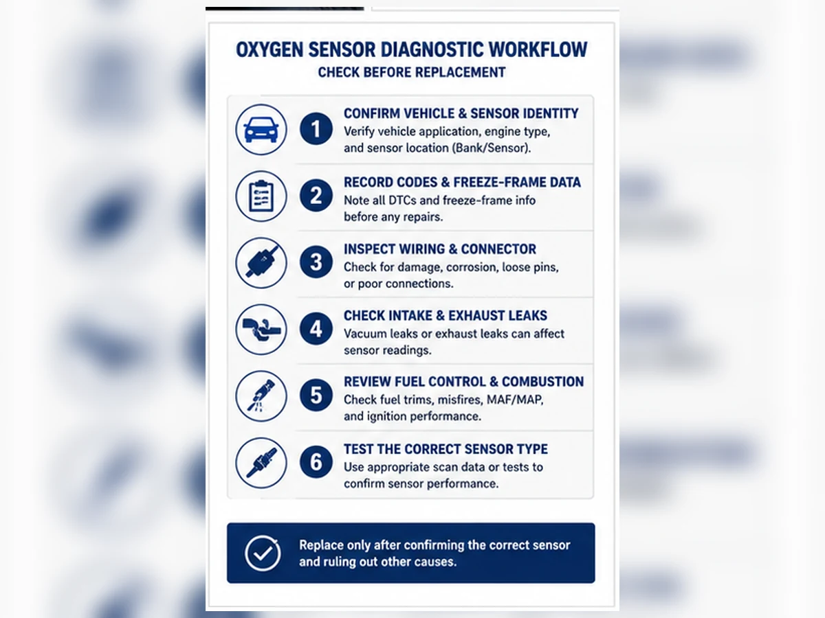
Sensor fault or system fault? Use a controlled change
A useful diagnostic test changes one known condition and observes whether the reported value responds in the expected direction and time. The exact method must come from service information; deliberately creating unsafe rich or lean conditions is not appropriate. The reasoning is what matters: if other data confirms the mixture changed and the sensor did not respond, suspicion moves toward the sensor or circuit. If the sensor responds but fuel trims remain abnormal, continue investigating the air, fuel, ignition or mechanical system.
Also check whether the fault follows a harness movement, temperature change or connector disturbance. Intermittent opens near the hot exhaust can appear only after expansion. Document the original routing before repair and restore every heat shield and clip. A correct sensor connected through a damaged harness cannot perform its function reliably.
Why oxygen sensors become slow, biased or damaged
| Mechanism | Possible evidence | Correct next step |
|---|---|---|
| Thermal aging | Slower response after long heat exposure | Verify response using the specified test before replacement. |
| Oil or coolant contamination | Deposits plus consumption or cooling-system symptoms | Correct the engine leak; a new sensor alone may fail again. |
| Silicone or chemical poisoning | Persistent bias or deposits linked to unsuitable sealant/fluids | Remove the contamination source and follow approved materials. |
| Impact or improper handling | Damaged shield, ceramic or cable | Replace the damaged part and correct installation practice. |
| Harness heat damage | Melted insulation, intermittent signal or heater code | Repair routing and circuit integrity, not only the sensor. |
| Exhaust leak | Outside air changes the reading near the sensor | Repair the leak before evaluating sensor response. |
Composite diagnostic scenario: when a lean signal is correct
Composite engineering scenario: a warm engine sets a lean code and the upstream sensor remains lean while fuel trim rises. Replacing the sensor would be tempting. A smoke test instead finds an intake leak downstream of the airflow measurement. After the leak is repaired, fuel trim returns toward the vehicle’s expected range and the sensor responds normally.
This scenario combines common diagnostic logic and does not represent a Sunhyings customer, vehicle or test result. Its purpose is to show the sensor’s actual function: it can be the messenger rather than the cause.
What an oxygen sensor cannot tell you by itself
- It cannot identify which injector, gasket or ignition component caused the exhaust condition.
- It cannot prove catalyst condition from a single stationary reading.
- It cannot establish vehicle fitment from thread or connector appearance.
- It cannot distinguish every contamination source without physical and system evidence.
- It cannot make an emissions bypass a legal or effective repair.
The correct next step depends on the user task. For diagnosis, follow the fault-code and live-data test path. For replacement, use the vehicle procedure and safe exhaust-system practices. For purchasing, build a complete OE/YMME/position record before comparing suppliers or prices.
Safety and compliance boundary after diagnosis
If testing supports removal, let the exhaust cool and use approved vehicle-lifting and support equipment. Route the harness away from heat, sharp edges and moving parts, and restore every clip and heat shield. Use the vehicle or sensor supplier’s torque and anti-seize instructions instead of a universal value. Do not cut a direct-fit harness; a universal splice-in design must be listed for the application and installed by its manufacturer’s procedure.
After repair, verify the circuit and sensor response under the required conditions and allow the applicable readiness monitor to complete. Clearing a code does not prove the repair. A spacer, simulator, sensor delete or software defeat cannot replace lawful diagnosis and may violate emissions regulations.
Function-to-action decision table
| User observation | What the sensor function suggests | Action before ordering |
|---|---|---|
| Lean code and positive fuel trim | The sensor may be reporting real excess oxygen. | Check intake/exhaust leaks, fuel delivery and airflow data. |
| Heater code | The element may not reach operating temperature as expected. | Test fuse, power, ground, control, connector and heater resistance. |
| Slow-response code | The signal did not change within monitor criteria. | Verify operating conditions, leaks, mixture control and sensor technology. |
| Catalyst-efficiency code | The monitor detected an upstream/downstream relationship concern. | Check engine, exhaust, sensor and catalyst evidence together. |
| Correct diagnosis supports replacement | The sensor or integrated harness cannot meet its required function. | Verify OE reference, exact position, technology and physical interface. |
Prepare a fitment or sourcing request
Send the OE number, year/make/model, engine or VIN details, market and emissions package, exact bank/sensor position, connector and old-part photos, quantity and any packaging or approval requirements. Sunhyings will review the supplied data for capability and sourcing feasibility; fitment is not confirmed until application evidence is matched.
Frequently asked questions
Does an oxygen sensor control fuel directly?
No. It sends a signal to the engine control module, which decides whether and how to adjust injector command using multiple inputs.
Does every oxygen sensor perform the same job?
No. Upstream sensors primarily support mixture feedback, while downstream sensors commonly support catalyst monitoring. Technology and vehicle strategy also differ.
Can a good oxygen sensor report a lean condition?
Yes. Intake leaks, low fuel delivery, exhaust leaks and other faults can create a genuinely lean exhaust signal.
Is an O2 sensor the same as an oxygen sensor?
Yes. O2 sensor is the common shortened name, although air-fuel-ratio and wideband sensors may use different signal strategies.
Does P0420 prove the oxygen sensor failed?
No. P0420 concerns catalyst-system efficiency. Sensor data is part of diagnosis, but the code does not identify a failed oxygen sensor by itself.
What information is needed to select a replacement?
Verify the OE reference, vehicle and engine, market or emissions package, exact bank and position, connector, wire length and sensor technology.