Oxygen Sensor Technical Guide
Most modern vehicles use multiple oxygen sensors, but the exact count depends on engine banks, exhaust layout, catalysts, model year and emissions configuration.

Quick answer
A modern car commonly has two or four oxygen sensors, but there is no count that applies to every vehicle. A single-bank engine often has at least one sensor before and one after the catalyst. A V engine with two monitored banks often has an upstream and downstream sensor for each bank. Additional catalysts, split exhaust systems and emissions variants can change the number.
Common layouts, without assuming exact fitment
| Generic layout | Common count | Reason to verify |
|---|---|---|
| Single bank, one monitored catalyst | Often 2 | Some older or special systems use a different arrangement. |
| Two banks, one catalyst path per bank | Often 4 | Shared or additional catalysts can change the count. |
| Older pre-OBD-II application | May use 1 or another layout | Model year and market rules vary. |
| Complex multi-catalyst exhaust | Can exceed 4 | Service diagrams and VIN-based catalogs are required. |
Engine cylinder count alone is not enough. A four-cylinder can have more than two sensors, and a V6 or V8 does not automatically have exactly four. Exhaust routing and monitoring strategy determine the installed positions.
Bank 1, Bank 2, Sensor 1 and Sensor 2
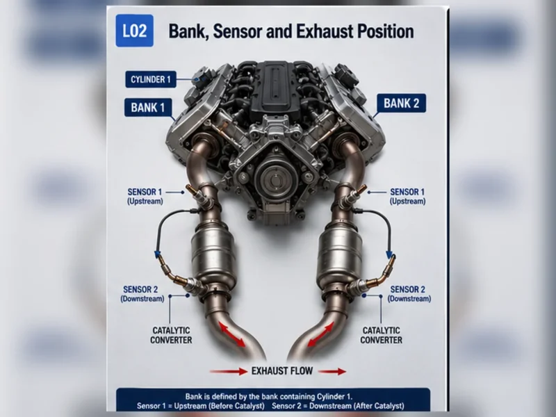
Bank 1 is the side containing cylinder 1; Bank 2 is the other bank on engines with two banks. Sensor 1 is commonly before the catalyst and Sensor 2 after it for that bank. Driver-side and passenger-side shortcuts are unreliable because engine orientation differs.
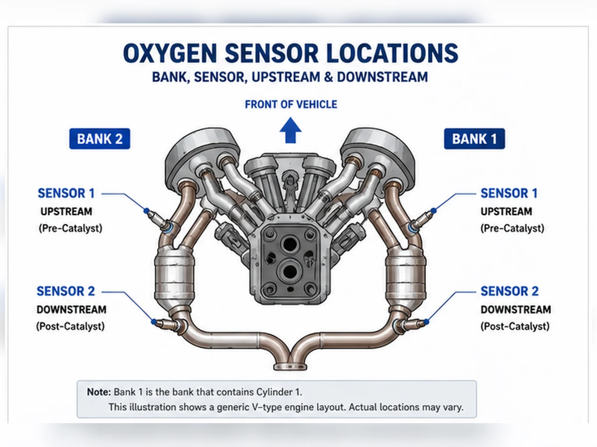
Three reliable ways to find the exact count
- Use the VIN and engine information in current manufacturer service information.
- Review the emissions label and an application catalog that distinguishes market and emissions package.
- Inspect the complete exhaust system only when the vehicle is cool and safely supported, tracing every connector and sensor position.
Why one code does not reveal the total count
A code such as Bank 1 Sensor 2 identifies one monitored circuit, not every sensor installed on the vehicle. Scan tools may also display unsupported data identifiers. Confirm the engine and exhaust diagram before concluding that a displayed position physically exists.
Should all sensors be replaced together?
Not automatically. Diagnose the identified fault, inspect common power or ground circuits, and consider age and access only as planning factors. Replacing functioning sensors adds cost and can introduce connector, thread or routing problems without fixing the root cause.
Count exhaust-monitoring positions, not cylinders
Sensor count follows the exhaust and catalyst architecture. Cylinder count can suggest whether an engine has one or two banks, but it does not show whether banks merge before a catalyst, whether each bank has separate catalysts or whether additional monitored catalysts are installed. Start with an exhaust diagram, not a rule such as “four-cylinder equals two sensors.”
| Architecture question | Why it changes count | Evidence source |
|---|---|---|
| How many engine banks? | Each bank may need an upstream feedback position | Engine cylinder numbering/service data |
| Where do exhaust paths merge? | Shared paths can change sensor and catalyst arrangement | Exhaust diagram |
| How many monitored catalysts? | Each monitored path may have downstream sensing | Emissions/service information |
| Are there regional variants? | Federal, California or other packages may differ | Emissions label and VIN-based catalog |
Single-bank layouts
One upstream and one downstream position
A single-bank engine with one monitored catalyst commonly has two sensors: Sensor 1 before the catalyst and Sensor 2 after it. This is a common pattern, not a universal count. Older systems, close-coupled plus underfloor catalysts or market-specific configurations can differ.
Additional catalyst stages
An engine can have more than one catalyst stage or additional sensing positions. The label “Sensor 3” or manufacturer-specific naming requires the exact diagram. Do not assume that every sensor after the first catalyst is interchangeable.
Two-bank layouts
Separate catalyst paths
A V engine with one upstream and one downstream sensor per bank commonly has four. Bank 1 is the side containing cylinder 1, not a universal driver or passenger side. Each circuit must be matched to its physical connector.
Merged or complex exhaust paths
Banks can merge, catalysts can be shared or additional catalysts can be monitored. As a result, a V6 or V8 may not have exactly four sensors. Model year, engine and emissions configuration control the answer.
| Generic pattern | Possible positions | Do not assume |
|---|---|---|
| Single bank / one catalyst | B1S1 and B1S2 | Every inline engine has only two |
| Two banks / separate catalysts | B1S1, B1S2, B2S1, B2S2 | Every V engine has exactly four |
| Multiple catalyst stages | Additional manufacturer-defined positions | Sensor 3 naming is identical across brands |
| Older/market-specific system | Fewer or different positions | Modern OBD layout applies retroactively |
Use VIN and build data correctly
The VIN helps identify vehicle, engine and configuration when decoded by current manufacturer or catalog data. It is not a self-contained sensor-count answer. Production date or VIN breakpoint may separate exhaust variants. Record the sales market and emissions label because a catalog may otherwise return the wrong regional arrangement.
Why codes and scan-tool lists can mislead
A code naming Bank 1 Sensor 2 proves that the control system monitors that named circuit; it does not list every installed sensor. Generic scan tools may display unsupported PIDs or labels for positions not used by the vehicle. Confirm data activity and service documentation before turning the menu into a physical count.
| Evidence | Useful for | Limitation |
|---|---|---|
| DTC description | Identifying one circuit/monitor path | Does not enumerate all sensors |
| Scan-tool PID list | Viewing supported operating data | Generic list can include unsupported labels |
| Parts catalog | Finding candidates by application | May show alternatives or supersessions, not quantity |
| Service exhaust diagram | Mapping every physical position | Must match engine, market and build |
Physical inspection without creating a safety risk
Inspect only when the exhaust is cool and the vehicle is supported with approved equipment. Trace each sensor body to its connector and note whether it is before or after a catalyst. Heat shields, undertrays and close-coupled catalysts can hide positions. Do not crawl under a vehicle supported only by a jack, pull on wiring or confuse exhaust-temperature sensors with oxygen sensors.
Count is not enough to order parts
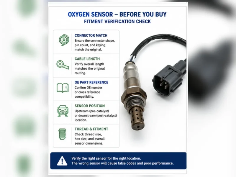
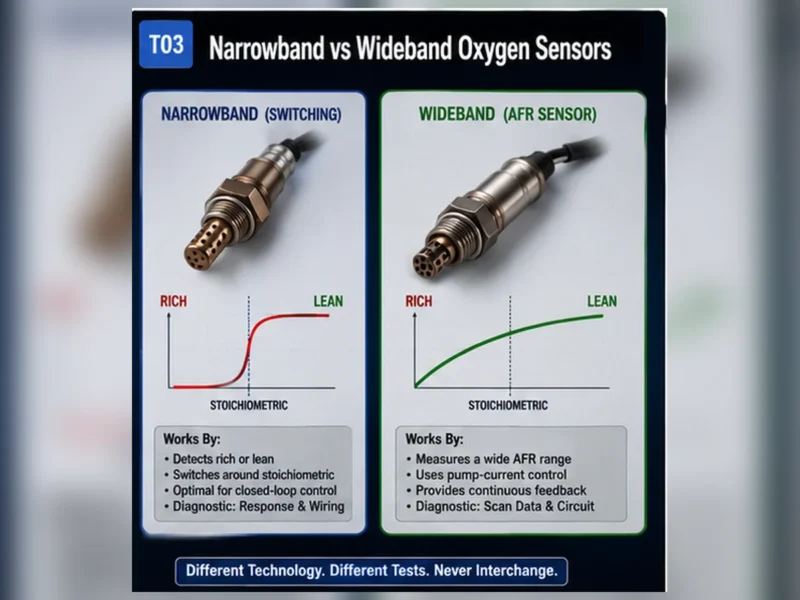
Even when the vehicle has four sensors, the four parts may not be identical. Upstream positions can use wideband/A/F designs while downstream positions use narrowband designs; Bank 1 and Bank 2 leads or clips can differ. Verify the OE reference, exact position, technology, connector and cable for each replacement.
Composite scenario: a catalog result is mistaken for quantity
Composite parts scenario: a catalog returns three part-number options for one model. The buyer assumes the vehicle has three sensors. The service diagram shows four physical positions, with one part number used in two positions and different numbers for the others. This composite example shows why catalog-result count and installed quantity are separate questions.
Create a position inventory
| Record field | Example format | Purpose |
|---|---|---|
| Position | Bank 1 Sensor 1 | Separates physical circuits |
| Catalyst relation | Pre-catalyst | Confirms upstream/downstream role |
| OE number | Read or verified catalog value | Anchors part selection |
| Connector/lead | Photo, pins, length and clips | Prevents interface mismatch |
| Diagnostic status | Tested / not tested | Avoids replacing all sensors by count alone |
Replace only the position supported by diagnosis unless the vehicle procedure or a documented repair plan justifies more work. Age and shared access can inform planning, but they do not prove that every sensor has failed.
Verify the inventory after repair
When a sensor is replaced, update the position inventory with the installed part number, lot or date code, connector/routing photos and diagnostic result. Confirm that every retained connector is locked and every cable remains clear of hot or moving parts. Work near one sensor can disturb an adjacent harness, especially where bank connectors share clips or a heat shield.
Use scan data to confirm the repaired physical position, not to recount the system from scratch. Observe the named circuit under valid conditions and complete the applicable monitor procedure. If a different position sets a code afterward, diagnose it independently instead of concluding that all sensors should have been replaced together.
Quantity for distributor orders
Installed quantity per vehicle and purchase quantity are different fields. A distributor forecast must account for application population, position-specific demand, returns and packaging, not multiply one generic sensor by the count. Approve each part number’s coverage and position before building a kit or paired offer.
Kit descriptions should list every included position and part number and state the engine, market and emissions scope. “Complete four-sensor kit” is unsafe when the count or interchangeability has not been confirmed. A missing or extra sensor in a kit is a catalog-control problem, not an installation workaround.
Prepare a fitment or sourcing request
Send the OE number, year/make/model, engine or VIN details, market and emissions package, exact bank/sensor position, connector and old-part photos, quantity and any packaging or approval requirements. Sunhyings will review the supplied data for capability and sourcing feasibility; fitment is not confirmed until application evidence is matched.
Frequently asked questions
Do all cars have two oxygen sensors?
No. Two is common for a single-bank system with one monitored catalyst, but vehicle layouts vary.
Does a V6 always have four O2 sensors?
No. Four is common for two-bank systems, but shared or additional catalysts and emissions variants can change the count.
Can the VIN tell me how many sensors are fitted?
The VIN helps identify the engine and configuration when used with current service or catalog data; the VIN string alone must be decoded correctly.
Is Bank 1 always the driver side?
No. Bank 1 is the bank containing cylinder 1, and its physical side varies by engine and installation.
Should I replace every sensor if one fails?
Not by default. Diagnose the affected circuit and replace only parts supported by evidence and service guidance.