Phone / WhatsApp :+86 15868721920

Adresse :Binhai Industrial Park, Longwan District, Wenzhou

How Many Oxygen Sensors Does a Car Have?

Most modern vehicles use multiple oxygen sensors, but the exact count depends on engine banks, exhaust layout, catalysts, model year and emissions configuration.

Oxygen Sensor Technical Guide

Most modern vehicles use multiple oxygen sensors, but the exact count depends on engine banks, exhaust layout, catalysts, model year and emissions configuration.

Method for determining oxygen sensor count from engine banks catalysts and exhaust paths decision checkpoints
Sensor count comes from the exact exhaust architecture, not cylinder count or a generic model rule. The checkpoints summarize the evidence to confirm before the next decision.

Quick answer

A modern car commonly has two or four oxygen sensors, but there is no count that applies to every vehicle. A single-bank engine often has at least one sensor before and one after the catalyst. A V engine with two monitored banks often has an upstream and downstream sensor for each bank. Additional catalysts, split exhaust systems and emissions variants can change the number.

Common layouts, without assuming exact fitment

Generic layoutCommon countReason to verify
Single bank, one monitored catalystOften 2Some older or special systems use a different arrangement.
Two banks, one catalyst path per bankOften 4Shared or additional catalysts can change the count.
Older pre-OBD-II applicationMay use 1 or another layoutModel year and market rules vary.
Complex multi-catalyst exhaustCan exceed 4Service diagrams and VIN-based catalogs are required.

Engine cylinder count alone is not enough. A four-cylinder can have more than two sensors, and a V6 or V8 does not automatically have exactly four. Exhaust routing and monitoring strategy determine the installed positions.

Bank 1, Bank 2, Sensor 1 and Sensor 2

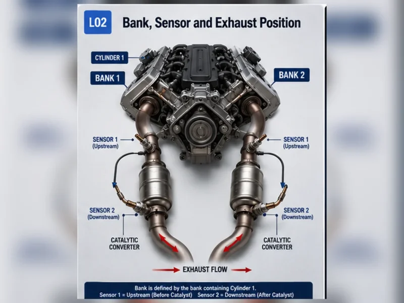
Bank 1 is the side containing cylinder 1; Bank 2 is the other bank on engines with two banks. Sensor 1 is commonly before the catalyst and Sensor 2 after it for that bank. Driver-side and passenger-side shortcuts are unreliable because engine orientation differs.
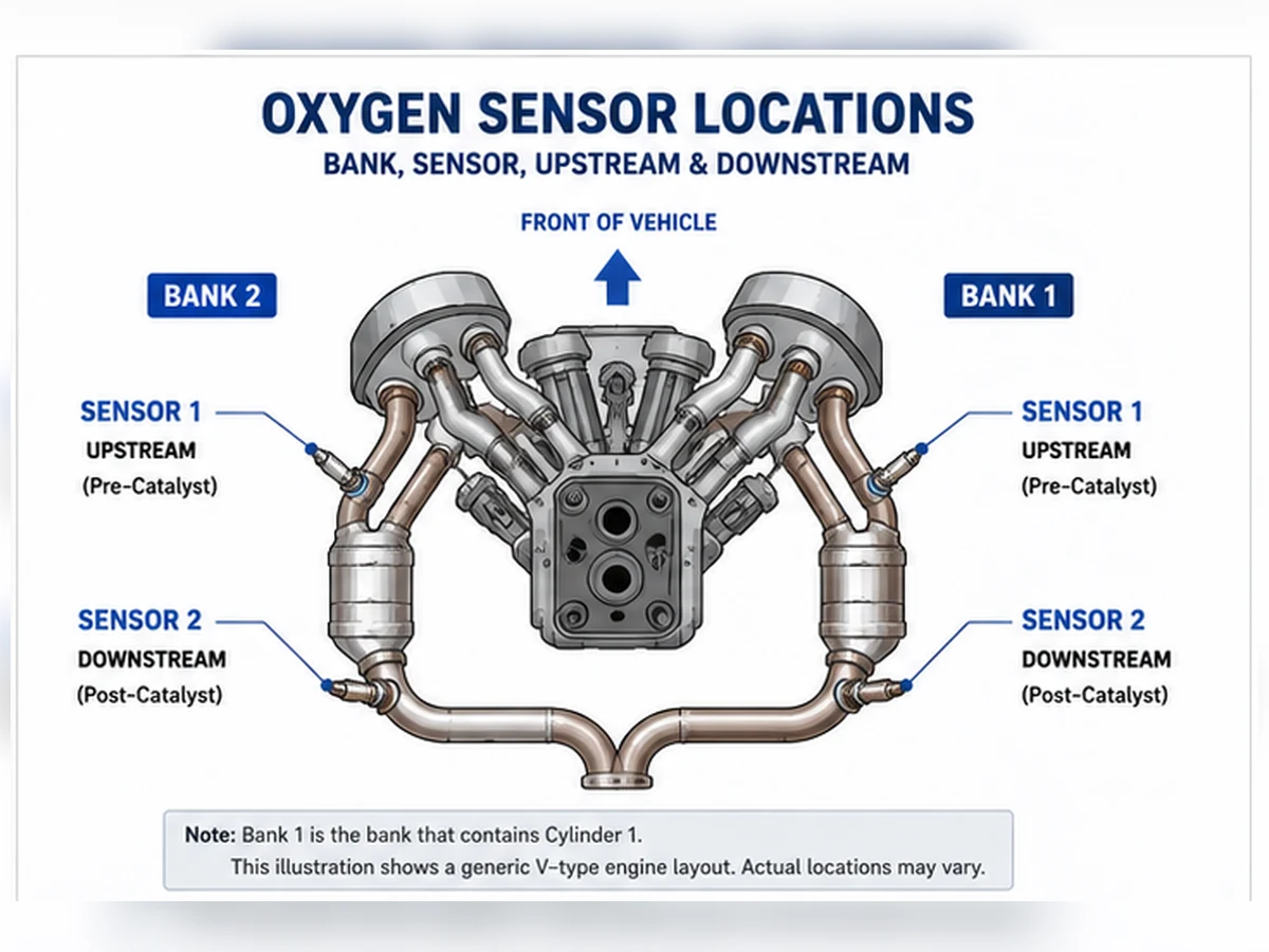
Generic Bank 1 Bank 2 Sensor 1 Sensor 2 oxygen sensor layout
A generic four-sensor layout. It is an identification aid, not a vehicle-specific fitment diagram.

Three reliable ways to find the exact count

  1. Use the VIN and engine information in current manufacturer service information.
  2. Review the emissions label and an application catalog that distinguishes market and emissions package.
  3. Inspect the complete exhaust system only when the vehicle is cool and safely supported, tracing every connector and sensor position.

Why one code does not reveal the total count

A code such as Bank 1 Sensor 2 identifies one monitored circuit, not every sensor installed on the vehicle. Scan tools may also display unsupported data identifiers. Confirm the engine and exhaust diagram before concluding that a displayed position physically exists.

Should all sensors be replaced together?

Not automatically. Diagnose the identified fault, inspect common power or ground circuits, and consider age and access only as planning factors. Replacing functioning sensors adds cost and can introduce connector, thread or routing problems without fixing the root cause.

Count exhaust-monitoring positions, not cylinders

Sensor count follows the exhaust and catalyst architecture. Cylinder count can suggest whether an engine has one or two banks, but it does not show whether banks merge before a catalyst, whether each bank has separate catalysts or whether additional monitored catalysts are installed. Start with an exhaust diagram, not a rule such as “four-cylinder equals two sensors.”

Architecture questionWhy it changes countEvidence source
How many engine banks?Each bank may need an upstream feedback positionEngine cylinder numbering/service data
Where do exhaust paths merge?Shared paths can change sensor and catalyst arrangementExhaust diagram
How many monitored catalysts?Each monitored path may have downstream sensingEmissions/service information
Are there regional variants?Federal, California or other packages may differEmissions label and VIN-based catalog

Single-bank layouts

One upstream and one downstream position

A single-bank engine with one monitored catalyst commonly has two sensors: Sensor 1 before the catalyst and Sensor 2 after it. This is a common pattern, not a universal count. Older systems, close-coupled plus underfloor catalysts or market-specific configurations can differ.

Additional catalyst stages

An engine can have more than one catalyst stage or additional sensing positions. The label “Sensor 3” or manufacturer-specific naming requires the exact diagram. Do not assume that every sensor after the first catalyst is interchangeable.

Two-bank layouts

Separate catalyst paths

A V engine with one upstream and one downstream sensor per bank commonly has four. Bank 1 is the side containing cylinder 1, not a universal driver or passenger side. Each circuit must be matched to its physical connector.

Merged or complex exhaust paths

Banks can merge, catalysts can be shared or additional catalysts can be monitored. As a result, a V6 or V8 may not have exactly four sensors. Model year, engine and emissions configuration control the answer.

Generic patternPossible positionsDo not assume
Single bank / one catalystB1S1 and B1S2Every inline engine has only two
Two banks / separate catalystsB1S1, B1S2, B2S1, B2S2Every V engine has exactly four
Multiple catalyst stagesAdditional manufacturer-defined positionsSensor 3 naming is identical across brands
Older/market-specific systemFewer or different positionsModern OBD layout applies retroactively

Use VIN and build data correctly

The VIN helps identify vehicle, engine and configuration when decoded by current manufacturer or catalog data. It is not a self-contained sensor-count answer. Production date or VIN breakpoint may separate exhaust variants. Record the sales market and emissions label because a catalog may otherwise return the wrong regional arrangement.

Why codes and scan-tool lists can mislead

A code naming Bank 1 Sensor 2 proves that the control system monitors that named circuit; it does not list every installed sensor. Generic scan tools may display unsupported PIDs or labels for positions not used by the vehicle. Confirm data activity and service documentation before turning the menu into a physical count.

EvidenceUseful forLimitation
DTC descriptionIdentifying one circuit/monitor pathDoes not enumerate all sensors
Scan-tool PID listViewing supported operating dataGeneric list can include unsupported labels
Parts catalogFinding candidates by applicationMay show alternatives or supersessions, not quantity
Service exhaust diagramMapping every physical positionMust match engine, market and build

Physical inspection without creating a safety risk

Inspect only when the exhaust is cool and the vehicle is supported with approved equipment. Trace each sensor body to its connector and note whether it is before or after a catalyst. Heat shields, undertrays and close-coupled catalysts can hide positions. Do not crawl under a vehicle supported only by a jack, pull on wiring or confuse exhaust-temperature sensors with oxygen sensors.

Count is not enough to order parts

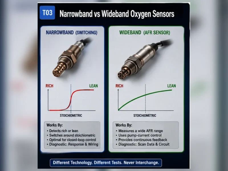
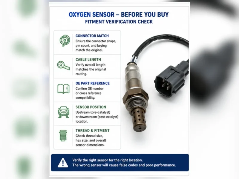
Even when the vehicle has four sensors, the four parts may not be identical. Upstream positions can use wideband/A/F designs while downstream positions use narrowband designs; Bank 1 and Bank 2 leads or clips can differ. Verify the OE reference, exact position, technology, connector and cable for each replacement.

Composite scenario: a catalog result is mistaken for quantity

Composite parts scenario: a catalog returns three part-number options for one model. The buyer assumes the vehicle has three sensors. The service diagram shows four physical positions, with one part number used in two positions and different numbers for the others. This composite example shows why catalog-result count and installed quantity are separate questions.

Create a position inventory

Record fieldExample formatPurpose
PositionBank 1 Sensor 1Separates physical circuits
Catalyst relationPre-catalystConfirms upstream/downstream role
OE numberRead or verified catalog valueAnchors part selection
Connector/leadPhoto, pins, length and clipsPrevents interface mismatch
Diagnostic statusTested / not testedAvoids replacing all sensors by count alone

Replace only the position supported by diagnosis unless the vehicle procedure or a documented repair plan justifies more work. Age and shared access can inform planning, but they do not prove that every sensor has failed.

Verify the inventory after repair

When a sensor is replaced, update the position inventory with the installed part number, lot or date code, connector/routing photos and diagnostic result. Confirm that every retained connector is locked and every cable remains clear of hot or moving parts. Work near one sensor can disturb an adjacent harness, especially where bank connectors share clips or a heat shield.

Use scan data to confirm the repaired physical position, not to recount the system from scratch. Observe the named circuit under valid conditions and complete the applicable monitor procedure. If a different position sets a code afterward, diagnose it independently instead of concluding that all sensors should have been replaced together.

Quantity for distributor orders

Installed quantity per vehicle and purchase quantity are different fields. A distributor forecast must account for application population, position-specific demand, returns and packaging, not multiply one generic sensor by the count. Approve each part number’s coverage and position before building a kit or paired offer.

Kit descriptions should list every included position and part number and state the engine, market and emissions scope. “Complete four-sensor kit” is unsafe when the count or interchangeability has not been confirmed. A missing or extra sensor in a kit is a catalog-control problem, not an installation workaround.

There is no universal sensor count by cylinder count

A four-cylinder engine can have two sensors in a simple single-catalyst layout, but additional catalyst stages or market-specific emissions systems can change the count. A V engine can have separate upstream and downstream sensors for each bank, yet merged exhaust or different monitor architecture can change that pattern. Cylinder count is an orientation clue, not a purchase quantity.

Vehicle descriptionCommon assumptionWhy verification is still required
Inline four-cylinderOne upstream and one downstreamMay have close-coupled plus underfloor catalyst or extra sensor
V6/V8 with two banksFour sensorsExhaust paths can merge; catalyst stages and market variants differ
Turbocharged engineTwo sensors near turbo/catalystPackaging, wideband feedback and aftertreatment layout vary
Hybrid vehicleSame count as non-hybrid engineEngine family, calibration and exhaust system may differ
Same model/yearOne count for all trimsEngine, drivetrain, emissions market and build breakpoint can differ

Six-step method to determine the actual count

  1. Identify the exact vehicle. Record VIN, year, make, model, engine and sales/emissions market.
  2. Find the engine bank layout. Determine whether there is one bank or multiple banks and locate cylinder 1.
  3. Trace each exhaust path. Identify manifolds, merge points, catalyst stages and outlet paths.
  4. Locate every sensor position. Use the component-location diagram and wiring connector list, not visibility alone.
  5. Reconcile scan/catalog data. Match Bank/Sensor labels and OE/application records to physical locations.
  6. Count only verified positions. Record technology and part identity for each; do not assume one SKU fits all.
SourceWhat it confirmsLimitation
OEM service component diagramPhysical positions and exhaust relationshipsMust match exact engine/market
Wiring diagramSensor circuits, connectors and shared suppliesMay require separate location view
Parts catalogCandidate OE/application mappingsCan contain supersessions or data conflicts
VIN/build/emissions labelVehicle configurationDoes not alone draw exhaust layout
Physical inspectionInstalled bungs, sensors, routes and prior repairsInstalled system may have been modified or repaired incorrectly
Scan data/DTC listController-recognized bank/sensor channelsNo-code sensor can still exist; labels need physical mapping

Count sensors by monitored exhaust path

Generic layoutPossible sensor rolesCounting caution
One bank, one catalystSensor 1 before and Sensor 2 after catalystConfirm no additional downstream stage
Two banks, two catalystsB1S1/B1S2 and B2S1/B2S2Do not assign sides without cylinder numbering
Two banks merge before one catalystBank-specific upstream plus shared downstreamBank count does not equal downstream count
Close-coupled and underfloor catalystsSensor before/between/after stagesSensor 3 or manufacturer-specific naming may appear
Dual exhaust after shared engine pathMonitoring depends on catalyst architectureTailpipe count does not define sensor count
Modified exhaustInstalled count may differ from designed systemRestore legal configuration; do not normalize deletes/spacers

Bank and Sensor names are identifiers, not a counting formula

Bank 1 contains cylinder 1. Sensor 1 is usually before the monitored catalyst; Sensor 2 is usually after it. Additional sensors may be named Sensor 3 or represented with manufacturer-specific terminology. A list containing B1S1 and B1S2 does not prove there is a Bank 2, and a V engine does not prove both banks use separate downstream sensors.

IdentifierTypical meaningQuestion still open
B1S1Pre-catalyst sensor on cylinder 1 bankTechnology, connector and exact physical route
B1S2Post-catalyst sensor on Bank 1 pathWhich catalyst stage and part identity
B2S1Pre-catalyst sensor on opposite bankPhysical side and interchangeability with B1S1
B2S2Post-catalyst sensor on Bank 2 pathWhether exhaust remains bank-separated
Sensor 3Additional downstream/intermediate positionExact manufacturer layout and role

More than one sensor does not mean more than one identical part

Direct-fit oxygen sensor with a long protected cable, keyed connector and routing clips
A correct sensing element is not enough: lead length, connector keying and routing provisions must match the exact exhaust position.

Upstream positions may use wideband/A/F technology while downstream positions use narrowband. Bank 1 and Bank 2 parts can differ in lead length, connector keying or clips even when sensing strategy is similar. A four-sensor vehicle can therefore require several part numbers. Verify each position separately.

ComparisonEvidence required for interchangeability
Technology/electricalSame specified sensing strategy, heater and circuit
Application positionCurrent catalog explicitly approves both positions
Connector/pinsKeying, terminals and pin assignment agree
Lead/routeLength, insulation, clips and strain relief suit both routes
Thread/shieldMechanical and exposure geometry match specification
ValidationPart-level evidence covers claimed application positions

Why count matters during diagnosis

A code naming Bank 2 Sensor 1 is useful only if the physical layout and connector are mapped correctly. Shared heater supplies can affect multiple sensors. Crossed connectors after repair can make scan data appear to belong to the wrong bank. Counting and mapping the complete system prevents the technician from testing the first visible sensor.

Diagnostic patternCount/map questionNext check
Two heater codesDo sensors share power, fuse or ground/control?Loaded common-circuit test
Opposite-bank responseAre connectors crossed or labels mis-mapped?Wiring/location reconciliation
P0420/P0430Which sensors monitor the named catalyst path?Complete bank engine/exhaust/catalyst diagnosis
One missing scan parameterIs sensor/channel supported and enabled?Service data and tool capability
Repeated wrong-part returnWas quantity used instead of position identity?Audit application rows and order fields

Composite case: a two-bank engine has three sensors

Composite diagnostic scenario: a technician expects four sensors because the engine has two banks. The exact exhaust diagram shows two bank-specific upstream sensors and one downstream sensor after the exhaust merges. The order is changed from a guessed B2S2 to the verified shared post-catalyst position.

This is a generic composite pattern, not a universal three-sensor rule and not a Sunhyings customer case.

Composite parts case: model-level catalog misses an additional sensor

Composite parts scenario: a model/year search returns two sensors, but the vehicle emissions configuration uses an additional catalyst-stage sensor. VIN/build and service data reveal the extra position and a different connector. The team splits the application row rather than shipping a two-sensor “kit.”

The case shows why model/year and cylinder count cannot control quantity. It is composite and contains no verified make/model claim.

Purchase record when more than one sensor is needed

PositionRecord separately
Vehicle applicationVIN/YMME, engine, market/emissions and build breakpoint
LocationBank, Sensor number and catalyst-relative position
Part identityOE candidate, supplier part and revision
TechnologyNarrowband, titania or wideband/A/F plus electrical requirements
InterfaceConnector, pins, lead, clips, thread and shield
ReasonDiagnostic evidence for replacing that position

Do not replace every sensor solely because one code exists or one sensor failed. Diagnose and approve each position. Sunhyings can review a position-by-position part list for sourcing feasibility; exact fitment, stock and commercial terms require confirmation.

Never reduce the count by defeating the system

A missing sensor, simulator, spacer, delete or software-suppressed monitor does not establish the correct designed count. Use service information to restore the legal configuration. “Off-road use” is not a universal exemption, and bypass instructions are outside responsible diagnosis and procurement.

Physical inspection checklist for confirming the count

Inspect only with the exhaust cool and the vehicle supported at approved points when underbody access is required. Use lighting and a camera or mirror rather than placing hands near an uncertain hot surface. Count sensor bodies and bungs, then follow each lead to its connector so an unused bung, temperature sensor or other exhaust device is not misidentified.

Inspection pointWhat to captureWhy
Manifold outletsEach bank/path and pre-catalyst sensorEstablishes upstream count
Catalyst stagesInlet/outlet and sensor relationshipSeparates Sensor 2 from additional positions
Merge/split pointsWhere bank-specific exhaust becomes sharedExplains shared downstream count
Connectors and clipsLead destination and branch identityConfirms physical-to-electrical mapping
Unused bungs/modificationsCaps, welds, spacers or missing devicesMay indicate prior exhaust change
Labels/part marksReadable number with position contextSupports separate part identity

Do not infer that every threaded exhaust device is an oxygen sensor. Exhaust-temperature and NOx sensors can have different functions and circuits. Verify component identity from service information and connector/wiring data.

Why “complete sensor kits” need position-by-position evidence

A kit advertised for a vehicle can be convenient only when it lists every included part, exact position and controlled application coverage. A quantity of two or four is not a technical specification. One incorrect sensor in a kit can create a forced connector, wrong lead route or unnecessary replacement even if the other parts fit.

Kit fieldRequired contentReject or hold condition
ApplicationYMME, engine, market/emissions and breakpointModel/year only
Position mapEvery Bank/Sensor and catalyst relationship“Front and rear set” without bank detail
Part listUnique SKU/revision for each positionLoose unlabeled sensors
TechnologyPart-specific narrowband/wideband/titania dataAll sensors treated as one type
InterfaceConnector, lead, clips, thread and shield by positionInstaller expected to adapt
Reason for replacementDiagnostic basis for each changed positionReplace all solely because one code exists

Decide how many sensors to replace, not only how many exist

The vehicle may contain several sensors while evidence supports replacing only one. Replace additional sensors only when their own condition, access strategy or a documented service recommendation justifies it. Do not claim that all sensors have the same life or must be changed as a set. When shared access could affect labor, disclose the trade-off without turning convenience into a diagnosis.

DecisionEvidenceBoundary
Replace one named sensorPosition-specific failure and exact fitmentVerify other shared circuits/root causes
Replace multiple sensorsIndependent failures or supported repair scopeNo universal paired-replacement rule
Repair harness/shared supplyCommon circuit fault affects several sensorsNew sensors cannot repair vehicle power/control
Correct engine/exhaust conditionSensors report a real shared conditionDo not replace responsive sensors
Continue diagnosisCount/position or test evidence conflictsDo not order to test the hypothesis

Fleet and distributor control for vehicles with several positions

Store one row per vehicle configuration, sensor position and approved part. Preserve source, revision and supersession history. A catalog architecture that stores only vehicle plus quantity cannot distinguish a wrong bank, lead or technology and cannot explain which row caused a return.

Data fieldPurpose
Vehicle/configuration keySeparates engine, emissions market and breakpoint
Position keyDefines Bank/Sensor and catalyst stage
Approved part/revisionPrevents family-level substitution
Source/revisionSupports audits and corrections
Interface/technologyChecks physical and electrical consistency
StatusApproved, blocked, superseded or under review

When an application correction changes the count, review published content, open orders, labels, kits and inventory together. Fixing only the web listing leaves warehouse and customer-service errors active.

Return analysis when the claimed count or kit is wrong

  • Preserve order, catalog revision, labels, part and lot/date.
  • Capture exact VIN/YMME, engine and emissions configuration.
  • Provide exhaust-layout and connector-route photographs.
  • List which positions installed, conflicted or were not present.
  • Separate catalog, packing, picking, product and vehicle-modification causes.
  • Block affected rows until the evidence conflict is resolved.

A distributor should not close the case by refund alone. Correct the source data and review whether other customers or inventory are affected. A buyer should not modify the harness or install a spacer to accommodate an incorrect kit because that destroys evidence and can compromise emissions compliance.

When sources disagree on the sensor count

Place the application in a blocked state and identify the exact configuration each source covers. Check VIN/build data, engine code, emissions label, catalyst layout, service-document revision and installed-system history. A physical count can reveal what is present, but it may reflect a prior modified or incorrect exhaust; the legal designed configuration remains the target.

ConflictResolution evidence
Catalog says two, service diagram shows threeConfirm engine/emissions applicability and catalog revision
Vehicle has fewer than designedInspect modification history and restore compliant configuration
Two diagrams use different Sensor numbersUse exact document/calibration and catalyst relationship
Scan tool lists a channel with no visible sensorCheck tool support, hidden location and wiring diagram
OE and aftermarket quantity differReview supersession, kit composition and each position row

Record the final count, source and date. Do not publish the number as universal for a model family. The correct answer belongs to the exact vehicle/engine/emissions configuration and exhaust design.

Count, position and part number are separate fields

The number tells how many devices exist; position tells where each serves; part number tells what fits that position. Keep all three in the repair and purchasing record. Converting one field into another is the main source of oversimplified answers.

If the count is needed only to buy one replacement, do not order the full quantity. Identify and diagnose the named position, then select its verified part. Count supports system understanding; it is not a blanket replacement recommendation.

Prepare a fitment or sourcing request

Send the OE number, year/make/model, engine or VIN details, market and emissions package, exact bank/sensor position, connector and old-part photos, quantity and any packaging or approval requirements. Sunhyings will review the supplied data for capability and sourcing feasibility; fitment is not confirmed until application evidence is matched.

Contact Sunhyings with your fitment data

Frequently asked questions

Do all cars have two oxygen sensors?

No. Two is common for a single-bank system with one monitored catalyst, but vehicle layouts vary.

Does a V6 always have four O2 sensors?

No. Four is common for two-bank systems, but shared or additional catalysts and emissions variants can change the count.

Can the VIN tell me how many sensors are fitted?

The VIN helps identify the engine and configuration when used with current service or catalog data; the VIN string alone must be decoded correctly.

Is Bank 1 always the driver side?

No. Bank 1 is the bank containing cylinder 1, and its physical side varies by engine and installation.

Should I replace every sensor if one fails?

Not by default. Diagnose the affected circuit and replace only parts supported by evidence and service guidance.
Technical references