This last check matters because a bolt can be long enough to assemble and still place its threads, or the transition between its smooth shank and threads, at a shear plane where the design assumes an unthreaded bolt body. Conversely, selecting a longer bolt simply to move the threads away from a shear plane may create unnecessary projection or interfere with proper nut engagement. The correct length must satisfy both conditions.
The method below focuses on inch-series heavy hex structural bolts used in steel connections, with references to the 2025 RCSC Specification for Structural Joints Using High-Strength Bolts. Other fastener configurations, including twist-off tension-control assemblies, fully threaded bolts and special thread lengths, require their own dimensional checks.
Establish the Grip and the Bearing-Surface Stack
Grip is the total thickness of the connected materials held between the bolt head and the nut. For a simple two-plate connection, it is the sum of the two plate thicknesses. Where the connection includes splice plates or fillers within the clamped joint, their applicable thicknesses must also be included.
Consider two steel plates, one 1/2 in. thick and the other 5/8 in. thick. The grip is:
Grip = 1/2 + 5/8 = 1 1/8 in.
Neither the nut height nor the washer thickness is included in that figure. This distinction is important because the RCSC 2025 bolt-length selection method begins with grip and then accounts separately for washers and the additional length needed for the nut and manufacturing tolerances.
A common ordering mistake is to start with an overall measurement that already includes a washer and then add the washer allowance again. The resulting bolt may be longer than the selection method intended. The opposite mistake—measuring only the principal connection plates and omitting a clamped filler—produces an underestimated grip.
The washer arrangement also matters beyond its total thickness. A washer beneath the bolt head moves the connected steel farther from the head’s bearing surface. A washer beneath the nut adds to the distance the nut must travel along the bolt, but does not move the plate-to-plate shear plane relative to the bolt head in the same way.
This difference becomes significant when the designer requires the threads to be excluded from the shear plane.
Before calculating length, establish the actual stack:
- All connected steel plates, splice plates and applicable fillers that contribute to grip.
- The number and type of washers beneath the bolt head and nut.
- Whether the assembly includes a direct tension indicator, beveled washer, reaction washer or another special component.
- The intended bolt orientation, especially if the connected plates have different thicknesses.
Washer requirements are not identical for every structural joint. RCSC 2025 Section 6 addresses washer use under different installation and connection conditions. The actual configuration should come from the project documents and the applicable bolting procedure rather than from an assumed rule that every connection uses one washer in the same location.
In an illustrative site revision, a pack plate is added after the bolt schedule was issued. The ordered bolt may no longer provide the required engagement because the grip stack changed. Update the steel thicknesses and every required bearing component, select a new candidate length and verify the actual thread position. Do not compensate by omitting a specified washer.
Calculate a Trial Bolt Length From Grip, Washers and Nut Allowances
For conventional inch-series heavy hex structural bolts covered by the RCSC 2025 length-selection guidance, the initial calculation can be expressed as:
Trial bolt length = Grip + Applicable hardware allowances + Diameter-based length addition
The three terms have different purposes.
Grip represents the connected material thickness. Hardware allowances account for the additional thickness of the specified washers or indicating devices. The diameter-based length addition is taken from RCSC 2025 Commentary Table C-2.2 and allows for normal heavy hex nut engagement and manufacturing tolerances in the referenced assembly.
That last term should not be confused with the nut’s physical height. It is a selection allowance, not another component to be stacked beside a separate full nut-height allowance.
For example, the RCSC 2025 Commentary gives a 1 in. length addition for a 3/4 in. nominal bolt diameter. For each standard ASTM F436 washer in the assembly, its stated selection method adds 5/32 in. An extra-thick washer or other approved device has a different allowance, so substituting one washer type for another without revisiting the calculation can change the length selection.
The calculation for a 3/4 in. bolt with a 1 1/8 in. grip and one standard F436 washer is therefore:
Trial length = 1 1/8 + 5/32 + 1 = 2 9/32 in.
In decimal form:
1.125 + 0.15625 + 1.000 = 2.28125 in.
Under the RCSC 2025 Commentary procedure, this preliminary result is adjusted to the nearest 1/4 in. increment for bolt lengths not exceeding 6 in. The initial candidate is therefore 2 1/4 in.
For this reason, treating the result as a minimum that must always be rounded upward is not the same as following the stated RCSC Commentary method. Nor should the rounded value automatically be accepted merely because it is the closest nominal length.
If the joint uses more washers, a different indicating device or special bolting hardware, its allowance must be recalculated. If a longer candidate is considered, the new geometry must also be checked.
The selected fastener’s dimensions must correspond to the specified bolt type and product requirements. ASTM F3125/F3125M addresses applicable structural bolting products, while ASME B18.2.6 provides dimensional requirements for structural fasteners. The RCSC specification addresses their use in structural joints. These are related but different responsibilities; citing one standard does not replace verifying the others where they apply.
Check Whether the Threads Fall Inside the Shear Planes
Length selection becomes more involved when the connection is designed with the threads excluded from the shear plane.
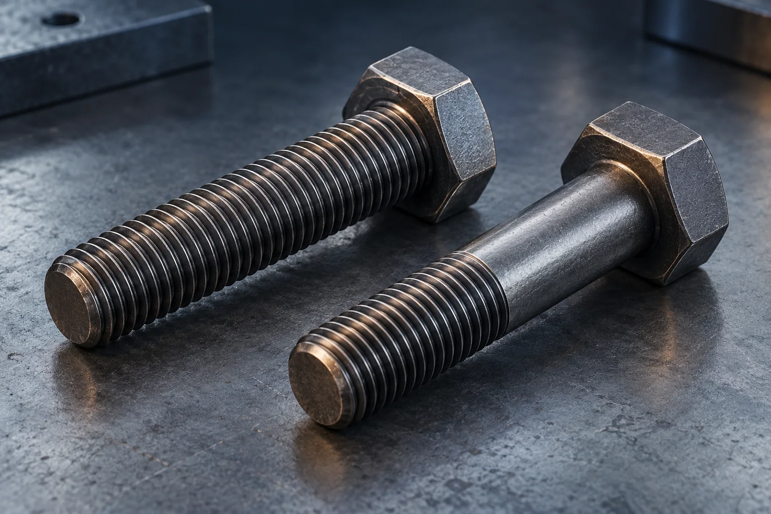
A structural bolt generally has three relevant axial regions: an unthreaded, full-diameter body; a transition region where the thread runs into that body; and the fully threaded portion. Their positions depend on the bolt’s overall length and thread geometry.
For a conventional partially threaded heavy hex structural bolt, let:
- L = nominal bolt length, measured from beneath the head.
- L_T = nominal threaded length measured from the bolt end, as represented in the applicable dimensional reference.
- Y = thread transition length.
Using the nominal geometry illustrated in RCSC 2025 Figure C-2.2, the approximate distance from the underside of the head to the beginning of the thread transition is:
Nominal body-region length = L − L_T − Y
The distance from beneath the head to the beginning of the full-thread region is:
L − L_T
These dimensions serve different checks. Subtracting only the full-thread length ignores the transition region and can overstate the portion of the bolt that is available as an unquestionably unthreaded body.
A shear plane is commonly located at an interface where connected steel elements transfer shear. Its axial position can be measured from beneath the bolt head by adding the thicknesses of any head-side washers and the connected material between the head and that interface.
The resulting shear-plane position can then be compared with the bolt’s actual body and thread geometry.
Threads included versus threads excluded
A structural connection does not universally require the threads to be excluded from the shear plane. Both threads-included and threads-excluded conditions are recognized in structural bolting design, and the applicable assumption determines which shear-resistance provisions the designer uses.
The Engineer of Record must identify where thread exclusion is required. RCSC 2025 Section 1.6 addresses this information in the contract documents, while Section 5.1 provides the corresponding shear-strength framework.
When threads are included, the design must use the applicable threads-included provisions. When they are specified as excluded, the installed assembly must support that assumption. A length-table result alone does not establish it.
The thread transition deserves particular attention. RCSC 2025 Commentary to Section 2.7 explains that earlier treatment of shear planes within this region was less conservative. The current approach requires more care because the transition geometry and permitted manufacturing variations do not justify treating that region as ordinary unthreaded body without further qualification.
This also explains why visually finding a short smooth region on a bolt is not sufficient evidence of threads-excluded performance. Certain short structural bolts are required to be fully threaded under the applicable dimensional rules, and special thread configurations can differ from standard partly threaded bolts. The actual product configuration must be identified before applying a conventional shank-length calculation.
Bolt orientation can change the result
Consider a two-plate connection with unequal plate thicknesses. If the bolt head is on the thinner-plate side, the plate interface is closer to the underside of the head. Reverse the bolt, and that same interface moves farther from the head.
The bolt length, grip and nut configuration may all remain unchanged. Yet the position of the shear plane relative to the unthreaded shank can change.
Adding a washer beneath the bolt head creates a similar effect by moving the steel stack away from the head. A connection initially checked with no head-side washer should not automatically retain its threads-excluded classification after an additional washer is introduced.
This is not merely an installation preference. RCSC 2025 includes requirements related to bolt orientation and notification when head-side washers are added to assemblies whose design depends on thread exclusion.
Where a bolt crosses more than one shear plane, each interface must be considered. RCSC’s design treatment is conservative when threads are present in one of multiple shear planes; it does not simply allow a designer to treat the remaining planes as independently satisfying the more favorable threads-excluded condition.
The practical rule is to evaluate the thread position against the design assumption for the complete connection—not to infer that assumption from the bolt length or the appearance of one shear plane.
Verify the Selected Length Against the Actual Bolt Assembly
The previous calculation produced a 2 1/4 in. candidate. The following hypothetical example shows why it still needs a thread-position check.
Illustrative hypothetical example — not a SUNHY customer project or verified product assembly
Assume a steel connection with:
| Item | Assumed dimension or condition |
|---|---|
| Bolt diameter | 3/4 in. |
| Plate adjacent to bolt head | 1/2 in. |
| Plate adjacent to nut | 5/8 in. |
| Total grip | 1 1/8 in. |
| Washer | One standard ASTM F436 washer beneath the nut |
| Head-side washer | None |
| Initial bolt length | 2 1/4 in. |
| Alternative candidate | 2 1/2 in. |
For the geometry comparison, the nominal dimensions in RCSC 2025 Commentary Table C-2.1 for the selected diameter are:
- Thread length, L_T = 1 3/8 in.
- Transition length, Y = 1/4 in.
- Heavy hex nut height, H₂ = 47/64 in.
These are reference dimensions, not a complete dimensional tolerance inspection of any manufactured bolt.
Check the 2 1/4 in. candidate
The nominal full-body region ahead of the transition is:
2.25 − 1.375 − 0.250 = 0.625 in.
With the 1/2 in. plate next to the bolt head, the shear plane at the plate interface is 0.500 in. from the underside of the head. It is nominally 0.125 in. before the calculated beginning of the transition.
Now reverse the bolt while keeping the same grip and washer arrangement. The 5/8 in. plate lies next to the bolt head, placing the interface 0.625 in. from the underside of the head.
That position coincides with the nominal start of the transition region.
Therefore, the initial 2 1/4 in. selection cannot be taken as proof that the reversed arrangement meets a threads-excluded design requirement. Permitted dimensional variations and the actual bolt geometry must be considered.
Check the 2 1/2 in. candidate
For the longer bolt, using the same nominal threaded and transition lengths:
2.50 − 1.375 − 0.250 = 0.875 in.
Both possible plate-interface locations—0.500 and 0.625 in. from the head—would lie before the nominal transition region in this simplified geometry.
The longer candidate therefore offers more nominal clearance between the specified shear plane and the transition region. However, that observation does not establish final compliance: actual dimensional tolerances, the applicable bolt configuration and the connection design still control the decision.
Check nut engagement and end projection
The nut-side washer begins beyond the 1.125 in. grip. Adding its 0.15625 in. allowance and the nominal nut height of 47/64 in. gives a nominal distance to the outside face of the nut of:
1.125 + 0.15625 + 0.734375 = 2.015625 in.
Assuming full seating of the specified components, the nominal bolt-end projections would be:
- 2 1/4 in. bolt: 2.250000 − 2.015625 = 0.234375 in.
- 2 1/2 in. bolt: 2.500000 − 2.015625 = 0.484375 in.
The arithmetic establishes the geometric difference between these two candidates. It does not, by itself, demonstrate compliant thread engagement or prescribe an allowable end projection. The nut must engage the actual threaded section without being stopped by the runout, and any relevant installation or clearance requirements must still be checked.
This example produces a useful selection distinction: the 2 1/4 in. bolt is the initial result of the length-selection method, while the 2 1/2 in. candidate provides a different nominal thread-position relationship. Which candidate is acceptable depends on the approved design, the actual bolting components and the required assembly configuration.
If the design requires thread exclusion, changing bolt orientation, washer location or the selected length cannot be treated as an informal field adjustment. The revised arrangement needs to remain consistent with the connection drawings and applicable engineering requirements.
A hypothetical trial assembly has acceptable nut engagement, yet a shear plane lies in the thread transition rather than the assumed smooth shank. Nominal overall length did not establish usable body length. Check the actual geometry and orientation against the approved shear assumption. The bolt measurement procedure supports identification; the connection drawing supplies the acceptance basis.
Specify the Length on the Structural Bolt Schedule or RFQ
After completing the geometric checks, translate the selection into information that a supplier and fabricator can use without having to guess which assembly was intended.
A structural bolt specification should identify the nominal diameter and length, applicable product grade, type and style, required standards and their governing editions, and the corresponding nut and washer configuration. The coating or finish also needs to be identified because the components must form an appropriate compatible bolting assembly.
For a connection whose design depends on thread exclusion, the bolt schedule or accompanying connection documentation should also make the design assumption, required orientation and relevant washer positions clear. Listing only the diameter and overall length may not be enough to preserve the verified shear-plane arrangement.
For the hypothetical example, an incomplete purchasing description would simply say:
3/4 in. × 2 1/4 in. structural bolt
That does not establish the product grade or thread configuration, and it gives no indication that bolt orientation may affect the intended shear-plane condition.
A more useful purchasing record would identify the engineer-approved length together with the complete component specification and a reference to the connection detail showing the required installation arrangement. Any dimensional or inspection evidence requested from the supplier should be tied to the actual specified product and contract requirements.
Where a standard catalog length cannot satisfy both the necessary thread position and normal nut engagement, the decision may require review of washer arrangements, bolt orientation or an expressly approved special thread configuration. It should not be resolved by assuming that every available bolt of the same nominal diameter has the same usable shank geometry.
The final selection is not simply the nearest bolt length from a calculation. It is the length whose assembled geometry supports the specified connection design, including adequate nut engagement and the required relationship between the bolt threads and shear planes.
Technical basis
The principal reference for the selection method and thread-position discussion is the RCSC Specification for Structural Joints Using High-Strength Bolts (June 5, 2025), particularly the requirements and commentary concerning component geometry, bolt-length selection, washer arrangements and shear-plane design. The relevant structural fastener dimensional standard is ASME B18.2.6, as referenced by RCSC. Specific procurement and engineering acceptance must follow the governing project documents and applicable standard editions.
Frequently asked questions
Does grip length include the bolt head?
No. Grip is the thickness of the connected material being clamped. Account for required washers and other hardware separately using the governing length-selection method.
Is enough nut engagement the only length check?
No. Also check washers, thread runout, usable body length, bolt orientation and the design assumption about threads at each shear plane.
Can a washer be removed to make a short bolt fit?
Only if the approved connection and installation requirements permit the revised arrangement. Otherwise obtain the correct bolt length and required components.