Quest'ultima verifica è importante perché un bullone può essere sufficientemente lungo per l'assemblaggio e tuttavia collocare le sue filettature, o la transizione tra il gambo liscio e le filettature, in un piano di taglio dove il progetto presuppone un corpo del bullone non filettato. Viceversa, selezionare un bullone più lungo solo per allontanare le filettature da un piano di taglio può creare una sporgenza superflua o interferire con il corretto impegno del dado. La lunghezza corretta deve soddisfare entrambe le condizioni.
Il metodo seguente si concentra sui bulloni strutturali esagonali pesanti della serie in pollici utilizzati nei collegamenti in acciaio, con riferimenti al RCSC 2025 Specifica per giunti strutturali con bulloni ad alta resistenza. Altre configurazioni di elementi di fissaggio, compresi i gruppi a controllo di tensione twist-off, i bulloni interamente filettati e le lunghezze di filettatura speciali, richiedono verifiche dimensionali specifiche.
Determinare la grip e lo spessore delle superfici di appoggio
La grip è lo spessore totale dei materiali collegati trattenuti tra la testa del bullone e il dado. Per un semplice collegamento a due piastre, è la somma dei due spessori delle piastre. Se il collegamento comprende piastre di giunzione o riempitivi all'interno del giunto serrato, devono essere inclusi anche i loro spessori applicabili.
Si considerino due piastre in acciaio, una spessa 1/2 in. e l'altra 5/8 in. La presa è:
Presa = 1/2 + 5/8 = 1 1/8 in.
In questo valore non sono comprese né l'altezza del dado né lo spessore della rondella. Questa distinzione è importante perché il metodo di selezione della lunghezza del bullone secondo RCSC 2025 parte dalla presa e considera separatamente le rondelle e la lunghezza aggiuntiva necessaria per il dado e le tolleranze di fabbricazione.
Un errore comune in fase di ordine è partire da una misura complessiva che include già una rondella e poi aggiungere di nuovo il margine per la rondella. Il bullone risultante può essere più lungo di quanto previsto dal metodo di selezione. L'errore opposto, ovvero misurare solo le piastre principali del collegamento e omettere uno spessore serrato, produce una presa sottostimata.
Anche la disposizione delle rondelle è importante, oltre al loro spessore totale. Una rondella sotto la testa del bullone allontana l'acciaio collegato dalla superficie di appoggio della testa. Una rondella sotto il dado aumenta la distanza che il dado deve percorrere lungo il bullone, ma non sposta allo stesso modo il piano di taglio tra piastra e piastra rispetto alla testa del bullone.
Questa differenza diventa significativa quando il progettista richiede che le filettature siano escluse dal piano di taglio.
Prima di calcolare la lunghezza, definire lo spessore effettivo del pacchetto:
- Tutte le piastre in acciaio collegate, le piastre di giunzione e gli spessori applicabili che contribuiscono alla presa.
- Il numero e il tipo di rondelle sotto la testa del bullone e il dado.
- Se il montaggio include un indicatore diretto di tensione, una rondella smussata, una rondella di reazione o un altro componente speciale.
- L'orientamento previsto del bullone, soprattutto se le piastre collegate hanno spessori diversi.
Washer requirements are not identical for every structural joint. RCSC 2025 Section 6 addresses washer use under different installation and connection conditions. The actual configuration should come from the project documents and the applicable bolting procedure rather than from an assumed rule that every connection uses one washer in the same location.
In una revisione illustrativa del progetto, una piastra di riempimento viene aggiunta dopo l'emissione della distinta dei bulloni. Il bullone ordinato potrebbe non garantire più l'impegno filettato richiesto perché lo spessore totale del serraggio è cambiato. Aggiornare gli spessori dell'acciaio e ogni componente di appoggio necessario, selezionare una nuova lunghezza candidata e verificare la posizione effettiva della filettatura. Non compensare omettendo una rondella specificata.
Calcolare una lunghezza di prova del bullone da grip, rondelle e tolleranze del dado
Per i bulloni strutturali esagonali pesanti convenzionali della serie in pollici coperti dalla guida RCSC 2025 per la selezione della lunghezza, il calcolo iniziale può essere espresso come:
Lunghezza di prova del bullone = Spessore del serraggio + Tolleranze applicabili della bulloneria + Aggiunta di lunghezza in base al diametro
I tre termini hanno scopi diversi.
Spessore del serraggio rappresenta lo spessore del materiale collegato. Sovrametalli per la bulloneria tengono conto dello spessore aggiuntivo delle rondelle o dei dispositivi di indicazione specificati. Il maggiorazione di lunghezza in base al diametro is taken from RCSC 2025 Commentary Table C-2.2 and allows for normal heavy hex nut engagement and manufacturing tolerances in the referenced assembly.
Quest'ultimo termine non va confuso con l'altezza fisica del dado. Si tratta di un margine di selezione, non di un altro componente da impilare accanto a un margine separato pari all'altezza piena del dado.
Ad esempio, il Commentario RCSC 2025 prevede un'aggiunta di 1 in. alla lunghezza per un bullone con diametro nominale di 3/4 in. Per ogni rondella ASTM F436 standard presente nell'assemblaggio, il metodo di selezione indicato aggiunge 5/32 in. Una rondella extra-spessa o un altro dispositivo approvato ha un margine diverso, pertanto sostituire un tipo di rondella con un altro senza rivedere il calcolo può modificare la scelta della lunghezza.
Il calcolo per un bullone da 3/4 in. con un grip di 1 1/8 in. e una rondella standard F436 è quindi:
Lunghezza di prova = 1 1/8 + 5/32 + 1 = 2 9/32 in.
In forma decimale:
1.125 + 0.15625 + 1.000 = 2.28125 in.
Secondo la procedura del Commentario RCSC 2025, questo risultato preliminare viene arrotondato all'incremento di 1/4 in. più vicino per lunghezze del bullone non superiori a 6 in. Il candidato iniziale è quindi 2 1/4 in.
Per questo motivo, trattare il risultato come un minimo che deve essere sempre arrotondato per eccesso non equivale a seguire il metodo del Commento RCSC indicato. Né il valore arrotondato dovrebbe essere accettato automaticamente solo perché è la lunghezza nominale più vicina.
Se il giunto utilizza più rondelle, un diverso dispositivo indicatore o bulloneria speciale, la relativa tolleranza deve essere ricalcolata. Se si considera un candidato più lungo, deve essere verificata anche la nuova geometria.
Il valore selezionato le dimensioni dell'elemento di fissaggio devono corrispondere al tipo di bullone specificato e ai requisiti del prodotto. ASTM F3125/F3125M riguarda i prodotti di bulloneria strutturale applicabili, mentre ASME B18.2.6 fornisce i requisiti dimensionali per gli elementi di fissaggio strutturali. La specifica RCSC ne disciplina l'impiego nei giunti strutturali. Si tratta di responsabilità correlate ma distinte; citare una norma non sostituisce la verifica delle altre, ove applicabili.
Verificare se le filettature cadono all'interno dei piani di taglio
La scelta della lunghezza diventa più complessa quando il collegamento è progettato con le filettature escluse dal piano di taglio.
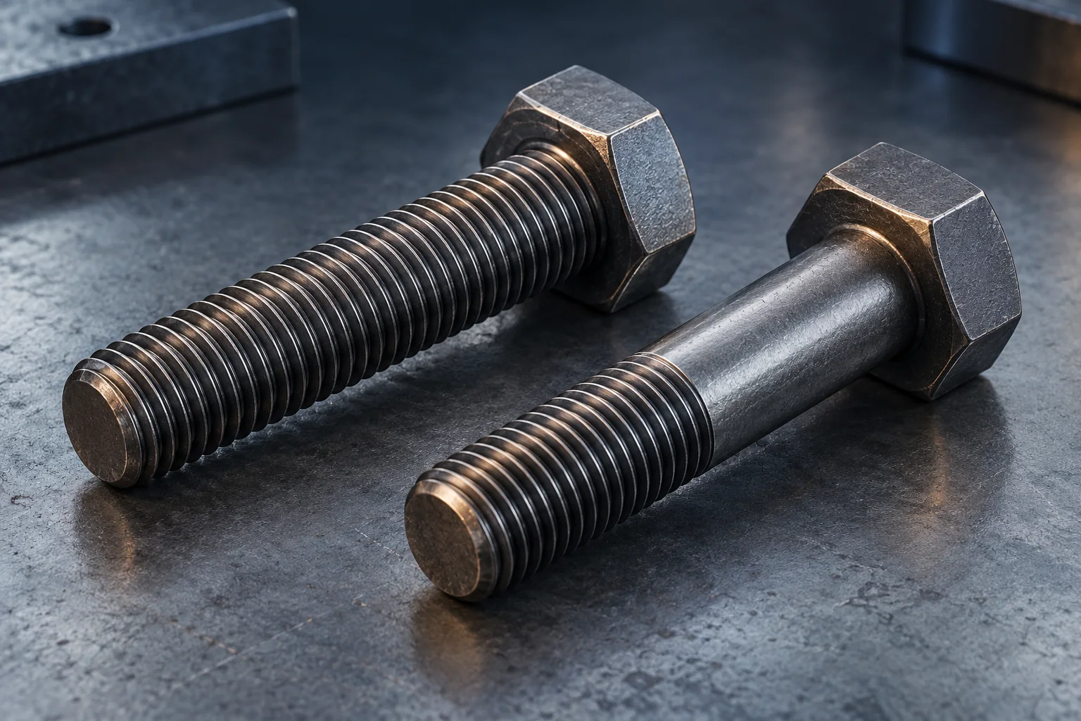
A structural bolt generally has three relevant axial regions: an unthreaded, full-diameter body; a transition region where the thread runs into that body; and the fully threaded portion. Their positions depend on the bolt’s overall length and thread geometry.
For a conventional partially threaded heavy hex structural bolt, let:
- L = nominal bolt length, measured from beneath the head.
- L_T = nominal threaded length measured from the bolt end, as represented in the applicable dimensional reference.
- Y = thread transition length.
Using the nominal geometry illustrated in RCSC 2025 Figure C-2.2, the approximate distance from the underside of the head to the beginning of the thread transition is:
Nominal body-region length = L − L_T − Y
The distance from beneath the head to the beginning of the full-thread region is:
L − L_T
These dimensions serve different checks. Subtracting only the full-thread length ignores the transition region and can overstate the portion of the bolt that is available as an unquestionably unthreaded body.
A shear plane is commonly located at an interface where connected steel elements transfer shear. Its axial position can be measured from beneath the bolt head by adding the thicknesses of any head-side washers and the connected material between the head and that interface.
The resulting shear-plane position can then be compared with the bolt’s actual body and thread geometry.
Threads included versus threads excluded
A structural connection does not universally require the threads to be excluded from the shear plane. Both threads-included and threads-excluded conditions are recognized in structural bolting design, and the applicable assumption determines which shear-resistance provisions the designer uses.
The Engineer of Record must identify where thread exclusion is required. RCSC 2025 Section 1.6 addresses this information in the contract documents, while Section 5.1 provides the corresponding shear-strength framework.
When threads are included, the design must use the applicable threads-included provisions. When they are specified as excluded, the installed assembly must support that assumption. A length-table result alone does not establish it.
The thread transition deserves particular attention. RCSC 2025 Commentary to Section 2.7 explains that earlier treatment of shear planes within this region was less conservative. The current approach requires more care because the transition geometry and permitted manufacturing variations do not justify treating that region as ordinary unthreaded body without further qualification.
This also explains why visually finding a short smooth region on a bolt is not sufficient evidence of threads-excluded performance. Certain short structural bolts are required to be fully threaded under the applicable dimensional rules, and special thread configurations can differ from standard partly threaded bolts. The actual product configuration must be identified before applying a conventional shank-length calculation.
Bolt orientation can change the result
Consider a two-plate connection with unequal plate thicknesses. If the bolt head is on the thinner-plate side, the plate interface is closer to the underside of the head. Reverse the bolt, and that same interface moves farther from the head.
The bolt length, grip and nut configuration may all remain unchanged. Yet the position of the shear plane relative to the unthreaded shank can change.
Adding a washer beneath the bolt head creates a similar effect by moving the steel stack away from the head. A connection initially checked with no head-side washer should not automatically retain its threads-excluded classification after an additional washer is introduced.
This is not merely an installation preference. RCSC 2025 includes requirements related to bolt orientation and notification when head-side washers are added to assemblies whose design depends on thread exclusion.
Where a bolt crosses more than one shear plane, each interface must be considered. RCSC’s design treatment is conservative when threads are present in one of multiple shear planes; it does not simply allow a designer to treat the remaining planes as independently satisfying the more favorable threads-excluded condition.
The practical rule is to evaluate the thread position against the design assumption for the complete connection—not to infer that assumption from the bolt length or the appearance of one shear plane.
Verificare la lunghezza selezionata rispetto all'effettivo assemblaggio del bullone
The previous calculation produced a 2 1/4 in. candidate. The following hypothetical example shows why it still needs a thread-position check.
Illustrative hypothetical example — not a SUNHY customer project or verified product assembly
Assume a steel connection with:
| Elemento | Assumed dimension or condition |
|---|---|
| Bolt diameter | 3/4 in. |
| Plate adjacent to bolt head | 1/2 pollice. |
| Plate adjacent to nut | 5/8 in. |
| Total grip | 1 1/8 in. |
| Rondella | One standard ASTM F436 washer beneath the nut |
| Head-side washer | Nessuno |
| Initial bolt length | 2 1/4 in. |
| Alternative candidate | 2 1/2 in. |
For the geometry comparison, the nominal dimensions in RCSC 2025 Commentary Table C-2.1 for the selected diameter are:
- Thread length, L_T = 1 3/8 in.
- Transition length, Y = 1/4 in.
- Heavy hex nut height, H₂ = 47/64 in.
These are reference dimensions, not a complete dimensional tolerance inspection of any manufactured bolt.
Check the 2 1/4 in. candidate
The nominal full-body region ahead of the transition is:
2.25 − 1.375 − 0.250 = 0.625 in.
With the 1/2 in. plate next to the bolt head, the shear plane at the plate interface is 0.500 in. from the underside of the head. It is nominally 0.125 in. before the calculated beginning of the transition.
Now reverse the bolt while keeping the same grip and washer arrangement. The 5/8 in. plate lies next to the bolt head, placing the interface 0.625 in. from the underside of the head.
That position coincides with the nominal start of the transition region.
Therefore, the initial 2 1/4 in. selection cannot be taken as proof that the reversed arrangement meets a threads-excluded design requirement. Permitted dimensional variations and the actual bolt geometry must be considered.
Check the 2 1/2 in. candidate
For the longer bolt, using the same nominal threaded and transition lengths:
2.50 − 1.375 − 0.250 = 0.875 in.
Both possible plate-interface locations—0.500 and 0.625 in. from the head—would lie before the nominal transition region in this simplified geometry.
The longer candidate therefore offers more nominal clearance between the specified shear plane and the transition region. However, that observation does not establish final compliance: actual dimensional tolerances, the applicable bolt configuration and the connection design still control the decision.
Check nut engagement and end projection
The nut-side washer begins beyond the 1.125 in. grip. Adding its 0.15625 in. allowance and the nominal nut height of 47/64 in. gives a nominal distance to the outside face of the nut of:
1.125 + 0.15625 + 0.734375 = 2.015625 in.
Assuming full seating of the specified components, the nominal bolt-end projections would be:
- 2 1/4 in. bolt: 2.250000 − 2.015625 = 0.234375 in.
- 2 1/2 in. bolt: 2.500000 − 2.015625 = 0.484375 in.
The arithmetic establishes the geometric difference between these two candidates. It does not, by itself, demonstrate compliant thread engagement or prescribe an allowable end projection. The nut must engage the actual threaded section without being stopped by the runout, and any relevant installation or clearance requirements must still be checked.
This example produces a useful selection distinction: the 2 1/4 in. bolt is the initial result of the length-selection method, while the 2 1/2 in. candidate provides a different nominal thread-position relationship. Which candidate is acceptable depends on the approved design, the actual bolting components and the required assembly configuration.
If the design requires thread exclusion, changing bolt orientation, washer location or the selected length cannot be treated as an informal field adjustment. The revised arrangement needs to remain consistent with the connection drawings and applicable engineering requirements.
A hypothetical trial assembly has acceptable nut engagement, yet a shear plane lies in the thread transition rather than the assumed smooth shank. Nominal overall length did not establish usable body length. Check the actual geometry and orientation against the approved shear assumption. The bolt measurement procedure supports identification; the connection drawing supplies the acceptance basis.
Specificare la lunghezza nella distinta dei bulloni strutturali o nella RFQ
After completing the geometric checks, translate the selection into information that a supplier and fabricator can use without having to guess which assembly was intended.
A structural bolt specification should identify the nominal diameter and length, applicable product grade, type and style, required standards and their governing editions, and the corresponding nut and washer configuration. The coating or finish also needs to be identified because the components must form an appropriate compatible bolting assembly.
For a connection whose design depends on thread exclusion, the bolt schedule or accompanying connection documentation should also make the design assumption, required orientation and relevant washer positions clear. Listing only the diameter and overall length may not be enough to preserve the verified shear-plane arrangement.
For the hypothetical example, an incomplete purchasing description would simply say:
3/4 in. × 2 1/4 in. structural bolt
That does not establish the product grade or thread configuration, and it gives no indication that bolt orientation may affect the intended shear-plane condition.
A more useful purchasing record would identify the engineer-approved length together with the complete component specification and a reference to the connection detail showing the required installation arrangement. Any dimensional or inspection evidence requested from the supplier should be tied to the actual specified product and contract requirements.
Where a standard catalog length cannot satisfy both the necessary thread position and normal nut engagement, the decision may require review of washer arrangements, bolt orientation or an expressly approved special thread configuration. It should not be resolved by assuming that every available bolt of the same nominal diameter has the same usable shank geometry.
The final selection is not simply the nearest bolt length from a calculation. It is the length whose assembled geometry supports the specified connection design, including adequate nut engagement and the required relationship between the bolt threads and shear planes.
Technical basis
The principal reference for the selection method and thread-position discussion is the RCSC Specification for Structural Joints Using High-Strength Bolts (June 5, 2025), particularly the requirements and commentary concerning component geometry, bolt-length selection, washer arrangements and shear-plane design. The relevant structural fastener dimensional standard is ASME B18.2.6, as referenced by RCSC. Specific procurement and engineering acceptance must follow the governing project documents and applicable standard editions.
Domande frequenti
La lunghezza di serraggio include la testa del bullone?
Il n. Grip indica lo spessore del materiale collegato che viene serrato. Considerare separatamente le rondelle e gli altri elementi di fissaggio richiesti utilizzando il metodo di selezione della lunghezza applicabile.
È sufficiente il solo impegno del dado come unico controllo di lunghezza?
No. Verificare anche le rondelle, il filetto incompleto, la lunghezza utile del gambo, l'orientamento dei bulloni e l'ipotesi progettuale relativa ai filetti su ciascun piano di taglio.
È possibile rimuovere una rondella per adattare un bullone corto?
Solo se i requisiti approvati di connessione e installazione consentono la disposizione modificata. In caso contrario, procurarsi la lunghezza corretta dei bulloni e i componenti necessari.