Esta última comprobación es importante porque un tornillo puede ser lo bastante largo para montarse y, aun así, situar sus roscas, o la transición entre su vástago liso y las roscas, en un plano de cortante donde el diseño supone un cuerpo de tornillo sin roscar. Por el contrario, seleccionar un tornillo más largo solo para alejar las roscas de un plano de cortante puede crear una proyección innecesaria o interferir con el roscado correcto de la tuerca. La longitud correcta debe cumplir ambas condiciones.
El método siguiente se centra en tornillos estructurales hexagonales pesados de la serie en pulgadas utilizados en uniones de acero, con referencias al RCSC 2025 Especificación para uniones estructurales con pernos de alta resistencia. Otras configuraciones de elementos de fijación, incluidas las unidades de control de tensión por rotura de tuerca, los tornillos totalmente roscados y las longitudes de rosca especiales, requieren sus propias comprobaciones dimensionales.
Establezca el agarre y la pila de superficies de apoyo
El agarre es el espesor total de los materiales unidos que quedan retenidos entre la cabeza del tornillo y la tuerca. En una unión sencilla de dos placas, es la suma de los espesores de ambas placas. Cuando la unión incluye placas de empalme o suplementos dentro de la junta apretada, también deben incluirse sus espesores aplicables.
Consider two steel plates, one 1/2 in. thick and the other 5/8 in. thick. The grip is:
Agarre = 1/2 + 5/8 = 1 1/8 in.
Ni la altura de la tuerca ni el espesor de la arandela se incluyen en esa cifra. Esta distinción es importante porque el método de selección de longitud de perno de la RCSC 2025 parte del agarre y luego tiene en cuenta por separado las arandelas y la longitud adicional necesaria para la tuerca y las tolerancias de fabricación.
Un error habitual al realizar el pedido es partir de una medición total que ya incluye una arandela y luego volver a sumar el margen de la arandela. El perno resultante puede ser más largo de lo que pretendía el método de selección. El error contrario —medir solo las placas de conexión principales y omitir un relleno aprisionado— da como resultado una longitud de agarre subestimada.
La disposición de las arandelas también importa más allá de su espesor total. Una arandela bajo la cabeza del perno aleja el acero conectado de la superficie de apoyo de la cabeza. Una arandela bajo la tuerca aumenta la distancia que la tuerca debe recorrer a lo largo del perno, pero no desplaza el plano de cortante placa-placa respecto a la cabeza del perno de la misma manera.
Esta diferencia adquiere importancia cuando el diseñador exige que las roscas queden excluidas del plano de cortante.
Antes de calcular la longitud, determine la composición real del apilamiento:
- Todas las placas de acero conectadas, placas de empalme y suplementos aplicables que contribuyen al agarre.
- El número y tipo de arandelas bajo la cabeza del tornillo y la tuerca.
- Si el conjunto incluye un indicador directo de tensión, una arandela biselada, una arandela de reacción u otro componente especial.
- La orientación prevista del perno, especialmente si las placas conectadas tienen espesores diferentes.
Washer requirements are not identical for every structural joint. RCSC 2025 Section 6 addresses washer use under different installation and connection conditions. The actual configuration should come from the project documents and the applicable bolting procedure rather than from an assumed rule that every connection uses one washer in the same location.
En una revisión ilustrativa del proyecto, se añade una placa de relleno después de emitido el listado de tornillos. Es posible que el tornillo pedido ya no proporcione el agarre requerido porque la pila de apriete ha cambiado. Actualice los espesores de acero y todos los componentes de apoyo necesarios, seleccione una nueva longitud candidata y verifique la posición real de la rosca. No lo compense omitiendo una arandela especificada.
Calcule una longitud de tornillo de prueba a partir del agarre, las arandelas y los márgenes de tuerca
Para los tornillos estructurales de cabeza hexagonal pesada convencionales de la serie en pulgadas cubiertos por la guía de selección de longitud RCSC 2025, el cálculo inicial puede expresarse como:
Longitud de tornillo de prueba = Agarre + Tolerancias aplicables de los elementos de fijación + Adición de longitud en función del diámetro
Los tres términos tienen propósitos diferentes.
Agarre representa el espesor del material conectado. Tolerancias de ferretería tener en cuenta el espesor adicional de las arandelas o dispositivos indicadores especificados. El adición de longitud basada en el diámetro is taken from RCSC 2025 Commentary Table C-2.2 and allows for normal heavy hex nut engagement and manufacturing tolerances in the referenced assembly.
Ese último término no debe confundirse con la altura física de la tuerca. Es un margen de selección, no otro componente que deba apilarse junto a un margen independiente equivalente a la altura completa de la tuerca.
Por ejemplo, el Comentario RCSC 2025 añade 1 in. de longitud para un diámetro nominal de perno de 3/4 in. Por cada arandela estándar ASTM F436 en el conjunto, su método de selección indicado añade 5/32 in. Una arandela extragruesa u otro dispositivo aprobado tiene una tolerancia diferente, por lo que sustituir un tipo de arandela por otro sin revisar el cálculo puede modificar la selección de longitud.
El cálculo para un perno de 3/4 in. con un agarre de 1 1/8 in. y una arandela estándar F436 es, por tanto:
Longitud de prueba = 1 1/8 + 5/32 + 1 = 2 9/32 in.
En forma decimal:
1.125 + 0.15625 + 1.000 = 2.28125 in.
Según el procedimiento del Comentario de la RCSC 2025, este resultado preliminar se ajusta al incremento de 1/4 in. más próximo para longitudes de perno que no superen 6 in. El candidato inicial es, por tanto, 2 1/4 in.
Por esta razón, tratar el resultado como un mínimo que siempre debe redondearse hacia arriba no equivale a seguir el método del Comentario de la RCSC indicado. Tampoco debe aceptarse automáticamente el valor redondeado solo por ser la longitud nominal más próxima.
Si la unión utiliza más arandelas, un dispositivo indicador diferente o tornillería especial, debe recalcularse su tolerancia. Si se considera un candidato más largo, también debe verificarse la nueva geometría.
Las dimensiones del elemento de fijación seleccionado deben corresponder al tipo de perno especificado y a los requisitos del producto. ASTM F3125/F3125M abarca los productos de tornillería estructural aplicables, mientras que ASME B18.2.6 establece los requisitos dimensionales para elementos de fijación estructurales. La especificación RCSC aborda su uso en uniones estructurales. Son responsabilidades relacionadas pero distintas; citar una norma no sustituye la verificación de las demás cuando corresponda.
Compruebe si las roscas quedan dentro de los planos de cortante
La selección de la longitud se complica cuando la unión se diseña con las roscas excluidas del plano de cortante.
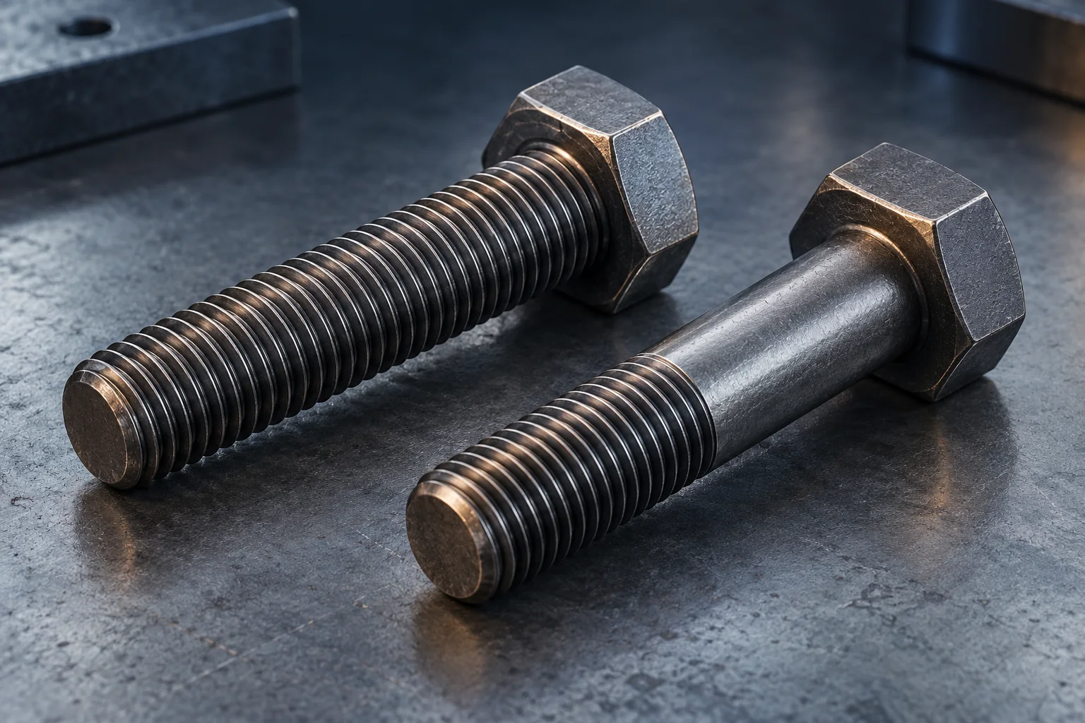
A structural bolt generally has three relevant axial regions: an unthreaded, full-diameter body; a transition region where the thread runs into that body; and the fully threaded portion. Their positions depend on the bolt’s overall length and thread geometry.
For a conventional partially threaded heavy hex structural bolt, let:
- L = nominal bolt length, measured from beneath the head.
- L_T = nominal threaded length measured from the bolt end, as represented in the applicable dimensional reference.
- Y = thread transition length.
Using the nominal geometry illustrated in RCSC 2025 Figure C-2.2, the approximate distance from the underside of the head to the beginning of the thread transition is:
Nominal body-region length = L − L_T − Y
The distance from beneath the head to the beginning of the full-thread region is:
L − L_T
These dimensions serve different checks. Subtracting only the full-thread length ignores the transition region and can overstate the portion of the bolt that is available as an unquestionably unthreaded body.
A shear plane is commonly located at an interface where connected steel elements transfer shear. Its axial position can be measured from beneath the bolt head by adding the thicknesses of any head-side washers and the connected material between the head and that interface.
The resulting shear-plane position can then be compared with the bolt’s actual body and thread geometry.
Threads included versus threads excluded
A structural connection does not universally require the threads to be excluded from the shear plane. Both threads-included and threads-excluded conditions are recognized in structural bolting design, and the applicable assumption determines which shear-resistance provisions the designer uses.
The Engineer of Record must identify where thread exclusion is required. RCSC 2025 Section 1.6 addresses this information in the contract documents, while Section 5.1 provides the corresponding shear-strength framework.
When threads are included, the design must use the applicable threads-included provisions. When they are specified as excluded, the installed assembly must support that assumption. A length-table result alone does not establish it.
The thread transition deserves particular attention. RCSC 2025 Commentary to Section 2.7 explains that earlier treatment of shear planes within this region was less conservative. The current approach requires more care because the transition geometry and permitted manufacturing variations do not justify treating that region as ordinary unthreaded body without further qualification.
This also explains why visually finding a short smooth region on a bolt is not sufficient evidence of threads-excluded performance. Certain short structural bolts are required to be fully threaded under the applicable dimensional rules, and special thread configurations can differ from standard partly threaded bolts. The actual product configuration must be identified before applying a conventional shank-length calculation.
Bolt orientation can change the result
Consider a two-plate connection with unequal plate thicknesses. If the bolt head is on the thinner-plate side, the plate interface is closer to the underside of the head. Reverse the bolt, and that same interface moves farther from the head.
The bolt length, grip and nut configuration may all remain unchanged. Yet the position of the shear plane relative to the unthreaded shank can change.
Adding a washer beneath the bolt head creates a similar effect by moving the steel stack away from the head. A connection initially checked with no head-side washer should not automatically retain its threads-excluded classification after an additional washer is introduced.
This is not merely an installation preference. RCSC 2025 includes requirements related to bolt orientation and notification when head-side washers are added to assemblies whose design depends on thread exclusion.
Where a bolt crosses more than one shear plane, each interface must be considered. RCSC’s design treatment is conservative when threads are present in one of multiple shear planes; it does not simply allow a designer to treat the remaining planes as independently satisfying the more favorable threads-excluded condition.
The practical rule is to evaluate the thread position against the design assumption for the complete connection—not to infer that assumption from the bolt length or the appearance of one shear plane.
Verifique la longitud seleccionada con el conjunto de tornillo real
The previous calculation produced a 2 1/4 in. candidate. The following hypothetical example shows why it still needs a thread-position check.
Illustrative hypothetical example — not a SUNHY customer project or verified product assembly
Assume a steel connection with:
| Elemento | Assumed dimension or condition |
|---|---|
| Bolt diameter | 3/4 in. |
| Plate adjacent to bolt head | 1/2 pulg. |
| Plate adjacent to nut | 5/8 in. |
| Total grip | 1 1/8 in. |
| Arandela | One standard ASTM F436 washer beneath the nut |
| Head-side washer | Ninguno |
| Initial bolt length | 2 1/4 in. |
| Alternative candidate | 2 1/2 in. |
For the geometry comparison, the nominal dimensions in RCSC 2025 Commentary Table C-2.1 for the selected diameter are:
- Thread length, L_T = 1 3/8 in.
- Transition length, Y = 1/4 in.
- Heavy hex nut height, H₂ = 47/64 in.
These are reference dimensions, not a complete dimensional tolerance inspection of any manufactured bolt.
Check the 2 1/4 in. candidate
The nominal full-body region ahead of the transition is:
2.25 − 1.375 − 0.250 = 0.625 in.
With the 1/2 in. plate next to the bolt head, the shear plane at the plate interface is 0.500 in. from the underside of the head. It is nominally 0.125 in. before the calculated beginning of the transition.
Now reverse the bolt while keeping the same grip and washer arrangement. The 5/8 in. plate lies next to the bolt head, placing the interface 0.625 in. from the underside of the head.
That position coincides with the nominal start of the transition region.
Therefore, the initial 2 1/4 in. selection cannot be taken as proof that the reversed arrangement meets a threads-excluded design requirement. Permitted dimensional variations and the actual bolt geometry must be considered.
Check the 2 1/2 in. candidate
For the longer bolt, using the same nominal threaded and transition lengths:
2.50 − 1.375 − 0.250 = 0.875 in.
Both possible plate-interface locations—0.500 and 0.625 in. from the head—would lie before the nominal transition region in this simplified geometry.
The longer candidate therefore offers more nominal clearance between the specified shear plane and the transition region. However, that observation does not establish final compliance: actual dimensional tolerances, the applicable bolt configuration and the connection design still control the decision.
Check nut engagement and end projection
The nut-side washer begins beyond the 1.125 in. grip. Adding its 0.15625 in. allowance and the nominal nut height of 47/64 in. gives a nominal distance to the outside face of the nut of:
1.125 + 0.15625 + 0.734375 = 2.015625 in.
Assuming full seating of the specified components, the nominal bolt-end projections would be:
- 2 1/4 in. bolt: 2.250000 − 2.015625 = 0.234375 in.
- 2 1/2 in. bolt: 2.500000 − 2.015625 = 0.484375 in.
The arithmetic establishes the geometric difference between these two candidates. It does not, by itself, demonstrate compliant thread engagement or prescribe an allowable end projection. The nut must engage the actual threaded section without being stopped by the runout, and any relevant installation or clearance requirements must still be checked.
This example produces a useful selection distinction: the 2 1/4 in. bolt is the initial result of the length-selection method, while the 2 1/2 in. candidate provides a different nominal thread-position relationship. Which candidate is acceptable depends on the approved design, the actual bolting components and the required assembly configuration.
If the design requires thread exclusion, changing bolt orientation, washer location or the selected length cannot be treated as an informal field adjustment. The revised arrangement needs to remain consistent with the connection drawings and applicable engineering requirements.
A hypothetical trial assembly has acceptable nut engagement, yet a shear plane lies in the thread transition rather than the assumed smooth shank. Nominal overall length did not establish usable body length. Check the actual geometry and orientation against the approved shear assumption. The bolt measurement procedure supports identification; the connection drawing supplies the acceptance basis.
Especifique la longitud en la lista de tornillos estructurales o en la solicitud de oferta
After completing the geometric checks, translate the selection into information that a supplier and fabricator can use without having to guess which assembly was intended.
A structural bolt specification should identify the nominal diameter and length, applicable product grade, type and style, required standards and their governing editions, and the corresponding nut and washer configuration. The coating or finish also needs to be identified because the components must form an appropriate compatible bolting assembly.
For a connection whose design depends on thread exclusion, the bolt schedule or accompanying connection documentation should also make the design assumption, required orientation and relevant washer positions clear. Listing only the diameter and overall length may not be enough to preserve the verified shear-plane arrangement.
For the hypothetical example, an incomplete purchasing description would simply say:
3/4 in. × 2 1/4 in. structural bolt
That does not establish the product grade or thread configuration, and it gives no indication that bolt orientation may affect the intended shear-plane condition.
A more useful purchasing record would identify the engineer-approved length together with the complete component specification and a reference to the connection detail showing the required installation arrangement. Any dimensional or inspection evidence requested from the supplier should be tied to the actual specified product and contract requirements.
Where a standard catalog length cannot satisfy both the necessary thread position and normal nut engagement, the decision may require review of washer arrangements, bolt orientation or an expressly approved special thread configuration. It should not be resolved by assuming that every available bolt of the same nominal diameter has the same usable shank geometry.
The final selection is not simply the nearest bolt length from a calculation. It is the length whose assembled geometry supports the specified connection design, including adequate nut engagement and the required relationship between the bolt threads and shear planes.
Technical basis
The principal reference for the selection method and thread-position discussion is the RCSC Specification for Structural Joints Using High-Strength Bolts (June 5, 2025), particularly the requirements and commentary concerning component geometry, bolt-length selection, washer arrangements and shear-plane design. The relevant structural fastener dimensional standard is ASME B18.2.6, as referenced by RCSC. Specific procurement and engineering acceptance must follow the governing project documents and applicable standard editions.
Preguntas frecuentes
¿La longitud de agarre incluye la cabeza del tornillo?
El n.º de agarre es el espesor del material conectado que se sujeta. Tenga en cuenta las arandelas y demás elementos de fijación necesarios por separado mediante el método de selección de longitud aplicable.
¿Es suficiente el contacto de la tuerca la única comprobación de longitud?
No. Compruebe también las arandelas, el descentramiento de rosca, la longitud útil del cuerpo, la orientación del tornillo y la hipótesis de diseño sobre las roscas en cada plano de corte.
¿Se puede quitar una arandela para que encaje un perno corto?
Solo si los requisitos aprobados de conexión e instalación permiten la disposición revisada. En caso contrario, obtenga la longitud de perno correcta y los componentes necesarios.