Cette dernière vérification est importante car un boulon peut être assez long pour être assemblé tout en plaçant ses filets, ou la transition entre sa tige lisse et ses filets, au niveau d'un plan de cisaillement où la conception suppose un corps de boulon non fileté. À l'inverse, choisir un boulon plus long simplement pour éloigner les filets d'un plan de cisaillement peut créer un dépassement inutile ou gêner un engagement correct de l'écrou. La longueur correcte doit satisfaire aux deux conditions.
La méthode ci-dessous porte sur les boulons de construction à tête hexagonale lourde de la série en pouces utilisés dans les assemblages en acier, avec des références au RCSC 2025 Spécification pour les assemblages structuraux utilisant des boulons à haute résistance. D'autres configurations de fixation, notamment les ensembles à contrôle de tension à tête cassante, les boulons entièrement filetés et les longueurs de filetage spéciales, nécessitent leurs propres vérifications dimensionnelles.
Établir la prise et l'empilement des surfaces d'appui
La prise est l'épaisseur totale des matériaux assemblés maintenus entre la tête du boulon et l'écrou. Pour un assemblage simple à deux plaques, il s'agit de la somme des deux épaisseurs de plaque. Lorsque l'assemblage comprend des éclisses ou des cales à l'intérieur du joint serré, leurs épaisseurs applicables doivent également être incluses.
Prenons deux plaques d'acier, l'une de 1/2 in. d'épaisseur et l'autre de 5/8 in. d'épaisseur. La prise est de :
Prise = 1/2 + 5/8 = 1 1/8 in.
Ni la hauteur de l'écrou ni l'épaisseur de la rondelle ne sont incluses dans cette valeur. Cette distinction est importante car la méthode de sélection de la longueur de boulon RCSC 2025 part de la prise, puis tient compte séparément des rondelles et de la longueur supplémentaire nécessaire pour l'écrou et les tolérances de fabrication.
Une erreur de commande courante consiste à partir d'une mesure globale incluant déjà une rondelle, puis à ajouter de nouveau la tolérance de rondelle. Le boulon obtenu peut alors être plus long que ce que prévoit la méthode de sélection. L'erreur inverse — mesurer uniquement les plaques principales de l'assemblage et omettre une cale serrée — conduit à une prise sous-estimée.
La disposition des rondelles importe également au-delà de leur épaisseur totale. Une rondelle sous la tête du boulon éloigne l'acier assemblé de la surface d'appui de la tête. Une rondelle sous l'écrou augmente la distance que l'écrou doit parcourir le long du boulon, mais ne déplace pas de la même manière le plan de cisaillement plaque-contre-plaque par rapport à la tête du boulon.
Cette différence devient significative lorsque le concepteur exige que les filets soient exclus du plan de cisaillement.
Avant de calculer la longueur, établir la pile réelle :
- Toutes les plaques d'acier assemblées, éclisses et cales applicables qui contribuent à la prise.
- Le nombre et le type de rondelles sous la tête du boulon et l'écrou.
- Si l'assemblage comprend un indicateur de tension direct, une rondelle chanfreinée, une rondelle de réaction ou un autre composant spécial.
- L'orientation prévue du boulon, en particulier si les plaques assemblées ont des épaisseurs différentes.
Washer requirements are not identical for every structural joint. RCSC 2025 Section 6 addresses washer use under different installation and connection conditions. The actual configuration should come from the project documents and the applicable bolting procedure rather than from an assumed rule that every connection uses one washer in the same location.
Dans une révision de site illustrative, une plaque d'appui est ajoutée après l'émission du plan de boulonnage. Le boulon commandé peut ne plus offrir la longueur de filetage engagée requise, car l'empilage serré a changé. Mettez à jour les épaisseurs d'acier et chaque composant d'appui requis, sélectionnez une nouvelle longueur candidate et vérifiez la position réelle du filetage. Ne compensez pas en omettant une rondelle spécifiée.
Calculer une longueur de boulon d'essai à partir de la prise, des rondelles et des tolérances d'écrou
Pour les boulons de structure à tête hexagonale lourde conventionnels de la série pouces couverts par les recommandations de sélection de longueur RCSC 2025, le calcul initial peut s'exprimer comme suit :
Longueur d'essai du boulon = serrage + tolérances applicables de la visserie + majoration de longueur liée au diamètre
Les trois termes ont des objectifs différents.
Serrage représente l'épaisseur du matériau assemblé. Tolérances pour la boulonnerie tiennent compte de l'épaisseur supplémentaire des rondelles ou des dispositifs indicateurs spécifiés. La majoration de longueur basée sur le diamètre is taken from RCSC 2025 Commentary Table C-2.2 and allows for normal heavy hex nut engagement and manufacturing tolerances in the referenced assembly.
Ce dernier terme ne doit pas être confondu avec la hauteur physique de l'écrou. Il s'agit d'une tolérance de sélection, et non d'un autre élément à empiler à côté d'une tolérance distincte de hauteur d'écrou complète.
Par exemple, le commentaire RCSC 2025 prévoit un ajout de longueur de 1 in. pour un diamètre nominal de boulon de 3/4 in. Pour chaque rondelle ASTM F436 standard dans l'assemblage, sa méthode de sélection indiquée ajoute 5/32 in. Une rondelle extra-épaisse ou un autre dispositif approuvé a une tolérance différente ; substituer un type de rondelle à un autre sans revoir le calcul peut donc modifier le choix de longueur.
Le calcul pour un boulon de 3/4 in. avec une prise de 1 1/8 in. et une rondelle F436 standard est donc :
Longueur d'essai = 1 1/8 + 5/32 + 1 = 2 9/32 in.
Sous forme décimale :
1.125 + 0.15625 + 1.000 = 2.28125 in.
Selon la procédure du commentaire RCSC 2025, ce résultat préliminaire est ajusté à l'incrément de 1/4 in. le plus proche pour les longueurs de boulon ne dépassant pas 6 in. Le candidat initial est donc 2 1/4 in.
Pour cette raison, traiter le résultat comme un minimum devant toujours être arrondi à la valeur supérieure n'équivaut pas à suivre la méthode du commentaire RCSC indiquée. La valeur arrondie ne doit pas non plus être acceptée automatiquement au seul motif qu'elle correspond à la longueur nominale la plus proche.
Si l'assemblage utilise davantage de rondelles, un dispositif indicateur différent ou une boulonnerie spéciale, sa tolérance doit être recalculée. Si un candidat plus long est envisagé, la nouvelle géométrie doit également être vérifiée.
Les dimensions du boulon sélectionné doivent correspondre au type de boulon spécifié et aux exigences du produit. L'ASTM F3125/F3125M traite des produits de boulonnerie structurale applicables, tandis que l'ASME B18.2.6 fournit les exigences dimensionnelles des éléments de fixation structuraux. La spécification RCSC traite de leur utilisation dans les assemblages structuraux. Ces responsabilités sont liées mais distinctes ; citer une norme ne remplace pas la vérification des autres lorsqu'elles s'appliquent.
Vérifier si les filets tombent dans les plans de cisaillement
Le choix de la longueur devient plus délicat lorsque l'assemblage est conçu avec les filets exclus du plan de cisaillement.
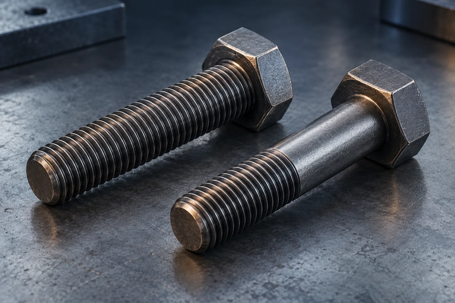
A structural bolt generally has three relevant axial regions: an unthreaded, full-diameter body; a transition region where the thread runs into that body; and the fully threaded portion. Their positions depend on the bolt’s overall length and thread geometry.
For a conventional partially threaded heavy hex structural bolt, let:
- L = nominal bolt length, measured from beneath the head.
- L_T = nominal threaded length measured from the bolt end, as represented in the applicable dimensional reference.
- Y = thread transition length.
Using the nominal geometry illustrated in RCSC 2025 Figure C-2.2, the approximate distance from the underside of the head to the beginning of the thread transition is:
Nominal body-region length = L − L_T − Y
The distance from beneath the head to the beginning of the full-thread region is:
L − L_T
These dimensions serve different checks. Subtracting only the full-thread length ignores the transition region and can overstate the portion of the bolt that is available as an unquestionably unthreaded body.
A shear plane is commonly located at an interface where connected steel elements transfer shear. Its axial position can be measured from beneath the bolt head by adding the thicknesses of any head-side washers and the connected material between the head and that interface.
The resulting shear-plane position can then be compared with the bolt’s actual body and thread geometry.
Threads included versus threads excluded
A structural connection does not universally require the threads to be excluded from the shear plane. Both threads-included and threads-excluded conditions are recognized in structural bolting design, and the applicable assumption determines which shear-resistance provisions the designer uses.
The Engineer of Record must identify where thread exclusion is required. RCSC 2025 Section 1.6 addresses this information in the contract documents, while Section 5.1 provides the corresponding shear-strength framework.
When threads are included, the design must use the applicable threads-included provisions. When they are specified as excluded, the installed assembly must support that assumption. A length-table result alone does not establish it.
The thread transition deserves particular attention. RCSC 2025 Commentary to Section 2.7 explains that earlier treatment of shear planes within this region was less conservative. The current approach requires more care because the transition geometry and permitted manufacturing variations do not justify treating that region as ordinary unthreaded body without further qualification.
This also explains why visually finding a short smooth region on a bolt is not sufficient evidence of threads-excluded performance. Certain short structural bolts are required to be fully threaded under the applicable dimensional rules, and special thread configurations can differ from standard partly threaded bolts. The actual product configuration must be identified before applying a conventional shank-length calculation.
Bolt orientation can change the result
Consider a two-plate connection with unequal plate thicknesses. If the bolt head is on the thinner-plate side, the plate interface is closer to the underside of the head. Reverse the bolt, and that same interface moves farther from the head.
The bolt length, grip and nut configuration may all remain unchanged. Yet the position of the shear plane relative to the unthreaded shank can change.
Adding a washer beneath the bolt head creates a similar effect by moving the steel stack away from the head. A connection initially checked with no head-side washer should not automatically retain its threads-excluded classification after an additional washer is introduced.
This is not merely an installation preference. RCSC 2025 includes requirements related to bolt orientation and notification when head-side washers are added to assemblies whose design depends on thread exclusion.
Where a bolt crosses more than one shear plane, each interface must be considered. RCSC’s design treatment is conservative when threads are present in one of multiple shear planes; it does not simply allow a designer to treat the remaining planes as independently satisfying the more favorable threads-excluded condition.
The practical rule is to evaluate the thread position against the design assumption for the complete connection—not to infer that assumption from the bolt length or the appearance of one shear plane.
Valider la longueur sélectionnée par rapport à l'assemblage réel du boulon
The previous calculation produced a 2 1/4 in. candidate. The following hypothetical example shows why it still needs a thread-position check.
Illustrative hypothetical example — not a SUNHY customer project or verified product assembly
Assume a steel connection with:
| Article | Assumed dimension or condition |
|---|---|
| Bolt diameter | 3/4 in. |
| Plate adjacent to bolt head | 1/2 po. |
| Plate adjacent to nut | 5/8 in. |
| Total grip | 1 1/8 in. |
| Washer | One standard ASTM F436 washer beneath the nut |
| Head-side washer | Aucun |
| Initial bolt length | 2 1/4 in. |
| Alternative candidate | 2 1/2 in. |
For the geometry comparison, the nominal dimensions in RCSC 2025 Commentary Table C-2.1 for the selected diameter are:
- Thread length, L_T = 1 3/8 in.
- Transition length, Y = 1/4 in.
- Heavy hex nut height, H₂ = 47/64 in.
These are reference dimensions, not a complete dimensional tolerance inspection of any manufactured bolt.
Check the 2 1/4 in. candidate
The nominal full-body region ahead of the transition is:
2.25 − 1.375 − 0.250 = 0.625 in.
With the 1/2 in. plate next to the bolt head, the shear plane at the plate interface is 0.500 in. from the underside of the head. It is nominally 0.125 in. before the calculated beginning of the transition.
Now reverse the bolt while keeping the same grip and washer arrangement. The 5/8 in. plate lies next to the bolt head, placing the interface 0.625 in. from the underside of the head.
That position coincides with the nominal start of the transition region.
Therefore, the initial 2 1/4 in. selection cannot be taken as proof that the reversed arrangement meets a threads-excluded design requirement. Permitted dimensional variations and the actual bolt geometry must be considered.
Check the 2 1/2 in. candidate
For the longer bolt, using the same nominal threaded and transition lengths:
2.50 − 1.375 − 0.250 = 0.875 in.
Both possible plate-interface locations—0.500 and 0.625 in. from the head—would lie before the nominal transition region in this simplified geometry.
The longer candidate therefore offers more nominal clearance between the specified shear plane and the transition region. However, that observation does not establish final compliance: actual dimensional tolerances, the applicable bolt configuration and the connection design still control the decision.
Check nut engagement and end projection
The nut-side washer begins beyond the 1.125 in. grip. Adding its 0.15625 in. allowance and the nominal nut height of 47/64 in. gives a nominal distance to the outside face of the nut of:
1.125 + 0.15625 + 0.734375 = 2.015625 in.
Assuming full seating of the specified components, the nominal bolt-end projections would be:
- 2 1/4 in. bolt: 2.250000 − 2.015625 = 0.234375 in.
- 2 1/2 in. bolt: 2.500000 − 2.015625 = 0.484375 in.
The arithmetic establishes the geometric difference between these two candidates. It does not, by itself, demonstrate compliant thread engagement or prescribe an allowable end projection. The nut must engage the actual threaded section without being stopped by the runout, and any relevant installation or clearance requirements must still be checked.
This example produces a useful selection distinction: the 2 1/4 in. bolt is the initial result of the length-selection method, while the 2 1/2 in. candidate provides a different nominal thread-position relationship. Which candidate is acceptable depends on the approved design, the actual bolting components and the required assembly configuration.
If the design requires thread exclusion, changing bolt orientation, washer location or the selected length cannot be treated as an informal field adjustment. The revised arrangement needs to remain consistent with the connection drawings and applicable engineering requirements.
A hypothetical trial assembly has acceptable nut engagement, yet a shear plane lies in the thread transition rather than the assumed smooth shank. Nominal overall length did not establish usable body length. Check the actual geometry and orientation against the approved shear assumption. The bolt measurement procedure supports identification; the connection drawing supplies the acceptance basis.
Spécifier la longueur sur le bordereau de boulons de construction ou la demande de prix
After completing the geometric checks, translate the selection into information that a supplier and fabricator can use without having to guess which assembly was intended.
A structural bolt specification should identify the nominal diameter and length, applicable product grade, type and style, required standards and their governing editions, and the corresponding nut and washer configuration. The coating or finish also needs to be identified because the components must form an appropriate compatible bolting assembly.
For a connection whose design depends on thread exclusion, the bolt schedule or accompanying connection documentation should also make the design assumption, required orientation and relevant washer positions clear. Listing only the diameter and overall length may not be enough to preserve the verified shear-plane arrangement.
For the hypothetical example, an incomplete purchasing description would simply say:
3/4 in. × 2 1/4 in. structural bolt
That does not establish the product grade or thread configuration, and it gives no indication that bolt orientation may affect the intended shear-plane condition.
A more useful purchasing record would identify the engineer-approved length together with the complete component specification and a reference to the connection detail showing the required installation arrangement. Any dimensional or inspection evidence requested from the supplier should be tied to the actual specified product and contract requirements.
Where a standard catalog length cannot satisfy both the necessary thread position and normal nut engagement, the decision may require review of washer arrangements, bolt orientation or an expressly approved special thread configuration. It should not be resolved by assuming that every available bolt of the same nominal diameter has the same usable shank geometry.
The final selection is not simply the nearest bolt length from a calculation. It is the length whose assembled geometry supports the specified connection design, including adequate nut engagement and the required relationship between the bolt threads and shear planes.
Technical basis
The principal reference for the selection method and thread-position discussion is the RCSC Specification for Structural Joints Using High-Strength Bolts (June 5, 2025), particularly the requirements and commentary concerning component geometry, bolt-length selection, washer arrangements and shear-plane design. The relevant structural fastener dimensional standard is ASME B18.2.6, as referenced by RCSC. Specific procurement and engineering acceptance must follow the governing project documents and applicable standard editions.
Questions fréquemment posées
La longueur de serrage inclut-elle la tête de boulon ?
Le n° de prise correspond à l'épaisseur du matériau assemblé serré. Tenir compte séparément des rondelles et autres éléments de fixation requis en utilisant la méthode de sélection de longueur applicable.
Un engagement d'écrou suffisant est-il le seul contrôle de longueur ?
Non. Vérifiez également les rondelles, la sortie de filetage, la longueur utile du corps, l'orientation des boulons et l'hypothèse de conception concernant les filets à chaque plan de cisaillement.
Peut-on retirer une rondelle pour qu'un boulon court s'adapte ?
Uniquement si les exigences approuvées de raccordement et d'installation permettent la configuration révisée. Sinon, procurez-vous la longueur de boulon correcte et les composants requis.