


 step-by-step")
To measure hex bolt dimensions correctly, verify three things in a fixed order: bolt length (under-the-head), thread major diameter, and thread pitch (metric pitch or imperial TPI). This is not “shop trivia.” A wrong pitch (for example M10×1.5 vs M10×1.25) can destroy the first two threads in seconds. Confusing thread diameter with head wrench size (WAF) leads to wrong parts on the purchase order, tool mismatch on site, and rework.
- Length controls grip (stack-up) and thread engagement.
- Diameter controls fit in the hole/nut and tensile stress area.
- Pitch/TPI controls compatibility with the nut or tapped hole—this is the #1 cause of cross-threading and “won’t fit” returns.
Below are the most common measurement errors that show up in field returns and incoming inspection rejects. Use a clean part, measure twice, and treat coatings (zinc, hot-dip galvanizing, PTFE) as a controlled variable—coatings change the effective diameter and can change thread fit.
| Common Measurement Errors in Ordering Hex Bolts |
|---|
| Measuring over dirt, debris, burrs, or damaged threads (false diameter/pitch reading). |
| Using too much force with calipers (springing the jaws and “shrinking” the reading). |
| Holding calipers at an angle (cosine error) instead of square to the axis. |
| Not verifying pitch with a gauge (guessing “M10” without confirming 1.5 vs 1.25). |
If you’re measuring bolts for procurement or repair work, use digital calipers + a thread pitch gauge. If you’re measuring for a critical assembly (pressure equipment, rotating equipment skid, structural connection), add incoming inspection checks: markings, thread condition, and (where required) traceability documents.
Essential Metrology Tools for Fasteners
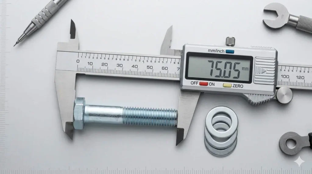
Why Digital Calipers are Mandatory for Diameter (vs. Tape Measures)
Digital calipers are the baseline tool for measuring hex bolt diameter because they deliver repeatable readings on the thread major diameter and shank.
Tape measures and rulers are fine for “rough length,” but they are not reliable for diameter and thread details. If you’re trying to match a bolt to a nut or tapped hole, you need a tool that can resolve small differences and avoid parallax error.
- Use calipers on the thread major diameter (OD) to identify the nominal size (M10, M12, 1/2″, etc.).
- Use calipers to verify WAF (head across flats) when tooling clearance is a constraint.
- For coated fasteners, measure in multiple locations to detect plating build-up or damage (a common cause of tight thread fit).
Engineering warning: A “correct” bolt size can still fail assembly if the bolt is coated and the mating nut is not matched for that coating. Hot-dip galvanized threads are intentionally oversized in some standards (fit changes are not a defect—they’re a requirement).
The table below summarizes why digital calipers reduce reading errors compared with analog tools:
| Feature | Digital Calipers | Analog Tools |
|---|---|---|
| Readout Type | Direct numeric readout | Manual interpretation |
| Parallax Error | Eliminated | Common |
| Measurement Repeatability | Higher | Operator-dependent |
| Data Logging | Possible (model-dependent) | Not practical |
| Field Use | Fast verification | Slower and less consistent |
Using Thread Pitch Gauges (Metric and Imperial Leaves)
Thread pitch gauges are essential for identifying the thread system and pitch on a hex bolt.
A pitch gauge leaf must seat cleanly into the thread form—no rocking, no daylight. This is the fastest way to confirm whether you’re holding metric coarse vs metric fine, or UNC vs UNF, before you attempt assembly.
- Use the gauge to confirm metric pitch (mm) or TPI—do not guess.
- Check thread form quality: rolled vs cut, damaged crests, flattened roots (these distort gauge readings).
- If the bolt is dirty, clean the first 3–5 threads. Debris changes the “feel” and produces false matches.
Tip: If the gauge “almost fits,” it usually means you are one pitch step off. Stop and verify—forcing a near-match is how cross-threading starts.
Standards note (fit matters): Metric thread tolerances and fits are commonly controlled using the ISO 965 system (for example 6g / 6H). If you are measuring to confirm interchangeability across suppliers, you must consider fit class—not only nominal size.
Measuring Length: The “Under-the-Head” Standard
The Bearing Surface Rule: Why Including the Head is a Critical Error
Always measure hex bolt length from the bearing surface under the head to the end of the bolt.
The head is not part of the clamped stack. The bearing surface is where clamp load enters the joint. Including the head is the fastest way to order the wrong length and lose thread engagement (or create bottoming in a tapped hole).
Field check: If your bolt “feels tight” but the joint still moves, verify that the bolt is not bottoming in the hole and that you actually have usable thread engagement after washers and runout.
 to the end")
Step-by-Step Measurement Guide (From Under Head to Blunt End)
Use this under-the-head procedure (this is the “orderable length” for hex bolts):
- Clean the bearing surface and the first few threads (remove burrs and packed debris).
- Set the caliper reference on the flat bearing surface under the head.
- Measure straight to the bolt end (do not follow chamfers or rounded tips).
- Record the value and compare it to the nearest standard length used in your drawing/PO.
Real-world mistakes that cause downtime:
- Measuring “over the head” and ordering bolts that bottom out in tapped holes.
- Ignoring washer thickness and thread runout (losing usable engagement).
- Ordering the right length but wrong pitch, then damaging the tapped hole during forced assembly.
Mini case (Problem → Analysis → Fix):
Problem: A maintenance team replaced bolts on a pump base, then the joint loosened during vibration.
Analysis: Bolts were too long and bottomed in the tapped holes; the “tight” feel was false preload.
Fix: Re-selected length based on under-the-head measurement + verified thread engagement depth; added torque/preload verification step in the work pack.
Exception Handling: Countersunk Screws (Total Length) vs. Hex Bolts
Measure total length for countersunk screws, but use under-the-head length for hex bolts.
Countersunk heads sit in the material and become part of the effective length. Hex heads sit above the surface, so only the shank length below the head controls fit and engagement.
| Fastener Type | Where to Measure Length |
|---|---|
| Hex Bolt | Under the head (bearing surface) to the end |
| Countersunk Screw | Total length, including the head |
For procurement consistency, define the governing standard and fit system on your PO (DIN/ISO/ANSI). If you are mixing suppliers or dealing with coated hardware, align thread tolerances (fit) and documentation to avoid “measures right but won’t assemble” failures.
Measuring Diameter vs. Width Across Flats (WAF)
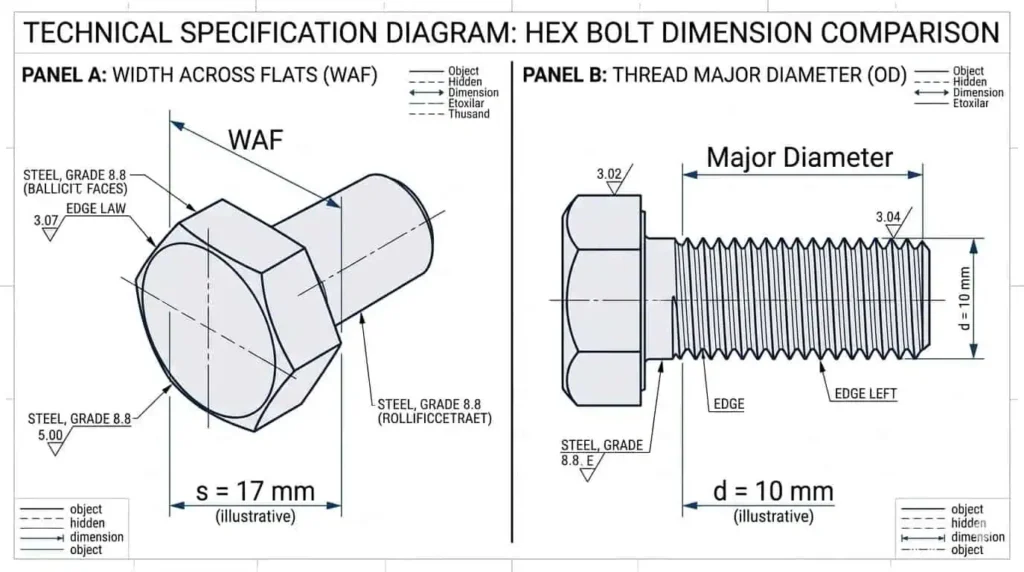
The Common Mistake: Confusing Wrench Size (WAF) with Thread Diameter
The most common ordering mistake is confusing head wrench size (WAF) with thread diameter.
WAF tells you the socket/wrench size. Thread diameter tells you the bolt size (M10, M12, 1/2″). Mixing the two creates the classic failure: “The wrench fits the head, but the bolt doesn’t fit the nut.”
- Thread diameter = compatibility with nut/tapped hole + strength basis (tensile stress area).
- WAF = tool fit + clearance constraints in tight assemblies.
- Width across corners = minimum clearance envelope (important in recesses).
Conversion trap: In mixed fleets, technicians often confuse M10 with 3/8″ because they “look close.” They are not interchangeable by pitch or diameter—verify with calipers and a pitch gauge every time.
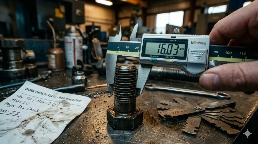
Measuring Major Diameter (OD) on the Threads
Measure the thread major diameter (OD) across the outermost thread crests using calipers.
Take at least two readings: near the first usable thread and mid-length. If the bolt is worn, the first threads lie to you—measure where threads are intact.
Engineering warning: Coatings change the OD. Electroplated zinc is relatively thin; hot-dip galvanizing is much thicker and often requires a different nut fit. If OD looks “oversize,” confirm whether the bolt is galvanized and whether the mating nut is specified for that condition.
The table below clarifies what each dimension means in purchasing and assembly control:
| Measurement Type | What It Controls |
|---|---|
| Major Diameter (OD) | Nominal size identification and basic compatibility check |
| Width Across Flats (WAF) | Tool selection and clearance planning |
| Width Across Corners | Minimum clearance envelope in pockets/recesses |
| Head Height | Head clearance; tool access and seating |
| Thread Length / Runout | Usable engagement after washers and stack-up |
| Max / Min Limits | Tolerance limits for interchangeability (fit system matters) |
| Reference Dimensions | Informational only; not always acceptance-controlled |
Standard Reference Table: Head Sizes vs. Nominal Diameters (Verify by Governing Standard)
Head dimensions (including WAF) are defined by the governing fastener standard set (DIN/ISO/ANSI/ASME).
If your site tooling is fixed (for example offshore tool control), treat WAF as an acceptance requirement. Do not assume that “ISO” and “DIN” always share the same wrench sizes for every diameter.
| Nominal Size (Inches) | Full-Size Body Diameter (E) | Width Across Flats (F) | Width Across Corners (G) | Head Height (H) | Radius of Fillet (R) | Thread Length (LT) |
|---|---|---|---|---|---|---|
| 1/4″ | 0.260 | 0.237 | 7/16″ | 0.438 | 0.425 | 0.505 |
| 5/16″ | 0.324 | 0.298 | 1/2″ | 0.500 | 0.484 | 0.577 |
| 3/8″ | 0.388 | 0.360 | 9/16″ | 0.562 | 0.544 | 0.650 |
| 1/2″ | 0.515 | 0.482 | 3/4″ | 0.750 | 0.725 | 0.866 |
| 1″ | 1.022 | 0.976 | 1-1/2″ | 1.500 | 1.450 | 1.732 |
| 2″ | 2.039 | 1.964 | 3″ | 3.000 | 2.9000 | 3.464 |
")
Practical tip: When a bolt “fits” but the socket doesn’t, you likely have a standard-mix issue (DIN vs ISO vs ANSI) or a supplier using a legacy wrench size. Verify WAF in incoming inspection if installation tooling is constrained.
Determining Thread Pitch and Count (TPI)
Metric Pitch (Distance in mm) vs. Imperial TPI (Threads Per Inch)
Metric thread pitch is measured as the distance between thread peaks in millimeters; imperial threads are identified by TPI (threads per inch).
Before you order, confirm whether the system is metric or inch. Then confirm whether it is coarse or fine. Two bolts can share the same diameter and still be incompatible by pitch.
- Metric example: M10×1.5 (coarse) vs M10×1.25 (fine).
- Imperial example: 1/2–13 (UNC) vs 1/2–20 (UNF).
- Assembly reality: A “near match” will start by hand for 1–2 turns, then seize. That is how threads get stripped.

The table below lists common TPI values and related geometry terms used in engineering calculations (stress area, pitch diameter). It’s a useful reference when you’re verifying a bolt you did not originally specify:
The table below shows common thread pitch values for hex bolts used in construction and manufacturing:
| Nominal Size and Threads Per In. | Basic Pitch Dia. | Section at Minor Dia. | Tensile Stress Area |
|---|---|---|---|
| 3⁄8 – 16 | 0.3344 | 0.0678 | 0.0775 |
| 7⁄16 – 14 | 0.3911 | 0.0933 | 0.1063 |
| 1⁄2 – 13 | 0.4500 | 0.1257 | 0.1419 |
| 9⁄16 – 12 | 0.5084 | 0.162 | 0.182 |
| 5⁄8 – 11 | 0.5660 | 0.202 | 0.226 |
| 3⁄4 – 10 | 0.6850 | 0.302 | 0.334 |
| 7⁄8 – 9 | 0.8028 | 0.419 | 0.462 |
| 1 – 8 | 0.9188 | 0.551 | 0.606 |
| 11⁄4 – 7 | 1.1572 | 0.890 | 0.969 |
")
Tip: If your facility uses both metric and imperial hardware, keep thread gauges for both systems in the tool crib. Mixed-thread mistakes are one of the highest-frequency, lowest-value failures in maintenance work.
How to Use a Thread Gauge to Identify Coarse vs. Fine Threads
A thread gauge is the fastest way to confirm pitch/TPI and prevent cross-threading.
Match the gauge leaf to the thread until it seats perfectly. If it rocks or shows daylight, it’s the wrong pitch. When a gauge is not available, you can count threads over a fixed length (1 inch for TPI), but that method is slower and more error-prone.
Steps to measure thread pitch or TPI on a hex bolt:
- Select a thread gauge leaf and place it against the bolt’s threads.
- Confirm full tooth engagement with no gaps.
- If no gauge is available: mark a 1-inch section and count peaks (TPI), or measure the distance across 10 threads and divide (metric pitch estimate).
Coarse threads tolerate dirt and damage better and are common in construction. Fine threads provide higher resistance to vibration loosening in some assemblies and allow finer preload adjustment, but they are less tolerant of damage. Use the thread system the equipment was designed for—don’t “upgrade to fine” without confirming the mating nut/tap and the drawing.
Mini case (Problem → Analysis → Fix):
Problem: A skid assembly seized during installation; the crew forced the bolt and stripped the nut.
Analysis: Diameter was correct, but pitch was wrong (fine thread bolt in coarse thread nut).
Fix: Implemented a “diameter + pitch” verification step using a pitch gauge in receiving inspection; added pitch to the PO line item.
Threads also fall into families like coarse (UNC) and fine (UNF). Knowing the family prevents mismatched replacement parts. Always verify the diameter, pitch/TPI, and thread system before ordering.
Summary: The 3-Step Verification Protocol
Use this 3-step verification protocol before you order—this is how experienced maintenance and procurement teams avoid repeat mistakes.
It is fast enough for the field and structured enough for audit-driven procurement.
- Measure the Length (Under Head):
Reference the bearing surface under the head. Measure to the end. Account for washers and engagement depth. - Check the Diameter (Major OD):
Measure across intact thread crests. Confirm the nominal size. Do not confuse WAF with diameter. - Identify Pitch / TPI:
Use a thread pitch gauge. Confirm coarse vs fine. Only then match to the nut or tapped hole.
Quick Reference Table: Where to Measure (Length, Dia, Pitch)
| Parameter | Common Range (Typical) | Where to Measure | Why It Matters |
|---|---|---|---|
| Length | Varies by standard and application | Under head (bearing surface) to end | Controls fit, engagement, and bottoming risk |
| Diameter | Varies by standard and application | Across thread major OD | Controls compatibility and strength basis |
| Thread Pitch | Coarse vs fine systems | Gauge match (or TPI count) | Prevents cross-threading and wrong parts |
| Head Width (WAF) | Standard-defined | Across flats on hex head | Controls tool fit and clearance |
CTA for controlled projects: If you don’t know the required preload method or friction conditions (nut factor / K-value), don’t guess torque. Ask for a joint-specific torque/preload table or consult an engineer—wrong preload is how joints loosen, leak, or fatigue crack.
Measuring a hex bolt correctly protects assembly reliability.
In factories and maintenance shops, three steps do the job every time: measure diameter with calipers, measure length under the head, and verify pitch with a gauge. If you need standard or custom fasteners with controlled documentation, Sunhy fasteners support batch tracking and dimensional verification when required by project QA.
Before you buy: confirm standard (DIN/ISO/ANSI), size, pitch/TPI, strength class (for steel bolts) or stainless class, coating, and any required traceability documents.
FAQ
How does someone measure hex bolt length correctly?
Measure from under the head (bearing surface) to the end of the bolt.
Do not include the head. This is the orderable length for hex bolts and controls engagement and bottoming risk in tapped holes.
What tool gives the most accurate bolt diameter measurement?
A digital caliper is the correct tool for diameter checks.
Measure across intact thread crests (major diameter). If the bolt is coated or damaged, measure more than one location and verify against the intended fit system.
Why do stainless bolts sometimes seize (galling) during installation?
Stainless threads can gall under high friction and speed, especially without lubrication.
Use an approved anti-seize where the procedure allows, avoid high-speed dry installation, and apply controlled tightening. If galling repeats, review stainless grade/class and the assembly method together.
Why is it important not to confuse wrench size with bolt diameter?
WAF (wrench size) and thread diameter are different measurements.
WAF controls tool fit. Diameter controls compatibility and strength. Mixing them up is how the “wrong bolt size” gets ordered even when the head looks right.
What should someone do before ordering hex bolts?
Verify length, diameter, and pitch—then confirm standard, strength class, and coating.
If you’re unsure about fit class or thread tolerances, start with the technical guides and measurement references here: technical guides. For critical assemblies, require inspection records and traceability documentation on the PO.