Oxygen Sensor Technical Guide
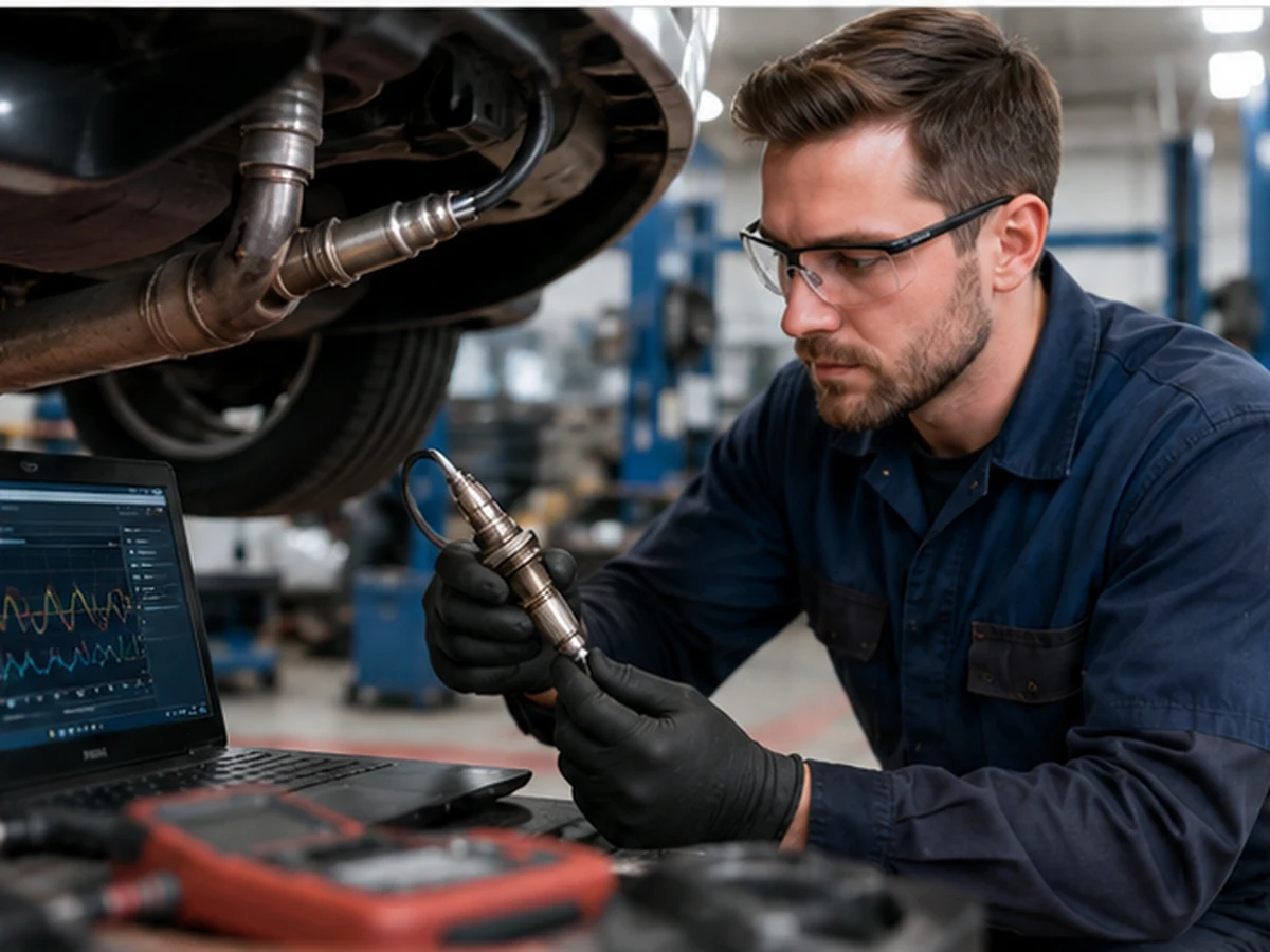
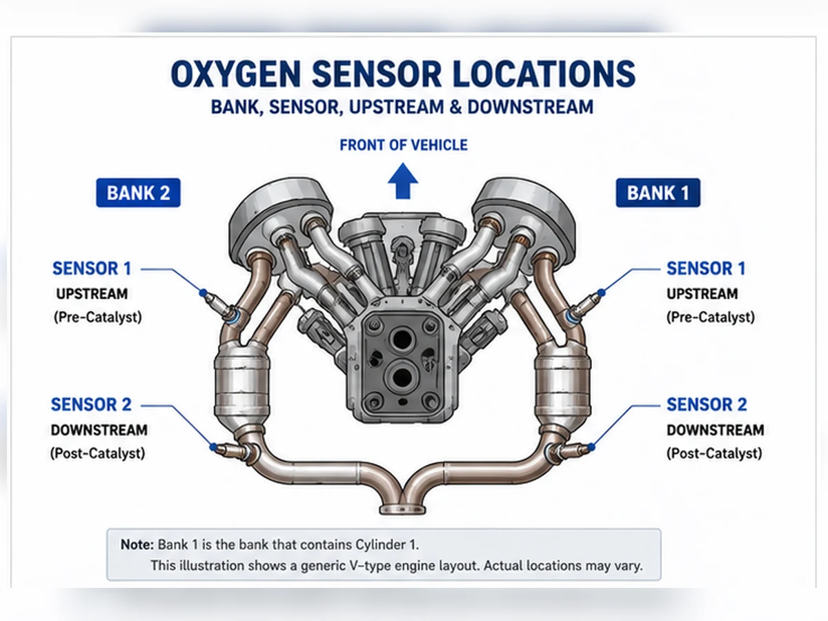
Bank 1 Sensor 1 is commonly upstream and Bank 1 Sensor 2 downstream, but cylinder location and the vehicle exhaust diagram must confirm the position.
Quick answer
Bank 1 Sensor 1 is generally the oxygen or air-fuel-ratio sensor before the catalytic converter on the bank containing cylinder 1. Bank 1 Sensor 2 is generally the sensor after that catalyst. Sensor 1 often supports fuel-control feedback, while Sensor 2 commonly supports catalyst monitoring. Confirm the engine’s cylinder numbering and exhaust layout before diagnosis or ordering.
Decode the name in the correct order
This method is more reliable than “left,” “right,” “front” or “rear,” which can change meaning with longitudinal and transverse engine installation.
Bank 1 Sensor 1 and Sensor 2 compared
| Detail | Bank 1 Sensor 1 | Bank 1 Sensor 2 |
|---|---|---|
| Common location | Upstream / pre-catalyst | Downstream / post-catalyst |
| Common role | Mixture feedback | Catalyst monitoring |
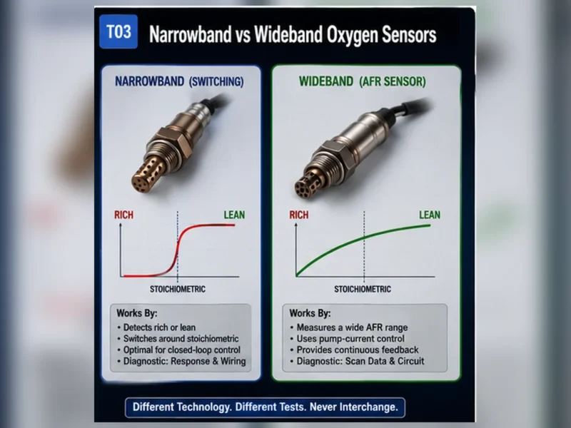
| Technology | May be narrowband or wideband/A/F | Often narrowband, but application data controls |
| Common buying error | Wrong bank, technology or connector | Wrong cable length, routing or post-cat position |
How the position appears in fault codes
A code description may name Bank 1 Sensor 1 or Bank 1 Sensor 2, but that still identifies a circuit or monitored condition rather than a confirmed failed part. Test wiring, heater supply, connector condition and signal behavior. For mixture or catalyst codes, inspect engine and exhaust causes as well.
Why the two sensors may not interchange
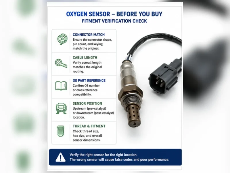
They can differ in sensor technology, calibration, protective shield, connector keying, cable length and routing clips even when the threads look identical. Match the OE number and verified application for the exact position. Never extend or force a direct-fit harness to make the wrong sensor reach.
Pre-order verification record
- VIN or complete year/make/model/engine
- Market and emissions package
- Cylinder 1 and Bank 1 location
- Sensor 1 or Sensor 2 relative to the catalyst
- OE reference and current cross-reference
- Connector face, keying, pins, lead length and clips
Find Bank 1 before looking for a sensor number
Bank 1 is the cylinder bank containing cylinder 1. The cylinder-1 side depends on the engine design and installation, so Bank 1 is not universally the driver side, passenger side, front or rear. Use the manufacturer cylinder-numbering diagram for the exact engine. On an inline engine there is usually only one bank, but the service terminology still controls.
| Shortcut | Why it fails | Reliable evidence |
|---|---|---|
| Bank 1 is always driver side | Cylinder numbering differs | Engine service diagram |
| Front bank means Bank 1 | Transverse orientation varies | Cylinder 1 location |
| One code photo identifies the connector | Harness routing can cross the engine | Wiring and exhaust diagrams |
| Inline engine has Bank 2 | Generic scan labels may be unsupported | Vehicle-specific data support |
Trace exhaust flow to identify Sensor 1 and Sensor 2
Bank 1 Sensor 1
Sensor 1 is commonly the oxygen or A/F sensor before the relevant catalyst on Bank 1. It commonly supports mixture feedback after enable conditions are met. Its technology may be narrowband, wideband/A/F or another specified design.
Bank 1 Sensor 2
Sensor 2 is commonly after the monitored catalyst on Bank 1 and supports catalyst-system monitoring. Some layouts use additional sensors or manufacturer-specific naming. Confirm the physical exhaust order instead of counting connectors from the engine outward without a diagram.
Why “front” and “rear” are ambiguous
On a transverse engine, “front” may describe the vehicle side, engine bank or upstream position. A parts listing that says front/rear without Bank/Sensor and engine context is incomplete.
Compare their common roles and evidence
| Decision item | Bank 1 Sensor 1 | Bank 1 Sensor 2 |
|---|---|---|
| Common location | Before Bank 1 catalyst | After Bank 1 catalyst |
| Common role | Mixture feedback | Catalyst monitoring |
| Data interpretation | Technology-specific rich/lean or wide-range response | Compared with catalyst and upstream behavior |
| Typical ordering risk | Wrong technology or bank | Wrong lead length, route or post-cat position |
How position appears in DTC descriptions
A code naming Bank 1 Sensor 1 or Bank 1 Sensor 2 narrows the circuit or monitor path. It does not prove the sensing element failed. A heater code needs supply, ground/control, connector and element checks; a low/high or response code needs circuit, operating-state, leak and mixture evidence. P0420 concerns catalyst-system efficiency and is not an automatic B1S2 order.
| Code wording | Position question | Diagnostic question |
|---|---|---|
| B1S1 heater | Correct pre-cat Bank 1 connector? | Is power/control delivered under specified conditions? |
| B1S1 low/high | Correct upstream circuit? | Electrical limit or real mixture? |
| B1S2 no activity | Correct post-cat connector? | Warm, powered, connected and supported PID? |
| P0420 Bank 1 | Which catalyst path is monitored? | Engine, leak, sensors or catalyst condition? |
Trace connectors without creating a new fault
Allow the exhaust to cool and use approved support equipment. Follow each sensor cable to its connector without pulling the wires. Note clips, heat sleeves and crossing routes. Do not disconnect several identical-looking connectors without labeling them; reconnecting sensors to the wrong harness branch can create misleading codes and unsafe routing.
Match live data to the physical sensor
Confirm the scan-tool PID, units and supported technology. Observe Bank 1 Sensor 1 under valid closed-loop conditions and Bank 1 Sensor 2 in the catalyst-monitor context defined by service information. Do not compare a wideband current parameter with a narrowband voltage rule. If unplugging a connector is part of an official test, follow that procedure and avoid using disconnection as an improvised identification method.
Why Sensor 1 and Sensor 2 may not interchange
They can share thread size yet differ in technology, heater, calibration, shield, connector keying, pin assignment, cable length and clips. Match OE reference, vehicle/engine/market, exact position and current application record. Do not cut, extend or force a direct-fit harness to make a sensor intended for another position reach.
| Fitment check | Required evidence | Reject when |
|---|---|---|
| OE reference | Current mapping for B1S1 or B1S2 | Listing gives model only |
| Technology | Specified sensing/control design | Wire count is the only match |
| Connector | Keying and terminal assignment | Plug requires force |
| Lead routing | Length, sleeve and clips | Cable contacts heat/movement |
Composite scenario: the correct bank is on the unexpected side
Composite diagnostic scenario: a repair begins at the passenger-side sensor because a generic forum calls that side Bank 1. The engine diagram shows cylinder 1 on the opposite bank. Relocating the test to the code-named circuit prevents replacement of a functioning sensor. This is a composite teaching pattern, not a Sunhyings vehicle or fitment claim.
Create a position verification record
Save the engine/cylinder diagram, code description, exhaust-path sketch, connector photo, OE number and measured cable route. After repair, confirm the correct PID responds, the harness is clipped away from heat and the applicable monitor completes. Position certainty should be established before diagnosis and again before ordering.
A repeatable Bank 1 identification workflow
Step 1: identify the exact engine
Record VIN-derived engine information, engine code where available, sales market and emissions label. Do not use a diagram for another displacement or model year merely because the engine cover looks similar.
Step 2: locate cylinder 1
Use manufacturer service information to find cylinder 1 and the cylinder bank. Mark Bank 1 on a copy of the diagram. If the engine is inline, confirm that a Bank 2 label is not a generic unsupported scan-tool item.
Step 3: map catalysts and sensor order
Trace exhaust flow from Bank 1. Mark the first sensing position before the relevant catalyst and the monitored position after it. Account for close-coupled catalysts and branches that can be hidden by shields.
Step 4: reconcile wiring and physical routing
Follow the diagram from the named sensor to its connector and control-module circuit. Harnesses can cross the engine or join a common bracket, so proximity to a bank does not prove electrical identity.
| Workflow output | Record | Reason |
|---|---|---|
| Engine identity | Engine code/VIN context and market | Selects correct diagrams |
| Bank identity | Cylinder 1 side | Eliminates side shortcuts |
| Sensor identity | Pre/post catalyst order | Separates Sensor 1 and Sensor 2 |
| Circuit identity | Connector and pin path | Ensures testing reaches the named circuit |
If service information and physical observation still conflict, stop and escalate the identification rather than choosing a side by convention. Prior repairs may have rerouted connectors or installed the wrong part. Record the conflict, connector labels, wire colors only as observed facts, and exhaust context so the next reviewer can resolve the circuit without repeating assumptions. Do not reconnect crossed harness branches simply to see which code appears; use the diagram and continuity procedure, then preserve the verified mapping with the repair record.
A repeatable method to locate Bank 1
Bank 1 is the side or exhaust path containing cylinder 1. Sensor 1 is normally the sensor before the catalyst for that bank; Sensor 2 is normally the sensor after the monitored catalyst. The words “normally” and “for that bank” matter. Use exact engine and exhaust information when layouts include merged pipes, multiple catalysts or more than two sensors.
- Confirm the exact engine, not only displacement or model badge.
- Find cylinder numbering from verified service information.
- Identify the cylinder 1 side or exhaust runner.
- Trace exhaust flow through the relevant catalyst.
- Map Sensor 1 and Sensor 2 to physical connectors and scan-data labels.
- Photograph or record the route before disconnecting anything.
| Shortcut | Why it fails | Reliable replacement |
|---|---|---|
| Bank 1 is always driver’s side | Engine orientation and cylinder numbering vary | Locate cylinder 1 from service information |
| Sensor 1 is always easiest to see from above | Packaging can place pre-catalyst sensor behind engine | Trace exhaust flow before the catalyst |
| Sensor 2 means the second connector found | Harness order does not define exhaust position | Locate sensor after the monitored catalyst |
| P013x always means Bank 1 | Code suffix and family must be read completely | Use full description and exact DTC mapping |
| Front/rear equals Sensor 1/2 | Vehicle direction is not catalyst relationship | Use pre-cat/post-cat identity |
How engine and exhaust layout change the map
| Configuration | Bank meaning | Sensor numbering concern | Data needed |
|---|---|---|---|
| Inline engine | Usually one cylinder bank | May still have multiple sensors/catalysts | Exact exhaust diagram and sensor count |
| Longitudinal V engine | Left/right banks by cylinder numbering | Physical side cannot be generalized across makes | Engine code and cylinder layout |
| Transverse V engine | One bank toward firewall, one toward radiator | Front bank is not universally Bank 1 | Cylinder 1 location and installation orientation |
| Opposed engine | Separate cylinder sides | Common side assumptions remain unsafe | Manufacturer cylinder numbering |
| Merged exhaust | Bank-specific upstream paths may merge | Downstream monitoring can become shared | Complete catalyst and pipe layout |
| Multiple catalyst stages | Bank identity remains tied to cylinders | Sensor 2/3 designation needs exact diagram | Service component location and DTC definition |
Use the code to identify a test path, then verify the physical sensor
| Example code group | Named area | Physical confirmation | Test boundary |
|---|---|---|---|
| P0130-P0135 | Commonly Bank 1 Sensor 1 signal/response/heater families | Pre-catalyst sensor on cylinder 1 bank | Full code description and service logic control |
| P0136-P0141 | Commonly Bank 1 Sensor 2 signal/response/heater families | Post-catalyst sensor for Bank 1 path | Not automatic catalyst or sensor replacement |
| P0150-P0155 | Commonly Bank 2 Sensor 1 families | Pre-catalyst sensor on opposite bank | Actual mixture and circuit causes still apply |
| P0156-P0161 | Commonly Bank 2 Sensor 2 families | Post-catalyst sensor for Bank 2 path | Rear signal needs monitor context |
| P0420 | Catalyst efficiency below threshold, Bank 1 | Entire Bank 1 engine/exhaust/sensor/catalyst path | Does not order B1S2 |
| P0430 | Catalyst efficiency below threshold, Bank 2 | Entire Bank 2 path | Does not order B2S2 |
Map scan data to the connector before judging a waveform
Use a service diagram and non-destructive confirmation method. Compare bank-specific response to a controlled operating change where the procedure allows. If disconnecting or manipulating a circuit is part of the OEM test, follow its precautions. Do not create a short, pierce insulation without repair or apply a narrowband voltage expectation to a wideband circuit.
| Evidence | Confirms | Does not confirm alone |
|---|---|---|
| Cylinder numbering diagram | Which side contains cylinder 1 | Sensor connector route |
| Exhaust component diagram | Sensor position relative to catalyst | Correct sellable part number |
| Wiring diagram | Circuit, pins, shared power and control | Physical bung without location view |
| Scan-data label | Module-reported bank/sensor channel | That the harness is connected to intended sensor |
| OE/application catalog | Candidate part mapping | Diagnosis or connector correctness after repair work |
B1S1 and B1S2 are not interchangeable labels
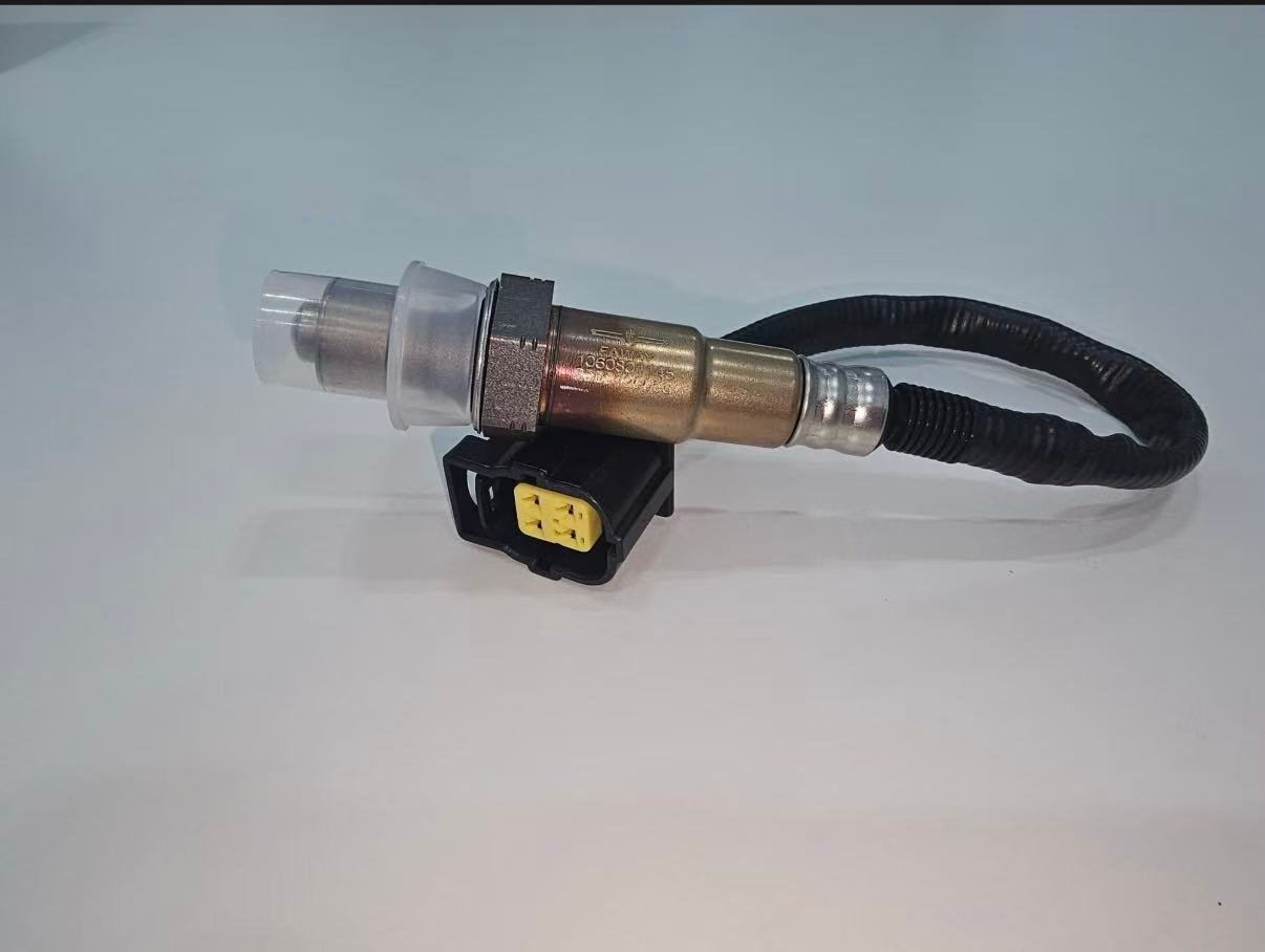
The two positions can use different technologies, heaters, shields, connectors, lead lengths and calibration. Some catalogs legitimately use one part in multiple positions, but that conclusion must come from current controlled application data. Never make a direct-fit sensor reach by cutting or extending its harness.
| Selection input | B1S1 requirement | B1S2 requirement |
|---|---|---|
| Function | Mixture-feedback technology for exact application | Post-catalyst monitoring technology for exact application |
| OE mapping | Current mapping to Bank 1 Sensor 1 | Current mapping to Bank 1 Sensor 2 |
| Connector | Correct key, pins and circuit | Correct key, pins and circuit |
| Lead route | Reaches upstream connector with approved clips | Reaches downstream connector without heat/motion conflict |
| Verification | Technology-correct mixture response | Rear response and catalyst-monitor context |
Composite case: driver-side shorthand selected Bank 2
Composite parts scenario: a request says “driver-side upstream” and supplies a Bank 1 code. The parts specialist pauses because the engine’s cylinder 1 side has not been established. Service information shows that the driver’s side is Bank 2 for the exact engine installation. The request is corrected to the verified Bank/Sensor identity before quotation.
This scenario demonstrates an identification control and is not a claim about a named vehicle or Sunhyings order. The correct side must always come from exact application evidence.
Composite case: one downstream sensor monitors a merged path
Composite diagnostic scenario: a technician expects four sensors because the engine has two banks. The service diagram shows two bank-specific upstream sensors but one downstream sensor after the pipes merge. Counting banks alone would have created a nonexistent B2S2 order. The actual sensor count and monitor labels are verified from the exhaust diagram and scan data.
The example is deliberately generic. It proves the method, not a universal three-sensor rule. Always document engine, exhaust configuration and emissions market.
Final Bank/Sensor identification record
- Exact VIN/YMME, engine code where relevant and market/emissions configuration
- Verified cylinder 1 source and resulting Bank 1 physical side
- Exhaust-flow diagram and position relative to catalyst
- Scan-data/DTC label matched to physical connector
- OE reference, technology, connector, pin count, lead and clips
- Before/after test evidence for the named circuit
Conduct a physical survey without guessing from visibility
With the exhaust cool and the vehicle safely supported where underbody access is required, follow each manifold or exhaust branch toward its catalyst. Note each sensor bung, connector branch and harness clip. Use a mirror or camera where direct visibility is limited. Do not reach around hot exhaust or rely on the first sensor visible from above.
| Survey item | Record | Reason |
|---|---|---|
| Engine orientation | Longitudinal/transverse and cylinder-bank diagram | Vehicle left/right does not define Bank 1 |
| Cylinder 1 location | Service source and physical side | Defines Bank 1 |
| Exhaust path | Manifold, merge points and catalyst stages | Defines Sensor position |
| Connector branches | Connector IDs, route and retention | Prevents crossed or wrong-branch testing |
| Existing labels | Readable OE/part marks and orientation | Supports but does not replace controlled fitment data |
| Damage evidence | Heat, chafe, water, impact and prior repair | Can explain circuit symptoms |
Use bank-to-bank comparison carefully
On an engine with separate bank feedback, comparing fuel trims and upstream response can help distinguish a shared condition from a bank-specific one. A difference can point toward a localized intake leak, injector, ignition, compression, exhaust leak, wiring or sensor concern. It does not by itself name the failed part. Loads, temperatures and control states must be comparable.
| Observed pattern | Possible direction | Required confirmation |
|---|---|---|
| Both banks corrected similarly | Shared air/fuel/measurement condition | Common intake, fuel, airflow and temperature inputs |
| Bank 1 differs mainly at idle | Bank-specific unmetered air or exhaust leak | Trim versus airflow and leak testing |
| Bank 1 differs at idle and load | Fuel delivery, sensor/circuit or mechanical difference | Injector, ignition, compression and response evidence |
| One bank heater is inactive | Bank-specific sensor or circuit fault | Loaded power/control test and shared-circuit review |
| Rear bank signals differ | Catalyst-path, leak or sensor difference | Upstream validity and exact monitor procedure |
Installation boundary after Bank/Sensor identification
Correct identity does not remove installation risk. Allow the exhaust to cool, support the vehicle correctly and follow the exact service access procedure. Apply only specified torque and thread treatment. Restore the connector lock, heat shields and every routing clip. Do not cut a direct-fit harness or move a sensor to a different bung to make a part fit.
After installation, prove that the scan-data channel now corresponds to the physical sensor and that heater and response tests pass. Complete the applicable monitor legally. Clearing the DTC or seeing the warning lamp turn off before the monitor runs is not full verification.
Wrong-bank and wrong-position return analysis
| Complaint | Evidence to collect | Possible categories |
|---|---|---|
| Connector will not engage | Connector faces, pins, labels, vehicle and position | Wrong part, wrong position, catalog or packing error |
| Lead does not reach | Full route, clip points, old/new length and part identity | Wrong bank/position, wrong part or incorrect routing |
| Code remains after replacement | Before/after codes, circuit and response tests | Wrong sensor changed, unresolved vehicle fault or part issue |
| Opposite bank data changed | Connector map and harness routing | Crossed connectors or scan/physical mapping error |
| Physical heat damage | Installed clearance, shields, clips and movement | Routing, application length or missing protection |
RFQ data for a bank-specific oxygen sensor
For sourcing, send the OE reference candidate, complete vehicle/engine/emissions identity, Bank and Sensor designation, cylinder 1 source, connector and old-part photos, lead/clip measurements, quantity, market and approval requirements. Sunhyings can review the submitted scope for sourcing feasibility. Fitment, stock, price, MOQ, lead time and certification remain unconfirmed until part-level evidence is matched.
Resolve conflicting position information with a source hierarchy
Position conflicts are common when a generic code reader, marketplace listing, forum photo and workshop shorthand use different naming. Start with exact vehicle service information and controlled application data for the VIN/configuration. Use the removed part and physical layout as corroborating evidence. A forum or unlabeled image can suggest what to check, but it should not control a bank-specific order.
| Source | Useful for | Control required | Conflict action |
|---|---|---|---|
| OEM service information | Cylinder numbering, component location, wiring and test method | Exact model/engine/market and current document | Confirm applicability and supersession |
| Controlled parts catalog | OE and aftermarket candidate mapping | Revision, source and Bank/Sensor field | Hold row if service/physical evidence differs |
| VIN/build/emissions records | Vehicle configuration and breakpoints | Complete readable identity | Resolve missing or inconsistent build data |
| Removed-part marking | Corroborating identity from installed part | Readable number and known original position | Check whether prior repair installed wrong part |
| Physical connector/layout | Routing and interface comparison | Photos showing context, not cropped connector only | Do not force fit; reconcile with records |
| Search/forum content | Generating questions to verify | No authority for final fitment | Replace with controlled source |
Composite case: scan labels were correct but connectors were crossed
Composite workshop scenario: after an engine repair, Bank 1 and Bank 2 upstream data appear reversed during a controlled mixture comparison. Cylinder numbering and scan labels are correct. A harness survey finds two nearby connectors crossed during reassembly. Restoring the documented connector routing aligns physical response with the expected bank channels.
The case illustrates why a code reader alone cannot prove which physical sensor is connected. It also shows why changing both sensors would have preserved the wiring error. This is a composite pattern, not a Sunhyings customer case or a statement about any vehicle brand.
Post-repair proof for Bank 1 Sensor 1 or Sensor 2
Verify part number, connector lock, clip positions, heat clearance and exhaust sealing. For Sensor 1, document technology-correct response and plausible bank fuel control under valid conditions. For Sensor 2, document circuit/response and the applicable catalyst-monitor context. Compare the result with the original fault; do not claim success solely because codes were cleared.
If the opposite bank or another sensor now sets a code, review shared supplies, connector mapping and the complete system before assuming a second independent failure. Preserve permanent codes and readiness information according to the vehicle and regulatory procedure.
A defensible final record names who verified the cylinder 1 source, which document revision was used, which physical connector was serviced and which data channel was checked afterward. This level of traceability is especially important when a workshop, distributor and supplier handle different parts of the claim.
Do not publish a Bank 1 side rule for an entire brand. Even within one make, engine families and installation orientations can differ. A brand-level article may teach the identification method, but only part-level vehicle evidence can support a fitment claim.
When reliable cylinder numbering or exhaust-layout data is unavailable, mark the position decision DATA NOT AVAILABLE and stop the order. Guessing a side creates avoidable installation, return and emissions-system risk. Request the VIN, engine details or an authoritative diagram rather than converting uncertainty into an implied fit.
For B2 or Sensor 3 applications, use the same method rather than extending a B1S1/B1S2 rule. Bank remains tied to cylinder numbering, while sensor number must be traced through the exact catalyst layout. This page’s primary comparison stays B1S1 versus B1S2, but the evidence discipline applies to every additional monitored position.
Prepare a fitment or sourcing request
Send the OE number, year/make/model, engine or VIN details, market and emissions package, exact bank/sensor position, connector and old-part photos, quantity and any packaging or approval requirements. Sunhyings will review the supplied data for capability and sourcing feasibility; fitment is not confirmed until application evidence is matched.
Frequently asked questions
Is Bank 1 Sensor 1 upstream?
It is generally the upstream or pre-catalyst sensor on the bank containing cylinder 1.
Is Bank 1 Sensor 2 downstream?
It is generally the downstream or post-catalyst sensor on Bank 1.
Is Bank 1 on the driver side?
Not universally. Bank 1 is defined by cylinder 1, and its physical side depends on the engine.
Can Sensor 1 and Sensor 2 use the same part?
Only when verified application data lists the exact part for both positions. Similar threads or plugs are not enough.
Does a Bank 1 Sensor 2 code mean replace that sensor?
No. It identifies the circuit or monitor to diagnose; wiring, exhaust and catalyst conditions may also be involved.