








Guida tecnica al sensore di ossigeno
Il sensore 1 del banco 1 è solitamente a monte e il sensore 2 del banco 1 a valle, ma la posizione dei cilindri e lo schema dello scarico del veicolo devono confermare la posizione.
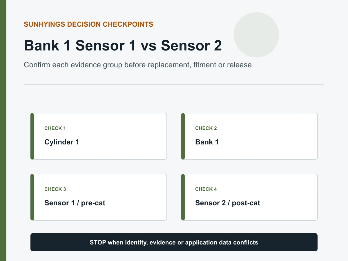
Risposta rapida
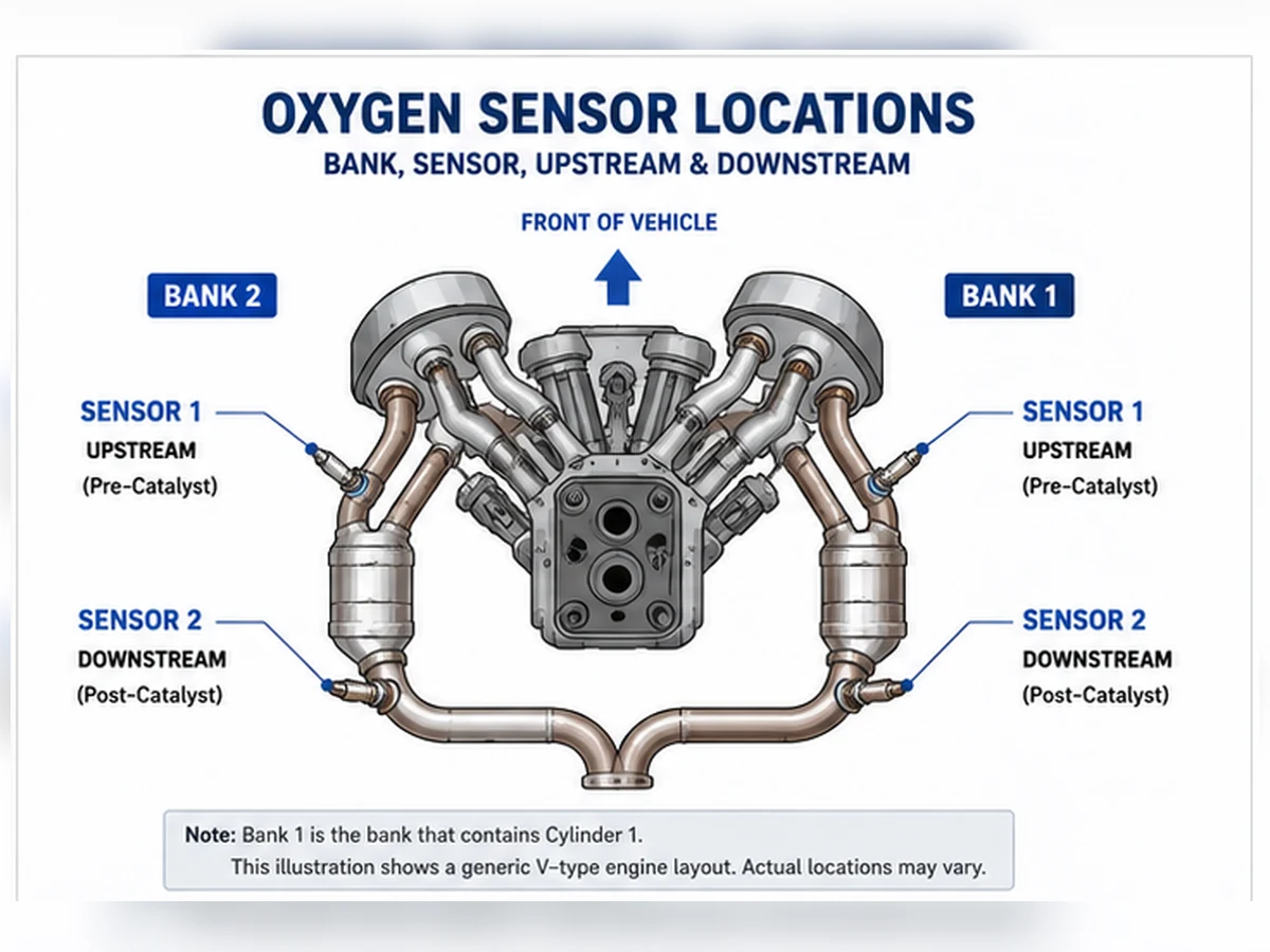
Banca 1 Sensore 1 è generalmente il sensore di ossigeno o rapporto aria-carburante prima del catalizzatore sulla banca contenente il cilindro 1. Banca 1 Sensore 2 è generalmente il sensore dopo quel catalizzatore. Il Sensore 1 spesso supporta il feedback di controllo del carburante, mentre il Sensore 2 supporta comunemente il monitoraggio del catalizzatore. Confermare la numerazione dei cilindri del motore e la disposizione dello scarico prima della diagnosi o dell'ordine.
Decodificare il nome nell'ordine corretto
Questo metodo è più affidabile di “sinistra”, “destra”, “anteriore” o “posteriore”, che possono cambiare significato con l'installazione longitudinale e trasversale del motore.
Sensore 1 e Sensore 2 del banco 1 a confronto
| Dettaglio | Banco 1 Sensore 1 | Bancata 1 Sensore 2 |
|---|---|---|
| Posizione comune | A monte / pre-catalizzatore | A valle / post-catalizzatore |
| Ruolo comune | Feedback della miscela | Monitoraggio del catalizzatore |
| Tecnologia | Può essere a banda stretta o larga/A/F | Spesso a banda stretta, ma i dati applicativi controllano |
| Errore comune di acquisto | Banca, tecnologia o connettore sbagliati | Lunghezza del cavo, instradamento o posizione post-cat sbagliati |
Come appare la posizione nei codici di guasto
Una descrizione del codice può nominare Bank 1 Sensor 1 o Bank 1 Sensor 2, ma ciò identifica comunque un circuito o una condizione monitorata piuttosto che un componente guasto confermato. Testare il cablaggio, l'alimentazione del riscaldatore, le condizioni del connettore e il comportamento del segnale. Per i codici di miscela o catalizzatore, ispezionare anche le cause relative al motore e allo scarico.
Perché i due sensori potrebbero non essere intercambiabili
Possono differire per tecnologia del sensore, calibrazione, schermo protettivo, codifica del connettore, lunghezza del cavo e clip di instradamento anche quando le filettature sembrano identiche. Abbina il numero OE e l'applicazione verificata per la posizione esatta. Non estendere mai né forzare un cablaggio diretto per far arrivare il sensore sbagliato.
Registro di verifica del preordine
- VIN o anno/marca/modello/motore completi
- Mercato e pacchetto emissioni
- Posizione del cilindro 1 e della bancata 1
- Sensore 1 o Sensore 2 rispetto al catalizzatore
- Riferimento OE e cross-reference attuale
- Faccia del connettore, codifica, pin, lunghezza del cavo e clip
Individuare il banco 1 prima di cercare un numero di sensore
La bancata 1 è la bancata di cilindri che contiene il cilindro 1. Il lato del cilindro 1 dipende dal progetto e dall'installazione del motore, quindi la bancata 1 non è universalmente il lato guida, lato passeggero, anteriore o posteriore. Utilizza lo schema di numerazione dei cilindri del produttore per il motore esatto. Su un motore in linea di solito c'è una sola bancata, ma la terminologia di servizio è comunque determinante.
| Scorciatoia | Perché fallisce | Prova affidabile |
|---|---|---|
| La bancata 1 è sempre lato guida | La numerazione dei cilindri differisce | Schema di manutenzione del motore |
| Bancata anteriore significa bancata 1 | L'orientamento trasversale varia | Posizione del cilindro 1 |
| Una foto del codice identifica il connettore | Il percorso del cablaggio può attraversare il motore | Schemi di cablaggio e scarico |
| Il motore in linea ha il Banco 2 | Le etichette di scansione generiche potrebbero non essere supportate | Supporto dati specifici del veicolo |
Tracciare il flusso di scarico per identificare il Sensore 1 e il Sensore 2
Banco 1 Sensore 1
Il Sensore 1 è comunemente il sensore di ossigeno o A/F prima del catalizzatore pertinente sul Banco 1. Supporta generalmente il feedback della miscela dopo che le condizioni di abilitazione sono soddisfatte. La sua tecnologia può essere a banda stretta, a banda larga/A/F o altro progetto specificato.
Bancata 1 Sensore 2
Il Sensore 2 è comunemente dopo il catalizzatore monitorato sul Banco 1 e supporta il monitoraggio del sistema catalizzatore. Alcune configurazioni utilizzano sensori aggiuntivi o denominazioni specifiche del produttore. Confermare l'ordine fisico dello scarico invece di contare i connettori dal motore verso l'esterno senza uno schema.
Perché “anteriore” e “posteriore” sono ambigui
Su un motore trasversale, “anteriore” può descrivere il lato del veicolo, la bancata del motore o la posizione a monte. Un elenco di parti che indica anteriore/posteriore senza il contesto di bancata/sensore e motore è incompleto.
Confrontare i loro ruoli comuni e le evidenze
| Elemento decisionale | Banco 1 Sensore 1 | Bancata 1 Sensore 2 |
|---|---|---|
| Posizione comune | Prima del catalizzatore della bancata 1 | Dopo il catalizzatore della bancata 1 |
| Ruolo comune | Feedback della miscela | Monitoraggio del catalizzatore |
| Interpretazione dei dati | Risposta ricca/magra o a banda larga specifica della tecnologia | Confrontato con il comportamento del catalizzatore e a monte |
| Rischio tipico di ordinazione | Tecnologia o banca errati | Lunghezza, percorso o posizione post-cat errati |
Come appare la posizione nelle descrizioni DTC
Un codice che identifica il sensore Bank 1 Sensor 1 o Bank 1 Sensor 2 restringe il circuito o il percorso di monitoraggio. Non dimostra che l'elemento sensore si è guastato. Un codice del riscaldatore richiede controlli di alimentazione, massa/controllo, connettore ed elemento; un codice di segnale basso/alto o di risposta richiede evidenze di circuito, stato operativo, perdite e miscela. P0420 riguarda l'efficienza del sistema catalizzatore e non è un ordine automatico di B1S2.
| Formulazione del codice | Domanda sulla posizione | Domanda diagnostica |
|---|---|---|
| Riscaldatore B1S1 | Connettore pre-cat Bank 1 corretto? | Alimentazione/controllo erogati nelle condizioni specificate? |
| B1S1 basso/alto | Circuito a monte corretto? | Limite elettrico o miscela reale? |
| B1S2 nessuna attività | Connettore post-cat corretto? | PID caldo, alimentato, connesso e supportato? |
| P0420 Banco 1 | Quale percorso del catalizzatore viene monitorato? | Motore, perdite, sensori o condizioni del catalizzatore? |
Tracciare i connettori senza creare un nuovo guasto
Lasciare raffreddare lo scarico e utilizzare attrezzature di supporto approvate. Seguire il cavo di ciascun sensore fino al suo connettore senza tirare i fili. Annotare clip, guaine termiche e percorsi incrociati. Non scollegare più connettori identici senza etichettarli; ricollegare i sensori al ramo sbagliato del cablaggio può creare codici fuorvianti e instradamenti non sicuri.
Abbinare i dati live al sensore fisico
Confermare il PID dello strumento di scansione, le unità e la tecnologia supportata. Osservare il sensore Bank 1 Sensor 1 in condizioni valide a ciclo chiuso e il sensore Bank 1 Sensor 2 nel contesto del monitoraggio del catalizzatore definito dalle informazioni di servizio. Non confrontare un parametro di corrente a banda larga con una regola di tensione a banda stretta. Se scollegare un connettore fa parte di un test ufficiale, seguire tale procedura ed evitare di utilizzare lo scollegamento come metodo di identificazione improvvisato.
Perché il Sensore 1 e il Sensore 2 potrebbero non essere intercambiabili
Possono condividere la dimensione della filettatura ma differire per tecnologia, riscaldatore, calibrazione, schermatura, codifica del connettore, assegnazione dei pin, lunghezza del cavo e clip. Abbinare il riferimento OE, veicolo/motore/mercato, posizione esatta e record di applicazione corrente. Non tagliare, estendere o forzare un cablaggio direct-fit per far arrivare un sensore destinato a un'altra posizione.
| Verifica di montaggio | Prova richiesta | Rifiutare quando |
|---|---|---|
| Riferimento OE | Mappatura corrente per B1S1 o B1S2 | L'elenco fornisce solo il modello |
| Tecnologia | Progetto di rilevamento/controllo specificato | Il numero di fili è l'unica corrispondenza |
| Connettore | Codifica e assegnazione dei terminali | La spina richiede forza |
| Percorso dei cavi | Lunghezza, guaina e clip | Contatti del cavo calore/movimento |
Scenario composito: la bancata corretta si trova sul lato inaspettato
Scenario diagnostico composito: una riparazione inizia dal sensore lato passeggero perché un forum generico chiama quel lato Banca 1. Lo schema del motore mostra il cilindro 1 sulla banca opposta. Spostare il test sul circuito indicato dal codice evita la sostituzione di un sensore funzionante. Questo è un modello didattico composito, non un veicolo Sunhyings o un'affermazione di adattamento.
Creare un record di verifica della posizione
Salvare lo schema motore/cilindri, la descrizione del codice, lo schema del percorso di scarico, la foto del connettore, il numero OE e il percorso misurato del cavo. Dopo la riparazione, confermare che il PID corretto risponda, che il cablaggio sia fissato lontano dal calore e che il monitor applicabile si completi. La certezza della posizione dovrebbe essere stabilita prima della diagnosi e di nuovo prima dell'ordine.
Un flusso di lavoro ripetibile per l'identificazione della Bancata 1
Fase 1: identificare il motore esatto
Registrare le informazioni del motore derivate dal VIN, il codice motore ove disponibile, il mercato di vendita e l'etichetta delle emissioni. Non utilizzare uno schema per una cilindrata o un anno modello diverso solo perché la copertura del motore è simile.
Fase 2: individuare il cilindro 1
Utilizzare le informazioni di assistenza del produttore per trovare il cilindro 1 e la bancata del motore. Contrassegnare la Bancata 1 su una copia dello schema. Se il motore è in linea, confermare che un'etichetta Bancata 2 non sia un elemento generico non supportato dello strumento di scansione.
Fase 3: mappare catalizzatori e ordine dei sensori
Tracciare il flusso di scarico dalla Bancata 1. Contrassegnare la prima posizione di rilevamento prima del catalizzatore pertinente e la posizione monitorata dopo di esso. Considerare i catalizzatori a coppia ravvicinata e i rami che possono essere nascosti da schermature.
Fase 4: riconciliare cablaggio e instradamento fisico
Seguire lo schema dal sensore nominato al suo connettore e al circuito del modulo di controllo. I cablaggi possono attraversare il motore o unirsi a un supporto comune, quindi la vicinanza a una bancata non prova l'identità elettrica.
| Output del flusso di lavoro | Registrare | Motivo |
|---|---|---|
| Identità del motore | Contesto del codice motore/VIN e mercato | Seleziona i diagrammi corretti |
| Identità della bancata | Lato cilindro 1 | Elimina scorciatoie laterali |
| Identità del sensore | Ordine pre/post catalizzatore | Separa Sensore 1 e Sensore 2 |
| Identità del circuito | Percorso connettore e pin | Assicura che il test raggiunga il circuito nominato |
Se le informazioni di servizio e l'osservazione fisica sono ancora in conflitto, fermarsi e segnalare l'identificazione invece di scegliere un lato per convenzione. Riparazioni precedenti potrebbero aver reindirizzato i connettori o installato il pezzo sbagliato. Registrare il conflitto, le etichette dei connettori, i colori dei fili solo come fatti osservati, ed esaurire il contesto in modo che il prossimo revisore possa risolvere il circuito senza ripetere le ipotesi. Non ricollegare rami di cablaggio incrociati solo per vedere quale codice appare; utilizzare lo schema e la procedura di continuità, quindi preservare la mappatura verificata con il registro di riparazione.
Un metodo ripetibile per localizzare la Bancata 1
La bancata 1 è il lato o il percorso di scarico che contiene il cilindro 1. Il sensore 1 è normalmente il sensore prima del catalizzatore per quella bancata; il sensore 2 è normalmente il sensore dopo il catalizzatore monitorato. Le parole “normalmente” e “per quella bancata” sono importanti. Utilizzare informazioni esatte sul motore e sullo scarico quando i layout includono tubi uniti, più catalizzatori o più di due sensori.
- Confermare il motore esatto, non solo la cilindrata o il badge del modello.
- Trovare la numerazione dei cilindri dalle informazioni di servizio verificate.
- Identificare il lato del cilindro 1 o il collettore di scarico.
- Tracciare il flusso di scarico attraverso il catalizzatore pertinente.
- Abbinare il Sensore 1 e il Sensore 2 ai connettori fisici e alle etichette dei dati di scansione.
- Fotografare o registrare il percorso prima di scollegare qualsiasi cosa.
| Scorciatoia | Perché fallisce | Sostituzione affidabile |
|---|---|---|
| Il banco 1 è sempre il lato guida | L'orientamento del motore e la numerazione dei cilindri variano | Individuare il cilindro 1 dalle informazioni di servizio |
| Il sensore 1 è sempre più facile da vedere dall'alto | L'imballaggio può posizionare il sensore pre-catalizzatore dietro il motore. | Tracciare il flusso di scarico prima del catalizzatore. |
| Il sensore 2 indica il secondo connettore trovato. | L'ordine del cablaggio non definisce la posizione dello scarico. | Individuare il sensore dopo il catalizzatore monitorato. |
| P013x indica sempre la Banca 1. | Il suffisso del codice e la famiglia devono essere letti completamente. | Utilizzare la descrizione completa e la mappatura DTC esatta |
| Anteriore/posteriore corrisponde a Sensore 1/2 | La direzione del veicolo non è correlata al catalizzatore | Utilizzare l'identificazione pre-cat/post-cat |
Come la disposizione del motore e dello scarico modifica la mappa
| Configurazione | Significato di bancata | Numerazione del sensore | Dati necessari |
|---|---|---|---|
| Motore in linea | Di solito una bancata di cilindri | Può ancora avere più sensori/catalizzatori | Schema di scarico esatto e numero di sensori |
| Motore a V longitudinale | Bancate sinistra/destra in base alla numerazione dei cilindri | Il lato fisico non può essere generalizzato tra le marche | Codice motore e disposizione dei cilindri |
| Motore a V trasversale | Una bancata verso il firewall, una verso il radiatore | La bancata anteriore non è universalmente la bancata 1 | Posizione del cilindro 1 e orientamento di installazione |
| Motore contrapposto | Lati cilindri separati | Le ipotesi di lato comune rimangono non sicure | Numerazione dei cilindri del costruttore |
| Scarico unificato | I percorsi a monte specifici del banco possono convergere | Il monitoraggio a valle può diventare condiviso | Disposizione completa del catalizzatore e delle tubazioni |
| Stadi multipli del catalizzatore | L'identità del banco rimane legata ai cilindri | La designazione del sensore 2/3 richiede lo schema esatto | Posizione del componente di servizio e definizione del DTC |
Utilizzare il codice per identificare un percorso di test, quindi verificare il sensore fisico
| Gruppo di codici di esempio | Area denominata | Conferma fisica | Limite di prova |
|---|---|---|---|
| P0130-P0135 | Famiglie segnale/risposta/riscaldatore del sensore 1 della bancata 1 comunemente | Sensore precatalizzatore sul cilindro 1 della bancata | Descrizione completa del codice e controllo logico di servizio |
| P0136-P0141 | Famiglie segnale/risposta/riscaldatore del sensore 2 della bancata 1 comunemente | Sensore post-catalizzatore per percorso Bank 1 | Non sostituzione automatica del catalizzatore o del sensore |
| P0150-P0155 | Famiglie comunemente Bank 2 Sensore 1 | Sensore pre-catalizzatore sul banco opposto | Le cause effettive di miscela e circuito sono ancora valide |
| P0156-P0161 | Famiglie comunemente Bank 2 Sensore 2 | Sensore post-catalizzatore per il percorso Bank 2 | Il segnale posteriore richiede contesto di monitoraggio |
| P0420 | Efficienza del catalizzatore al di sotto della soglia, Banca 1 | Intero percorso motore/scarico/sensore/catalizzatore della Banca 1 | Non ordina B1S2 |
| P0430 | Efficienza del catalizzatore al di sotto della soglia, Banca 2 | Intero percorso della Banca 2 | Non ordina B2S2 |
Mappare i dati di scansione al connettore prima di giudicare una forma d'onda
Utilizzare un diagramma di servizio e un metodo di conferma non distruttivo. Confrontare la risposta specifica della banca con una variazione operativa controllata dove la procedura lo consente. Se scollegare o manipolare un circuito fa parte del test OEM, seguirne le precauzioni. Non creare un cortocircuito, forare l'isolamento senza riparazione o applicare un'aspettativa di tensione a banda stretta a un circuito a banda larga.
| Evidenza | Conferma | Non conferma da solo |
|---|---|---|
| Schema di numerazione dei cilindri | Quale lato contiene il cilindro 1 | Percorso del connettore del sensore |
| Schema del componente di scarico | Posizione del sensore rispetto al catalizzatore | Numero di parte vendibile corretto |
| Schema elettrico | Circuito, pin, alimentazione e controllo condivisi | Tappo fisico senza vista posizione |
| Etichetta dati di scansione | Canale banco/sensore segnalato dal modulo | Che il cablaggio sia collegato al sensore previsto |
| Catalogo OE/applicazione | Mappatura parti candidate | Diagnosi o correttezza del connettore dopo lavori di riparazione |
B1S1 e B1S2 non sono etichette intercambiabili
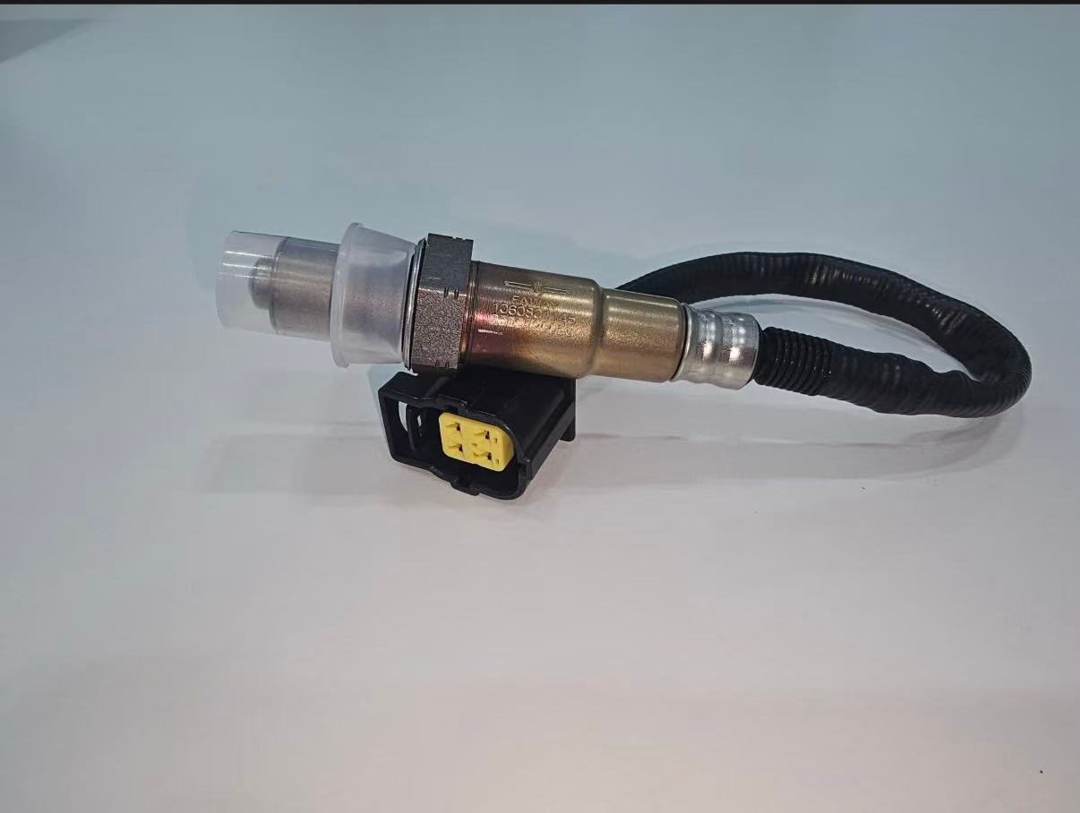
Le due posizioni possono utilizzare diverse tecnologie, riscaldatori, schermature, connettori, lunghezze dei cavi e calibrazioni. Alcuni cataloghi utilizzano legittimamente un componente in più posizioni, ma tale conclusione deve provenire da dati applicativi controllati e aggiornati. Non estendere o accorciare mai il cablaggio di un sensore a montaggio diretto.
| Selezione input | Requisito B1S1 | Requisito B1S2 |
|---|---|---|
| Funzione | Tecnologia di miscelazione-feedback per applicazione esatta | Tecnologia di monitoraggio post-catalizzatore per applicazione esatta |
| Mappatura OE | Mappatura corrente su Bank 1 Sensore 1 | Mappatura corrente su Bank 1 Sensore 2 |
| Connettore | Chiave corretta, perni e circuito | Chiave corretta, perni e circuito |
| Percorso di guida | Raggiunge il connettore a monte con clip approvate | Raggiunge il connettore a valle senza conflitti termici/di movimento |
| Verifica | Risposta della miscela tecnologicamente corretta | Risposta posteriore e contesto del monitor catalizzatore |
Caso composito: abbreviazione lato guida selezionata Bank 2
Scenario di parti composite: Una richiesta dice “a monte lato conducente” e fornisce un codice Bank 1. Lo specialista di ricambi si ferma perché il lato del cilindro 1 del motore non è stato stabilito. Le informazioni di servizio mostrano che il lato conducente è Bank 2 per l'esatta installazione del motore. La richiesta viene corretta con l'identità Bank/Sensore verificata prima del preventivo.
Questo scenario dimostra un controllo di identificazione e non è una rivendicazione su un veicolo specifico o un ordine Sunhyings. Il lato corretto deve sempre provenire da prove di applicazione esatte.
Caso composito: un sensore a valle monitora un percorso unificato
Scenario diagnostico composito: un tecnico si aspetta quattro sensori perché il motore ha due bancate. Lo schema di servizio mostra due sensori a monte specifici per bancata ma un sensore a valle dopo la fusione dei tubi. Contare solo le bancate avrebbe creato un ordine B2S2 inesistente. Il numero effettivo di sensori e le etichette dei monitor sono verificati dallo schema di scarico e dai dati di scansione.
L'esempio è volutamente generico. Dimostra il metodo, non una regola universale di tre sensori. Documentare sempre il motore, la configurazione dello scarico e il mercato delle emissioni.
Registro finale di identificazione Bank/Sensore
- VIN/YMME esatto, codice motore ove pertinente e configurazione mercato/emissioni
- Sorgente verificata del cilindro 1 e conseguente lato fisico della bancata 1
- Diagramma del flusso di scarico e posizione relativa al catalizzatore
- Etichetta dati scansione/DTC abbinata al connettore fisico
- Riferimento OE, tecnologia, connettore, numero di pin, cavo e clip
- Evidenza di test prima/dopo per il circuito nominato
Condurre un'ispezione fisica senza fare supposizioni basate sulla visibilità
Con lo scarico freddo e il veicolo supportato in sicurezza dove è richiesto l'accesso sottoscocca, seguire ogni collettore o ramo di scarico verso il suo catalizzatore. Notare ogni tappo del sensore, ramo del connettore e clip del cablaggio. Usare uno specchio o una fotocamera dove la visibilità diretta è limitata. Non raggiungere lo scarico caldo né fare affidamento sul primo sensore visibile dall'alto.
| Elemento di rilevazione | Registrare | Motivo |
|---|---|---|
| Orientamento del motore | Diagramma longitudinale/trasversale e bancata cilindri | Il lato sinistro/destro del veicolo non definisce la Bancata 1 |
| Posizione del cilindro 1 | Sorgente di servizio e lato fisico | Definisce la Bancata 1 |
| Percorso di scarico | Collettore, punti di giunzione e stadi del catalizzatore | Definisce la posizione del sensore |
| Rami del connettore | ID del connettore, percorso e ritenzione | Previene test incrociati o su ramo errato |
| Etichette esistenti | Marcature OE/parti e orientamento leggibili | Supporta ma non sostituisce i dati di montaggio controllati |
| Evidenza di danni | Calore, sfregamento, acqua, impatti e riparazioni precedenti | Può spiegare i sintomi del circuito |
Utilizzare il confronto banca-banca con attenzione
Su un motore con feedback separato per bancata, il confronto dei correttori di miscela e della risposta a monte può aiutare a distinguere una condizione comune da una specifica di bancata. Una differenza può indicare una perdita localizzata di aspirazione, un iniettore, l'accensione, la compressione, una perdita di scarico, un problema di cablaggio o di sensore. Non identifica da sola il componente guasto. Carichi, temperature e stati di controllo devono essere comparabili.
| Modello osservato | Direzione possibile | Conferma richiesta |
|---|---|---|
| Entrambe le bancate corrette in modo simile | Condizione comune di aria/carburante/misurazione | Ingressi comuni di aspirazione, carburante, flusso d'aria e temperatura |
| La bancata 1 differisce principalmente al minimo | Perdita d'aria o di scarico non misurata specifica del banco | Prova di regolazione rispetto al flusso d'aria e perdite |
| Il banco 1 differisce al minimo e a carico | Differenza di erogazione carburante, sensore/circuito o meccanica | Evidenze di iniettore, accensione, compressione e risposta |
| Il riscaldatore di un banco è inattivo | Guasto specifico del banco al sensore o al circuito | Prova di potenza/carico e revisione del circuito condiviso |
| I segnali del banco posteriore differiscono | Differenza nel percorso del catalizzatore, perdita o sensore | Validità a monte e procedura di monitoraggio esatta |
Confine di installazione dopo l'identificazione della banca/sensore
L'identità corretta non elimina il rischio di installazione. Lasciare raffreddare lo scarico, supportare correttamente il veicolo e seguire la procedura esatta di accesso all'assistenza. Applicare solo la coppia specificata e il trattamento della filettatura. Ripristinare il blocco del connettore, gli schermi termici e ogni clip di instradamento. Non tagliare un cablaggio direct-fit né spostare un sensore su un diverso tappo per far adattare un componente.
Dopo l'installazione, verificare che il canale dei dati di scansione corrisponda ora al sensore fisico e che i test del riscaldatore e della risposta vengano superati. Completare legalmente il monitor applicabile. Cancellare il DTC o vedere la spia di avvertimento spegnersi prima che il monitor venga eseguito non è una verifica completa.
Analisi di ritorno banca errata e posizione errata
| Reclamo | Prove da raccogliere | Categorie possibili |
|---|---|---|
| Il connettore non si innesta | Superfici del connettore, perni, etichette, veicolo e posizione | Parte sbagliata, posizione errata, errore di catalogo o imballaggio |
| Il cavo non arriva | Percorso completo, punti di fissaggio, lunghezza vecchia/nuova e identità del componente | Banco/posizione sbagliati, parte errata o instradamento non corretto |
| Il codice persiste dopo la sostituzione | Codici prima/dopo, test del circuito e di risposta | Sensore sbagliato sostituito, guasto del veicolo non risolto o problema del componente |
| Dati della sponda opposta modificati | Mappa connettori e instradamento cablaggio | Connettori incrociati o errore di scansione/mappatura fisica |
| Danno fisico da calore | Gioco di installazione, schermature, clip e movimento | Instradamento, lunghezza di applicazione o protezione mancante |
Dati RFQ per un sensore di ossigeno specifico della banca
Per l'approvvigionamento, inviare il candidato di riferimento OE, l'identità completa di veicolo/motore/emissioni, la designazione di Bancata e Sensore, la fonte del cilindro 1, foto di connettore e vecchia parte, misure di cavo/clip, quantità, requisiti di mercato e approvazione. Sunhyings può esaminare l'ambito presentato per la fattibilità dell'approvvigionamento. Idoneità, disponibilità, prezzo, MOQ, tempi di consegna e certificazione rimangono non confermati fino a quando le prove a livello di parte non corrispondono.
Risolvere informazioni di posizione contrastanti con una gerarchia di fonti
I conflitti di posizione sono comuni quando un lettore di codici generico, un annuncio di marketplace, una foto di forum e una scorciatoia di officina usano denominazioni diverse. Iniziare con le informazioni di assistenza esatte del veicolo e i dati applicativi controllati per VIN/configurazione. Utilizzare la parte rimossa e il layout fisico come prove di supporto. Un forum o un'immagine non etichettata può suggerire cosa controllare, ma non dovrebbe controllare un ordine specifico per bancata.
| Fonte | Utile per | Controllo richiesto | Azione di conflitto |
|---|---|---|---|
| Informazioni sul servizio OEM | Numerazione cilindri, posizione componenti, cablaggio e metodo di prova | Modello/motore/mercato esatto e documento corrente | Confermare applicabilità e sostituzione |
| Catalogo parti controllate | Mappatura candidati OE e aftermarket | Campo revisione, fonte e banca/sensore | Mantieni la riga se l'evidenza di servizio/fisica differisce |
| Registri VIN/costruzione/emissioni | Configurazione del veicolo e punti di interruzione | Identità leggibile completa | Risolvi dati di costruzione mancanti o incoerenti |
| Marcatura del componente rimosso | Identità di conferma dal componente installato | Numero leggibile e posizione originale nota | Verificare se la riparazione precedente ha installato un componente errato |
| Connettore fisico/disposizione | Confronto di instradamento e interfaccia | Foto che mostrano il contesto, non solo il connettore ritagliato | Non forzare l'adattamento; confrontare con i registri |
| Contenuto di ricerca/forum | Generazione di domande per la verifica | Nessuna autorità per il montaggio definitivo | Sostituire con fonte controllata |
Caso composito: le etichette di scansione erano corrette ma i connettori erano incrociati
Scenario del reparto compositi: dopo una riparazione del motore, i dati a monte di Bank 1 e Bank 2 appaiono invertiti durante un confronto controllato della miscela. La numerazione dei cilindri e le etichette di scansione sono corrette. Un'indagine sul cablaggio rileva due connettori vicini incrociati durante il rimontaggio. Ripristinando il percorso dei connettori documentato si allinea la risposta fisica con i canali bancari previsti.
Il caso illustra perché un semplice lettore di codici non può dimostrare quale sensore fisico è collegato. Mostra anche come la sostituzione di entrambi i sensori avrebbe preservato l'errore di cablaggio. Questo è un modello composito, non un caso cliente Sunhyings né una dichiarazione su qualsiasi marca di veicolo.
Prova post-riparazione per Banca 1 Sensore 1 o Sensore 2
Verificare il numero di parte, il blocco del connettore, le posizioni delle clip, la distanza dal calore e la tenuta dello scarico. Per il Sensore 1, documentare la risposta corretta dal punto di vista tecnologico e il controllo del carburante della bancata plausibile in condizioni valide. Per il Sensore 2, documentare il circuito/risposta e il contesto applicabile del monitor del catalizzatore. Confrontare il risultato con il guasto originale; non dichiarare il successo solo perché i codici sono stati cancellati.
Se la bancata opposta o un altro sensore ora imposta un codice, rivedere le alimentazioni condivise, la mappatura dei connettori e l'intero sistema prima di ipotizzare un secondo guasto indipendente. Conservare i codici permanenti e le informazioni di prontezza secondo la procedura del veicolo e normativa.
Un registro finale difendibile indica chi ha verificato la sorgente del cilindro 1, quale revisione del documento è stata utilizzata, quale connettore fisico è stato riparato e quale canale dati è stato controllato successivamente. Questo livello di tracciabilità è particolarmente importante quando un'officina, un distributore e un fornitore gestiscono diverse parti della richiesta.
Non pubblicare una regola lato Bank 1 per un intero marchio. Anche all'interno di una stessa marca, le famiglie di motori e le orientazioni di installazione possono differire. Un articolo a livello di marca può insegnare il metodo di identificazione, ma solo l'evidenza del veicolo a livello di parte può supportare un'affermazione di montaggio.
Quando i dati affidabili sulla numerazione dei cilindri o sulla disposizione dello scarico non sono disponibili, contrassegnare la decisione sulla posizione DATI NON DISPONIBILI e fermare l'ordine. Indovinare un lato crea rischi evitabili di installazione, reso e sistema di emissioni. Richiedere il VIN, i dettagli del motore o uno schema autorevole piuttosto che trasformare l'incertezza in una presunta compatibilità.
Per applicazioni B2 o Sensore 3, utilizzare lo stesso metodo piuttosto che estendere una regola B1S1/B1S2. Il banco rimane legato alla numerazione dei cilindri, mentre il numero del sensore deve essere tracciato attraverso la disposizione esatta del catalizzatore. Il confronto principale di questa pagina rimane B1S1 rispetto a B1S2, ma la disciplina delle prove si applica a ogni posizione monitorata aggiuntiva.
Prepara una richiesta di adattamento o approvvigionamento
Invia il numero OE, anno/marca/modello, motore o dettagli VIN, mercato e pacchetto emissioni, posizione esatta di banco/sensore, connettore e foto del vecchio componente, quantità e eventuali requisiti di imballaggio o approvazione. Sunhyings esaminerà i dati forniti per verificarne la capacità e la fattibilità dell'approvvigionamento; l'adattamento non è confermato fino a quando le prove di applicazione non vengono abbinate.
Domande frequenti
Il sensore 1 del banco 1 è a monte?
Generalmente è il sensore a monte o pre-catalizzatore sul banco contenente il cilindro 1.
Il sensore 2 del banco 1 è a valle?
Generalmente è il sensore a valle o post-catalizzatore della Banca 1.
La Bank 1 si trova sul lato guidatore?
Non universalmente. Il banco 1 è definito dal cilindro 1, e il suo lato fisico dipende dal motore.
Il Sensore 1 e il Sensore 2 possono utilizzare la stessa parte?
Solo quando i dati applicativi verificati elencano la parte esatta per entrambe le posizioni. Filettature o tappi simili non sono sufficienti.
Un codice Bank 1 Sensor 2 significa che bisogna sostituire quel sensore?
No. Identifica il circuito o il monitor da diagnosticare; anche le condizioni del cablaggio, dello scarico e del catalizzatore possono essere coinvolte.