








الدليل الفني لحساس الأكسجين
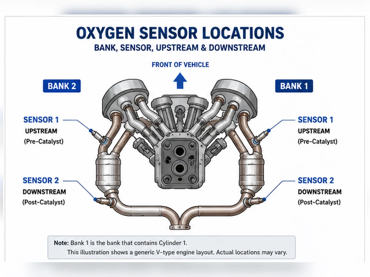
عادةً ما يكون المستشعر 1 في البنك 1 قبل المحول الحفاز والمستشعر 2 في البنك 1 بعده، ولكن يجب تأكيد الموقع من خلال موقع الأسطوانات ومخطط عادم المركبة.
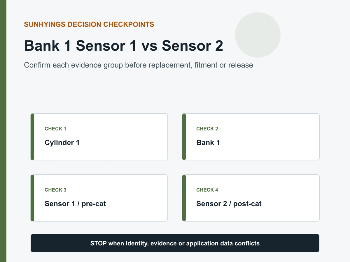
إجابة سريعة
المستشعر 1 في البنك 1 هو عمومًا مستشعر الأكسجين أو نسبة الهواء إلى الوقود قبل المحول الحفاز على البنك الذي يحتوي على الأسطوانة 1. المستشعر 2 في البنك 1 هو عمومًا المستشعر بعد ذلك المحفز. غالبًا ما يدعم المستشعر 1 تغذية التحكم في الوقود، بينما يدعم المستشعر 2 عادةً مراقبة المحفز. تأكد من ترقيم أسطوانات المحرك وتخطيط العادم قبل التشخيص أو الطلب.
فك تشفير الاسم بالترتيب الصحيح
هذه الطريقة أكثر موثوقية من “يسار” أو “يمين” أو “أمام” أو “خلف”، والتي قد يتغير معناها مع التركيب الطولي والعرضي للمحرك.
مقارنة المستشعر 1 والمستشعر 2 في البنك 1
| تفاصيل | البنك 1 الحساس 1 | مستشعر البنك 1 الحساس 2 |
|---|---|---|
| موقع شائع | قبل المحول / قبل الحفاز | بعد المحول / بعد الحفاز |
| دور شائع | تغذية راجعة للخليط | مراقبة المحفز |
| التقنية | قد يكون ضيق النطاق أو عريض النطاق/نسبة الهواء إلى الوقود | غالبًا ضيق النطاق، لكن بيانات التطبيق تتحكم |
| خطأ شراء شائع | بنك أو تقنية أو موصل خاطئ | طول كابل خاطئ، أو مسار غير صحيح، أو موضع مستشعر بعد المحفز |
كيف يظهر الموضع في رموز الأعطال
قد يذكر وصف الكود المستشعر 1 في البنك 1 أو المستشعر 2 في البنك 1، لكن ذلك لا يزال يحدد دائرة أو حالة مراقبة بدلاً من جزء معطل مؤكد. اختبر الأسلاك، مصدر تيار السخان، حالة الموصل وسلوك الإشارة. بالنسبة لأكواد الخليط أو المحفز، افحص أيضًا أسباب المحرك والعادم.
لماذا قد لا يكون المستشعران قابلين للتبادل
قد تختلف في تقنية المستشعر، المعايرة، الدرع الواقي، ترميز الموصل، طول الكابل ومشابك التوجيه حتى عندما تبدو الخيوط متطابقة. طابق رقم المعدات الأصلي والتطبيق المؤكد للموضع الدقيق. لا تقم أبدًا بتمديد أو إجبار مجموعة الأسلاك المباشرة لجعل المستشعر الخاطئ يصل.
سجل التحقق من الطلب المسبق
- رقم الشاصي أو السنة/الماركة/الموديل/المحرك كاملة
- حزمة السوق والانبعاثات
- موقع الأسطوانة 1 والبنك 1
- المستشعر 1 أو المستشعر 2 بالنسبة للمحفز
- المرجع الأصلي والمرجع المتقاطع الحالي
- وجه الموصل، التشفير، الدبابيس، طول الرصاص والمشابك
ابحث عن البنك 1 قبل البحث عن رقم المستشعر
البنك 1 هو مجموعة الأسطوانات التي تحتوي على الأسطوانة 1. يعتمد جانب الأسطوانة 1 على تصميم المحرك وتركيبه، لذا فإن البنك 1 ليس عالميًا جانب السائق أو الراكب أو الأمام أو الخلف. استخدم مخطط ترقيم الأسطوانات الخاص بالشركة المصنعة للمحرك المحدد. في المحرك الخطي، عادة ما يكون هناك بنك واحد فقط، لكن المصطلحات الخدمية لا تزال سارية.
| اختصار | لماذا يفشل | دليل موثوق |
|---|---|---|
| البنك 1 دائمًا جانب السائق | يختلف ترقيم الأسطوانات | مخطط خدمة المحرك |
| البنك الأمامي يعني البنك 1 | الاتجاه العرضي يختلف | موقع الأسطوانة 1 |
| صورة رمز واحد تحدد الموصل | يمكن أن يعبر توجيه الحزام المحرك | مخططات الأسلاك والعادم |
| المحرك الخطي يحتوي على البنك 2 | تسميات المسح العامة قد لا تكون مدعومة | دعم البيانات الخاصة بالمركبة |
تتبع تدفق العادم لتحديد المستشعر 1 والمستشعر 2
البنك 1 الحساس 1
المستشعر 1 هو عادة مستشعر الأكسجين أو نسبة الهواء إلى الوقود قبل المحفز المعني على البنك 1. وهو يدعم عادةً تغذية راجعة للخليط بعد استيفاء شروط التمكين. قد تكون تقنيته ضيقة النطاق أو عريضة النطاق/نسبة الهواء إلى الوقود أو تصميم آخر محدد.
مستشعر البنك 1 الحساس 2
يوجد المستشعر 2 عادةً بعد المحفز المراقب في البنك 1 ويدعم مراقبة نظام المحفز. تستخدم بعض التصميمات مستشعرات إضافية أو تسميات خاصة بالشركة المصنعة. تأكد من ترتيب العادم الفعلي بدلاً من عد الموصلات من المحرك إلى الخارج بدون رسم تخطيطي.
لماذا “أمامي” و“خلفي” غامضان
في المحرك العرضي، قد يصف “أمامي” جانب السيارة أو بنك المحرك أو الموضع العلوي. قائمة الأجزاء التي تقول أمامي/خلفي بدون سياق البنك/المستشعر والمحرك غير مكتملة.
مقارنة أدوارهما المشتركة والأدلة
| عنصر قرار | البنك 1 الحساس 1 | مستشعر البنك 1 الحساس 2 |
|---|---|---|
| موقع شائع | قبل محفز البنك 1 | بعد محفز البنك 1 |
| دور شائع | تغذية راجعة للخليط | مراقبة المحفز |
| تفسير البيانات | استجابة غنية/فقيرة أو واسعة النطاق خاصة بالتكنولوجيا | مقارنة مع سلوك المحفز والمنبع |
| مخاطر الطلب النموذجية | تقنية أو بنك خاطئ | طول سلك أو مسار أو موضع ما بعد المحفز خاطئ |
كيف يظهر الموضع في أوصاف DTC
رمز تسمية مثل Bank 1 Sensor 1 أو Bank 1 Sensor 2 يحدد الدائرة أو مسار المراقبة. لا يثبت فشل عنصر الاستشعار. رمز السخان يحتاج إلى فحص التغذية والأرضي/التحكم والموصل والعنصر؛ رمز المنخفض/المرتفع أو الاستجابة يحتاج إلى فحص الدائرة وحالة التشغيل والتسرب وأدلة الخليط. P0420 يتعلق بكفاءة نظام المحفز وليس أمرًا تلقائيًا لاستبدال B1S2.
| صياغة الرمز | سؤال الموضع | سؤال التشخيص |
|---|---|---|
| سخان B1S1 | موصل بنك 1 قبل المحفز صحيح؟ | هل يتم توصيل الطاقة/التحكم وفق الشروط المحددة؟ |
| B1S1 منخفض/مرتفع | الدائرة العلوية صحيحة؟ | حد كهربائي أم خليط حقيقي؟ |
| B1S2 لا نشاط | موصل بعد المحفز صحيح؟ | PID مدعوم وموصول ومزوّد بالطاقة والتسخين؟ |
| P0420 البنك 1 | أي مسار محفز تتم مراقبته؟ | المحرك، التسرب، الحساسات أو حالة المحفز؟ |
تتبع الموصلات دون إنشاء عطل جديد
اترك العادم ليبرد واستخدم معدات الدعم المعتمدة. اتبع كابل كل حساس إلى موصله دون سحب الأسلاك. لاحظ المشابك، أكمام الحماية ومسارات العبور. لا تفصل عدة موصلات متطابقة المظهر دون وضع علامات عليها؛ إعادة توصيل الحساسات بفرع الحزام الخطأ يمكن أن يولد رموزًا مضللة ومسارات غير آمنة.
مطابقة البيانات الحية مع المستشعر الفعلي
تأكد من PID أداة المسح، الوحدات والتقنية المدعومة. راقب الحساس 1 في البنك 1 تحت ظروف الحلقة المغلقة الصالحة والحساس 2 في البنك 1 في سياق مراقبة المحفز المحدد في معلومات الخدمة. لا تقارن معامل تيار عريض النطاق بقاعدة جهد ضيق النطاق. إذا كان فصل الموصل جزءًا من اختبار رسمي، اتبع ذلك الإجراء وتجنب استخدام الفصل كطريقة تعريف مرتجلة.
لماذا قد لا يتم تبادل المستشعر 1 والمستشعر 2
قد تشترك في حجم السن اللولبي لكنها تختلف في التقنية، السخان، المعايرة، الدرع، ترميز الموصل، تخصيص الدبوس، طول الكابل والمشابك. طابق المرجع الأصلي، السيارة/المحرك/السوق، الموضع الدقيق وسجل التطبيق الحالي. لا تقطع، تمد أو تجبر حزامًا مباشرًا ليجعل حساسًا مخصصًا لموضع آخر يصل.
| فحص التوافق | الدليل المطلوب | ارفض عندما |
|---|---|---|
| مرجع الشركة المصنعة للمعدات الأصلية | التعيين الحالي لـ B1S1 أو B1S2 | القائمة توضح الموديل فقط |
| التقنية | تصميم استشعار/تحكم محدد | عدد الأسلاك هو المطابقة الوحيدة |
| موصل | تحديد المفاتيح وتعيين الأطراف | القابس يتطلب قوة |
| توجيه السلك | الطول، الكم والمشابك | ملامسات الكابل للحرارة/الحركة |
سيناريو مركب: البنك الصحيح على الجانب غير المتوقع
سيناريو تشخيصي مركب: يبدأ الإصلاح عند مستشعر جهة الراكب لأن منتدى عام يسمي تلك الجهة البنك 1. يُظهر مخطط المحرك الأسطوانة 1 على البنك المقابل. نقل الاختبار إلى الدائرة المسماة بالرمز يمنع استبدال مستشعر يعمل. هذا نمط تعليمي مركب، وليس ادعاءً بخصوص مركبة أو تركيب من صنع Sunhyings.
إنشاء سجل للتحقق من الموضع
احفظ مخطط المحرك/الأسطوانة، وصف الرمز، رسم مسار العادم، صورة الموصل، الرقم الأصلي ومسار الكابل المُقاس. بعد الإصلاح، تأكد من استجابة PID الصحيحة، وأن الحزام بعيد عن الحرارة وأن المراقبة المطبقة تكتمل. يجب تحديد اليقين في الموضع قبل التشخيص ومرة أخرى قبل الطلب.
سير عمل قابل للتكرار لتحديد البنك 1
الخطوة 1: تحديد المحرك الدقيق
سجل معلومات المحرك المستمدة من رقم الشاصي، رمز المحرك إن وجد، سوق البيع وملصق الانبعاثات. لا تستخدم مخططًا لإزاحة أو سنة موديل أخرى لمجرد أن غطاء المحرك يبدو مشابهًا.
الخطوة 2: تحديد موقع الأسطوانة 1
استخدم معلومات الخدمة من الشركة المصنعة للعثور على الأسطوانة 1 وبنك الأسطوانات. ضع علامة على البنك 1 على نسخة من المخطط. إذا كان المحرك خطيًا، تأكد من أن تسمية البنك 2 ليست عنصرًا عامًا غير مدعوم من أداة الفحص.
الخطوة 3: تعيين المحفزات وترتيب المستشعرات
تتبع تدفق العادم من البنك 1. حدد موضع الاستشعار الأول قبل المحفز المعني والموضع المراقب بعده. ضع في الاعتبار المحفزات القريبة والفروع التي قد تكون مخفية بواسطة الدروع.
الخطوة 4: التوفيق بين الأسلاك والتوجيه الفيزيائي
اتبع الرسم التخطيطي من المستشعر المسمى إلى موصله ودائرة وحدة التحكم. يمكن أن تعبر الأحزمة المحرك أو تنضم إلى حامل مشترك، لذا فإن القرب من البنك لا يثبت الهوية الكهربائية.
| مخرجات سير العمل | تسجيل | السبب |
|---|---|---|
| هوية المحرك | رمز المحرك/سياق رقم الشاصي والسوق | يختار الرسوم التخطيطية الصحيحة |
| هوية البنك | جانب الأسطوانة 1 | يلغي الاختصارات الجانبية |
| هوية المستشعر | ترتيب المحفز قبل/بعد | يفصل بين المستشعر 1 والمستشعر 2 |
| هوية الدائرة | مسار الموصل والدبوس | يضمن وصول الاختبار إلى الدائرة المسماة |
إذا كانت معلومات الخدمة والملاحظة الفعلية لا تزال متضاربة، فتوقف وارفع مستوى التعريف بدلاً من اختيار جانب بالاتفاق. قد تكون الإصلاحات السابقة قد أعادت توجيه الموصلات أو ركبت الجزء الخطأ. سجل التعارض، وتسميات الموصلات، وألوان الأسلاك فقط كحقائق ملاحظة، واستنفد السياق حتى يتمكن المراجع التالي من حل الدائرة دون تكرار الافتراضات. لا تقم بإعادة توصيل فروع الحزام المتقاطعة فقط لمعرفة الرمز الذي يظهر؛ استخدم الرسم التخطيطي وإجراء الاستمرارية، ثم احتفظ بالتخطيط الموثق مع سجل الإصلاح.
طريقة قابلة للتكرار لتحديد البنك 1
البنك 1 هو الجانب أو مسار العادم الذي يحتوي على الأسطوانة 1. المستشعر 1 هو عادة المستشعر قبل المحفز لذلك البنك؛ المستشعر 2 هو عادة المستشعر بعد المحفز المراقب. الكلمات “عادة” و“لذلك البنك” مهمة. استخدم معلومات المحرك والعادم الدقيقة عندما تتضمن التصاميم أنابيب مدمجة أو محفزات متعددة أو أكثر من مستشعرين.
- تأكد من المحرك الدقيق، وليس فقط الإزاحة أو شارة الموديل.
- ابحث عن ترقيم الأسطوانات من معلومات الخدمة الموثقة.
- حدد جانب الأسطوانة 1 أو مجرى العادم.
- تتبع تدفق العادم عبر المحفز ذي الصلة.
- اربط المستشعر 1 والمستشعر 2 بالموصلات الفعلية وتسميات بيانات المسح.
- قم بتصوير المسار أو تسجيله قبل فصل أي شيء.
| اختصار | لماذا يفشل | بديل موثوق |
|---|---|---|
| البنك 1 هو دائمًا جانب السائق | يختلف اتجاه المحرك وترقيم الأسطوانات | حدد موقع الأسطوانة 1 من معلومات الخدمة |
| المستشعر 1 هو الأسهل دائمًا للرؤية من الأعلى | يمكن أن يضع التغليف مستشعر ما قبل المحفز خلف المحرك | تتبع تدفق العادم قبل المحفز |
| المستشعر 2 يعني الموصل الثاني الموجود | ترتيب الأسلاك لا يحدد موضع العادم | حدد موقع الحساس بعد المحفز المراقب |
| P013x تعني دائمًا البنك 1 | يجب قراءة لاحقة الكود والعائلة بالكامل | استخدم الوصف الكامل والتطابق الدقيق لرمز DTC |
| الأمامي/الخلفي يساوي الحساس 1/2 | اتجاه المركبة ليس علاقة بالمحفز | استخدم هوية قبل المحفز/بعد المحفز |
كيف يغير تخطيط المحرك والعادم الخريطة
| التكوين | معنى البنك | مشكلة ترقيم الحساسات | البيانات المطلوبة |
|---|---|---|---|
| محرك خطي | عادةً مجموعة أسطوانات واحدة | قد لا يزال يحتوي على حساسات/محفزات متعددة | مخطط العادم الدقيق وعدد الحساسات |
| محرك V طولي | المجموعات اليسرى/اليمنى حسب ترقيم الأسطوانات | لا يمكن تعميم الجانب الفعلي عبر الماركات | رمز المحرك وتخطيط الأسطوانات |
| محرك V عرضي | بنك واحد نحو الحاجز الناري، وآخر نحو الرادياتير | البنك الأمامي ليس بالضرورة البنك 1 | موقع الأسطوانة 1 واتجاه التركيب |
| محرك متقابل | جوانب أسطوانات منفصلة | الافتراضات الجانبية الشائعة تظل غير آمنة | ترقيم أسطوانات المصنع |
| عادم مدمج | قد تندمج المسارات العلوية الخاصة بكل بنك | يمكن أن يصبح المراقبة السفلية مشتركة | تخطيط كامل للحافز والأنابيب |
| مراحل حفاز متعددة | هوية البنك تظل مرتبطة بالأسطوانات | تسمية الحساس 2/3 تحتاج إلى رسم بياني دقيق | موقع مكون الخدمة وتعريف رمز التشخيص (DTC) |
استخدم الرمز لتحديد مسار الاختبار، ثم تحقق من المستشعر الفعلي
| مجموعة رموز مثال | منطقة مسماة | تأكيد فيزيائي | حدود الاختبار |
|---|---|---|---|
| P0130-P0135 | عادةً عائلات إشارة/استجابة/سخان الحساس 1 في البنك 1 | حساس ما قبل المحفز على الأسطوانة 1 البنك | وصف الكود الكامل والتحكم المنطقي للخدمة |
| P0136-P0141 | عائلات إشارة/استجابة/سخان حساس البنك 1 الشائعة | حساس ما بعد المحفز لمسار البنك 1 | ليس استبدالًا تلقائيًا للمحفز أو الحساس |
| P0150-P0155 | عائلات حساس البنك 2 الشائعة | حساس ما قبل المحفز على البنك المقابل | لا تزال أسباب الخليط الفعلي والدائرة سارية |
| P0156-P0161 | عائلات شائعة للحساس 2 في البنك 2 | حساس ما بعد المحفز لمسار البنك 2 | الإشارة الخلفية تحتاج إلى سياق مراقبة |
| P0420 | كفاءة المحفز أقل من الحد الأدنى، البنك 1 | مسار المحرك/العادم/الحساس/المحفز بالكامل للبنك 1 | لا يطلب B1S2 |
| P0430 | كفاءة المحفز أقل من الحد الأدنى، المجموعة 2 | مسار المجموعة 2 بالكامل | لا يطلب B2S2 |
قم بتعيين بيانات المسح إلى الموصل قبل الحكم على شكل الموجة
استخدم مخطط الخدمة وطريقة تأكيد غير مدمرة. قارن استجابة المجموعة المحددة بتغيير تشغيلي محكوم حيث تسمح الإجراءات. إذا كان فصل أو معالجة دائرة جزءًا من اختبار الشركة المصنعة للمعدات الأصلية، فاتبع احتياطاتها. لا تُحدث قصرًا، أو تثقب العزل دون إصلاح، أو تطبق توقع جهد ضيق النطاق على دائرة عريضة النطاق.
| دليل | يؤكد | لا يؤكد بمفرده |
|---|---|---|
| مخطط ترقيم الأسطوانات | أي جانب يحتوي على الأسطوانة 1 | مسار موصل الحساس |
| مخطط مكونات العادم | موضع الحساس بالنسبة للحافز | رقم القطعة الصحيح القابل للبيع |
| رسم تخطيطي للأسلاك | دائرة، أطراف، طاقة وتحكم مشتركة | سدادة فيزيائية بدون عرض الموقع |
| ملصق بيانات المسح | قناة البنك/الحساس المبلغ عنها من الوحدة | أن مجموعة الأسلاك متصلة بالحساس المخصص |
| كتالوج المعدات الأصلية/التطبيقات | تخطيط القطعة المرشحة | التشخيص أو صحة الموصل بعد أعمال الإصلاح |
B1S1 و B1S2 ليسا تسميتين قابلتين للتبادل
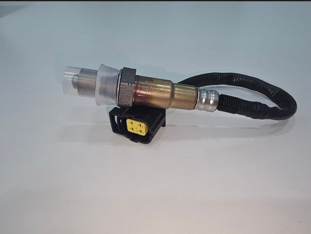
يمكن للموضعين استخدام تقنيات مختلفة، وسخانات، وشاشات، وموصلات، وأطوال أسلاك، ومعايرة. بعض الكتالوجات تستخدم بشكل مشروع قطعة واحدة في مواضع متعددة، ولكن هذا الاستنتاج يجب أن يأتي من بيانات تطبيقية محكومة حالية. لا تقم أبدًا بجعل حساس التوصيل المباشر يصل عن طريق قطع أو تمديد مجموعة الأسلاك الخاصة به.
| مدخل الاختيار | متطلبات B1S1 | متطلبات B1S2 |
|---|---|---|
| الوظيفة | تقنية التغذية الراجعة للخليط للتطبيق الدقيق | تقنية مراقبة ما بعد المحفز للتطبيق الدقيق |
| رسم الخرائط الأصلي (OE) | رسم الخرائط الحالي للمستشعر 1 في البنك 1 | رسم الخرائط الحالي للمستشعر 2 في البنك 1 |
| موصل | المفتاح الصحيح والدبابيس والدائرة | المفتاح الصحيح والدبابيس والدائرة |
| مسار السلك | يصل إلى الموصل العلوي باستخدام المشابك المعتمدة | يصل إلى الموصل السفلي دون تعارض حراري/حركي |
| التحقق | استجابة صحيحة تقنيًا ومختلطة | الاستجابة الخلفية وسياق مراقب المحفز |
حالة مركبة: اختصار جانب السائق يحدد البنك 2
سيناريو الأجزاء المركبة: طلب يقول “الجهة العلوية للسائق” ويوفر رمز البنك 1. يتوقف أخصائي قطع الغيار لأن جانب الأسطوانة 1 للمحرك لم يتم تحديده. تُظهر معلومات الخدمة أن جانب السائق هو البنك 2 لتثبيت المحرك المحدد. يتم تصحيح الطلب إلى هوية البنك/الحساس المؤكدة قبل عرض السعر.
يُظهر هذا السيناريو مراقبة تحديد الهوية وليس ادعاءً حول مركبة مسماة أو طلب Sunhyings. يجب دائمًا أن يأتي الجانب الصحيح من أدلة التطبيق الدقيقة.
حالة مركبة: مستشعر واحد في اتجاه المصب يراقب مسارًا مدمجًا
سيناريو تشخيصي مركب: يتوقع فني وجود أربعة حساسات لأن المحرك يحتوي على بنكين. يُظهر مخطط الخدمة حساسين علويين خاصين بالبنك ولكن حساسًا سفليًا واحدًا بعد دمج الأنابيب. عدّ البنوك فقط كان سيؤدي إلى طلب B2S2 غير موجود. يتم التحقق من العدد الفعلي للحساسات وتسميات المراقب من مخطط العادم وبيانات الفحص.
المثال عام عن قصد. إنه يثبت الطريقة، وليس قاعدة عالمية لثلاثة حساسات. وثّق دائمًا المحرك وتكوين العادم وسوق الانبعاثات.
سجل تحديد البنك/المستشعر النهائي
- VIN/YMME الدقيق، ورمز المحرك حيثما كان ذا صلة، وتكوين السوق/الانبعاثات
- مصدر الأسطوانة 1 المؤكد والجانب الفعلي الناتج للبنك 1
- مخطط تدفق العادم وموضعه بالنسبة للمحفز
- بيانات الفحص/رمز DTC المطابق للموصل الفعلي
- المرجع الأصلي، التقنية، الموصل، عدد الأطراف، السلك والمشابك
- دليل الفحص قبل/بعد للدائرة المحددة
إجراء مسح فيزيائي دون تخمين بناءً على الرؤية
مع برودة العادم ودعم المركبة بأمان حيث يتطلب الوصول إلى أسفل الهيكل، اتبع كل مشعب أو فرع عادم نحو المحفز. لاحظ كل فتحة حساس، وفرع الموصل، ومشبك الأسلاك. استخدم مرآة أو كاميرا عندما تكون الرؤية المباشرة محدودة. لا تصل حول عادم ساخن أو تعتمد على أول حساس مرئي من الأعلى.
| عنصر المسح | تسجيل | السبب |
|---|---|---|
| اتجاه المحرك | مخطط طولي/عرضي وبنية الأسطوانات | الجهة اليسرى/اليمنى للمركبة لا تحدد البنك 1 |
| موقع الأسطوانة 1 | مصدر الخدمة والجانب الفعلي | يحدد البنك 1 |
| مسار العادم | المشعب، نقاط الدمج ومراحل المحفز | يحدد موضع الحساس |
| فروع الموصل | معرفات الموصل، المسار والتثبيت | يمنع الاختبار المتقاطع أو الاختبار على الفرع الخاطئ |
| الملصقات الموجودة | علامات OE/الأجزاء والاتجاه قابلة للقراءة | يدعم بيانات التركيب المتحكم بها ولكنه لا يحل محلها |
| دليل التلف | الحرارة، الاحتكاك، الماء، الصدمات والإصلاح السابق | يمكن أن يفسر أعراض الدائرة |
استخدام المقارنة بين البنوك بحذر
في محرك مزود بتغذية راجعة منفصلة لكل بنك، يمكن أن تساعد مقارنة تصحيحات الوقود واستجابة المشعب العلوي في التمييز بين حالة مشتركة وحالة خاصة ببنك معين. قد يشير الاختلاف إلى تسرب سحب موضعي، أو حاقن، أو إشعال، أو ضغط، أو تسرب عادم، أو مشكلة في الأسلاك أو المستشعر. لا يحدد بحد ذاته الجزء المعطل. يجب أن تكون الأحمال ودرجات الحرارة وحالات التحكم قابلة للمقارنة.
| النمط الملاحظ | اتجاه محتمل | التأكيد المطلوب |
|---|---|---|
| تم تصحيح البنكين بشكل مماثل | حالة مشتركة للهواء/الوقود/القياس | مدخلات مشتركة للسحب والوقود وتدفق الهواء ودرجة الحرارة |
| البنك 1 يختلف بشكل رئيسي عند التباطؤ | تسرب هواء غير مقاس أو تسرب عادم خاص بالبنك | اختبار التصحيح مقابل تدفق الهواء واختبار التسرب |
| اختلاف البنك 1 عند التباطؤ والحمل | توصيل الوقود، حساس/دائرة أو فرق ميكانيكي | دليل الحاقن، الإشعال، الضغط والاستجابة |
| سخان أحد البنكين غير نشط | خلل في الحساس أو الدائرة خاص بالبنك | اختبار طاقة/تحكم محمّل ومراجعة الدائرة المشتركة |
| إشارات البنك الخلفي مختلفة | مسار المحفز، تسرب أو فرق في الحساس | صلاحية المنبع وإجراءات المراقبة الدقيقة |
حدود التركيب بعد تحديد البنك/الحساس
الهوية الصحيحة لا تزيل خطر التركيب. اترك العادم ليبرد، وادعم المركبة بشكل صحيح واتبع إجراءات الوصول للخدمة بدقة. طبق عزم الربط المحدد ومعالجة الخيوط فقط. أعد قفل الموصل والدروع الحرارية وكل مشابك التوجيه. لا تقطع مجموعة الأسلاك المباشرة أو تنقل الحساس إلى فتحة مختلفة لجعل الجزء مناسبًا.
بعد التركيب، أثبت أن قناة بيانات الفحص تتوافق الآن مع المستشعر الفعلي وأن اختبارات السخان والاستجابة تنجح. أكمل جهاز المراقبة المطبق قانونيًا. مسح رمز DTC أو رؤية مصباح التحذير ينطفئ قبل تشغيل جهاز المراقبة ليس تحققًا كاملاً.
تحليل إرجاع البنك الخاطئ والموضع الخاطئ
| الشكوى | الأدلة المطلوب جمعها | الفئات المحتملة |
|---|---|---|
| الموصل لا يتعشّق | أسطح الموصل، الدبابيس، الملصقات، المركبة والموضع | جزء خاطئ، موضع خاطئ، خطأ في الكتالوج أو التعبئة |
| السلك لا يصل | المسار الكامل، نقاط التثبيت، الطول القديم/الجديد وهوية القطعة | بنك/موضع خاطئ، قطعة خاطئة أو مسار غير صحيح |
| يبقى الرمز بعد الاستبدال | الرموز قبل/بعد، اختبارات الدائرة والاستجابة | تم تغيير حساس خاطئ، عطل مركبة غير محلول أو مشكلة قطعة |
| تغيرت بيانات البنك المقابل | خريطة الموصلات ومسار الأسلاك | موصلات متقاطعة أو خطأ في الفحص/التخطيط الفيزيائي |
| ضرر حراري فيزيائي | الخلوص المركب، الواقيات، المشابك والحركة | المسار، طول التطبيق أو الحماية المفقودة |
بيانات طلب عرض سعر لحساس أكسجين خاص ببنك معين
للتوريد، أرسل المرجع الأصلي المرشح، هوية المركبة/المحرك/الانبعاثات الكاملة، تعيين البنك والحساس، مصدر الأسطوانة الأولى، صور الموصل والجزء القديم، قياسات السلك/المشبك، الكمية، متطلبات السوق والموافقة. يمكن لشركة Sunhyings مراجعة النطاق المقدم لجدوى التوريد. يبقى التركيب، المخزون، السعر، الحد الأدنى للطلب، المهلة الزمنية والشهادة غير مؤكدة حتى يتم مطابقة الأدلة على مستوى الجزء.
حل معلومات الموضع المتضاربة باستخدام تسلسل هرمي للمصادر
تضارب المواضع شائع عندما يستخدم قارئ أكواد عام، قائمة سوق، صورة منتدى واختصار ورشة أسماء مختلفة. ابدأ بمعلومات خدمة المركبة الدقيقة وبيانات التطبيق المتحكم بها لتكوين VIN/الإعداد. استخدم الجزء المُزال والترتيب الفيزيائي كدليل داعم. يمكن أن يقترح منتدى أو صورة غير معنونة ما يجب فحصه، لكن لا ينبغي أن يتحكم في طلب خاص ببنك.
| المصدر | مفيد لـ | التحكم مطلوب | إجراء التعارض |
|---|---|---|---|
| معلومات خدمة OEM | ترقيم الأسطوانات، موقع المكونات، طريقة التوصيل الكهربائي وطريقة الاختبار | الطراز/المحرك/السوق الدقيق والمستند الحالي | تأكيد قابلية التطبيق والإحلال |
| كتالوج قطع الغيار المتحكم فيه | تخطيط المرشحين من قطع الغيار الأصلية وما بعد البيع | المراجعة والمصدر وحقل البنك/الحساس | إبقاء الصف إذا اختلفت الأدلة الفنية/الفيزيائية |
| سجلات رقم الهيكل/التصنيع/الانبعاثات | تكوين المركبة ونقاط التوقف | هوية مقروءة كاملة | حل بيانات البناء المفقودة أو غير المتسقة |
| وضع علامات على الجزء المُزال | تأكيد الهوية من الجزء المثبت | رقم مقروء وموضع أصلي معروف | التحقق مما إذا كان الإصلاح السابق قد ثبّت جزءًا خاطئًا |
| الموصل/التخطيط الفيزيائي | مقارنة التوجيه والواجهة | صور تُظهر السياق، وليس الموصل المقتطع فقط | لا تُجبر على التركيب؛ طابق مع السجلات |
| محتوى البحث/المنتدى | توليد أسئلة للتحقق | لا سلطة للتركيب النهائي | استبدل بمصدر مُتحكم به |
حالة مركبة: كانت ملصقات المسح صحيحة ولكن الموصلات متقاطعة
سيناريو ورشة العمل المركبة: بعد إصلاح المحرك، تظهر بيانات المنبع للمجموعة 1 والمجموعة 2 معكوسة أثناء مقارنة خليط مُتحكم بها. ترقيم الأسطوانات وتسميات الفحص صحيحة. يكشف فحص الأسلاك عن موصلين متقاربين تم تقاطعهما أثناء إعادة التجميع. استعادة توجيه الموصل الموثق يطابق الاستجابة الفيزيائية مع قنوات المجموعة المتوقعة.
توضح هذه الحالة لماذا لا يمكن لقارئ الأكواد وحده إثبات أي حساس فيزيائي متصل. كما توضح لماذا كان تغيير كلا الحساسين سيحافظ على خطأ التوصيل. هذا نمط مركب، وليس حالة عميل لشركة Sunhyings أو بيانًا حول أي علامة تجارية للمركبات.
إثبات ما بعد الإصلاح للبنك 1 الحساس 1 أو الحساس 2
تحقق من رقم القطعة، وقفل الموصل، ومواضع المشابك، والخلوص الحراري، وإحكام العادم. بالنسبة للحساس 1، وثّق الاستجابة الصحيحة تقنيًا والتحكم المعقول في وقود البنك في ظل الظروف الصالحة. بالنسبة للحساس 2، وثّق الدائرة/الاستجابة وسياق مراقب المحفز المطبق. قارن النتيجة مع العطل الأصلي؛ لا تدّعِ النجاح فقط لأن الأكواد تم مسحها.
إذا قام البنك المقابل أو مستشعر آخر الآن بتعيين رمز، فقم بمراجعة الإمدادات المشتركة وتعيين الموصل والنظام الكامل قبل افتراض فشل ثانٍ مستقل. احتفظ بالرموز الدائمة ومعلومات الجاهزية وفقًا لإجراءات المركبة والجهات التنظيمية.
يحدد السجل النهائي القابل للدفاع من تحقق من مصدر الأسطوانة 1، وإصدار المستند الذي تم استخدامه، والموصل الفعلي الذي تمت صيانته، وقناة البيانات التي تم فحصها بعد ذلك. هذا المستوى من التتبع مهم بشكل خاص عندما يتعامل ورشة عمل وموزع ومورد مع أجزاء مختلفة من المطالبة.
لا تنشر قاعدة جانب البنك 1 لعلامة تجارية بأكملها. حتى داخل نفس الصانع، يمكن أن تختلف عائلات المحركات واتجاهات التركيب. قد تعلّم مقالة على مستوى العلامة التجارية طريقة التحديد، ولكن فقط دليل المركبة على مستوى الجزء يمكن أن يدعم ادعاء التوافق.
عندما تكون بيانات ترقيم الأسطوانات الموثوقة أو تخطيط العادم غير متوفرة، ضع علامة على قرار الجانب البيانات غير متاحة وأوقف الطلب. تخمين الجانب يخلق مخاطر تركيب وإرجاع وانبعاثات يمكن تجنبها. اطلب رقم VIN أو تفاصيل المحرك أو مخططًا موثوقًا بدلاً من تحويل عدم اليقين إلى توافق ضمني.
بالنسبة لتطبيقات B2 أو المستشعر 3، استخدم نفس الطريقة بدلاً من توسيع قاعدة B1S1/B1S2. يظل البنك مرتبطًا بترقيم الأسطوانات، بينما يجب تتبع رقم المستشعر من خلال تخطيط المحفز الدقيق. تظل المقارنة الأساسية لهذه الصفحة هي B1S1 مقابل B1S2، لكن انضباط الأدلة ينطبق على كل موضع مراقب إضافي.
قم بإعداد طلب تركيب أو توريد
أرسل رقم OE، السنة/الماركة/الموديل، المحرك أو تفاصيل VIN، السوق وحزمة الانبعاثات، موضع البنك/الحساس بالضبط، صور الموصل والقطعة القديمة، الكمية وأي متطلبات تغليف أو موافقة. ستراجع Sunhyings البيانات المقدمة من حيث القدرة وجدوى التوريد؛ لا يتم تأكيد التركيب حتى يتم مطابقة دليل التطبيق.
الأسئلة المتكررة
هل المستشعر 1 في البنك 1 هو المستشعر العلوي؟
عادةً ما يكون المستشعر العلوي أو ما قبل المحفز على البنك الذي يحتوي على الأسطوانة 1.
هل المستشعر 2 في البنك 1 هو المستشعر السفلي؟
عادةً ما يكون المستشعر السفلي أو ما بعد المحفز في البنك 1.
هل البنك 1 على جانب السائق؟
ليس عالميًا. يتم تعريف البنك 1 بواسطة الأسطوانة 1، ويعتمد جانبه الفيزيائي على المحرك.
هل يمكن استخدام نفس القطعة للمستشعر 1 والمستشعر 2؟
فقط عندما تسرد بيانات التطبيق المعتمدة الجزء الدقيق لكلا الموضعين. الخيوط أو السدادات المماثلة غير كافية.
هل يعني رمز البنك 1 الحساس 2 استبدال ذلك الحساس؟
لا. يحدد الدائرة أو المراقب المراد تشخيصه؛ قد تكون الأسلاك والعادم وظروف المحفز متورطة أيضًا.