الدليل الفني لحساس الأكسجين
قارن بين موقع حساس الأكسجين في المنبع والمصب، ووظيفته، وبيانات المسح، ومتطلبات الشراء دون الخلط بين الحساس 1 والحساس 2.

إجابة سريعة
يتم تركيب مستشعر الأكسجين في المنبع قبل المحول الحفاز ويدعم عادةً تغذية راجعة للتحكم في الوقود. يتم تركيب مستشعر المصب بعد المحول ويدعم عادةً مراقبة المحول الحفاز. المنبع يعني عادةً المستشعر 1 والمصب يعني المستشعر 2، ولكن يجب تأكيد البنك والموضع والقطعة الدقيقة من بيانات الخدمة أو التوافق للمركبة.
المنبع والمصب في لمحة
| سؤال | حساس المنبع | الحساس السفلي |
|---|---|---|
| الموقع النموذجي | قبل المحول الحفاز | بعد المحول الحفاز |
| اسم الموقع الشائع | الحساس 1 / قبل المحفز / أمامي | الحساس 2 / بعد المحفز / خلفي |
| الاستراتيجية الأساسية | تغذية راجعة للخليط والتحكم في الوقود | تغذية راجعة لمراقبة المحفز |
| البيانات المتوقعة | يعتمد بشكل كبير على تقنية النطاق الضيق أو النطاق العريض | غالبًا ما يكون أكثر ثباتًا من المستشعر الأمامي عندما يعمل المحفز، لكن استراتيجية المركبة تختلف |
| مخاطر الشراء | معايرة خاطئة، موصل أو بنك خاطئ | طول كابل خاطئ، توجيه، موصل أو موضع خاطئ |
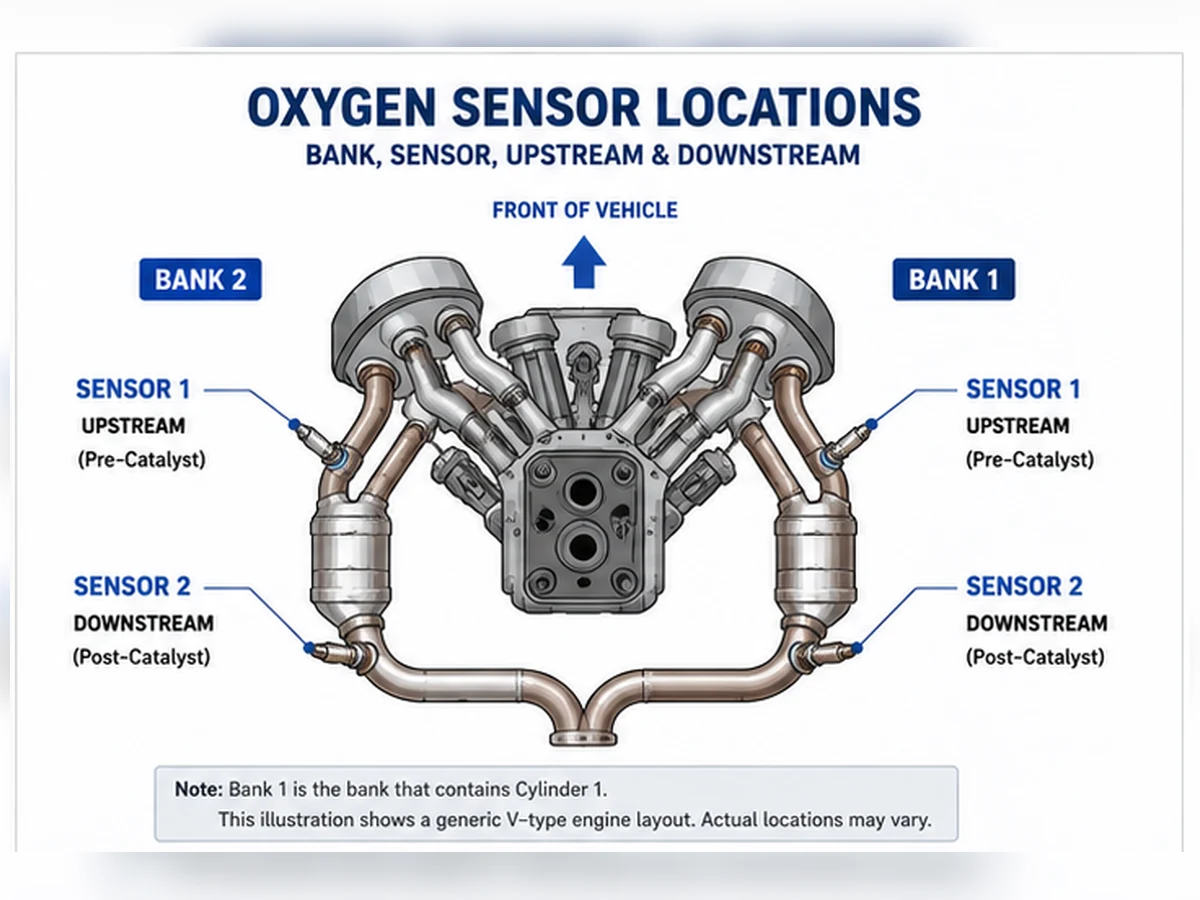
تسمية الأمامي والخلفي والمجموعة والحساس
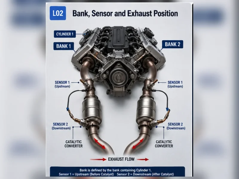
“يمكن أن يصبح ”أمامي“ و”خلفي" غامضين في المحركات العرضية أو الأنظمة التي تحتوي على عدة محفزات. استخدم تعريف البنك والمستشعر حيثما أمكن. يحتوي البنك 1 على الأسطوانة 1. المستشعر 1 هو المستشعر الموجود قبل المحفز لذلك البنك؛ المستشعر 2 هو المستشعر اللاحق. تحتوي بعض المركبات على مستشعرات إضافية أو مصطلحات مختلفة، لذا تظل معلومات الخدمة هي المرجع.
لماذا يجب أن تبدو بيانات المسح مختلفة
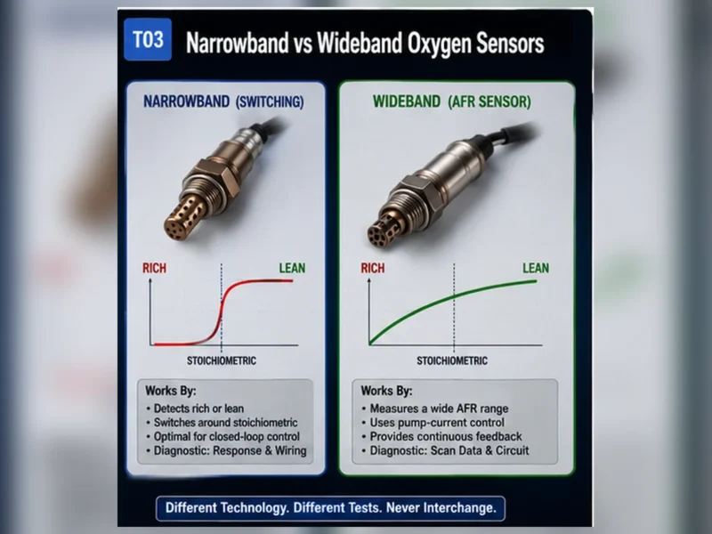
قد يتحول مستشعر النطاق الضيق التقليدي الأمامي بين الغني والفقير أثناء التشغيل في الحلقة المغلقة. يتم تمثيل مستشعر النطاق العريض بشكل مختلف وقد يظهر كتيار أو لامدا أو مكافئ موجه. يتم تفسير الإشارة اللاحقة بالنسبة لتشغيل المحفز. يمكن أن تؤدي مقارنة رسمين بيانيين دون تحديد التقنية وظروف التشغيل أولاً إلى تشخيص خاطئ.
الرموز التي تذكر موضعًا
يحدد رمز موضعي الدائرة المراد فحصها؛ لا يثبت أن عنصر الاستشعار معيب. افحص الموصل والأسلاك، طاقة وسخان التسخين والأرضي، تسرب العادم وبيانات التشغيل. لا ينبغي التعامل مع P0420 أو P0430 كتعليمات لاستبدال المستشعر اللاحق.
هل يمكن تبديل حساسات المنبع والمصب؟
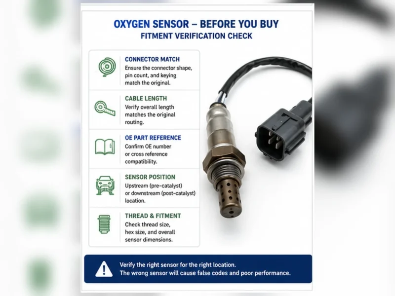
لا تفترض قابلية التبادل. قد يشترك مستشعران في حجم اللولبة أو مظهر الموصل لكن يختلفان في التقنية، المعايرة، طول الكابل، الغطاء الواقي أو تثبيت الموصل. طابق المرجع الأصلي والمركبة والمحرك وحزمة السوق/الانبعاثات والبنك والموضع بالضبط.
قائمة التحقق من التحقق من الموضع
- اقرأ وصف الكود الكامل وبيانات الإطار المتجمد.
- حدد الأسطوانة 1 والمجموعة 1 من معلومات الخدمة.
- Trace exhaust flow to distinguish pre-cat and post-cat positions.
- Compare the connector, cable length and routing clips.
- Confirm the OE reference and sensor technology before ordering.
هوية الموضع تأتي قبل تفسير الإشارة
Upstream and downstream describe location relative to a catalyst, not a universal physical direction on the vehicle. On a two-bank engine, each bank can have its own Sensor 1 and Sensor 2. Some exhaust systems add more catalysts or sensors. Confirm cylinder numbering, trace the exhaust path and match the code or data identifier to the physical connector before testing.
| Identity input | Upstream decision | Downstream decision |
|---|---|---|
| Cylinder and bank | Locate Sensor 1 on the bank containing the named cylinders | Locate Sensor 2 after that bank’s monitored catalyst |
| Exhaust flow | Before the relevant catalyst | After the relevant catalyst |
| Catalog data | Must list exact bank/position and technology | Must list exact position, lead routing and connector |
| Service diagram | Confirms physical connector and harness route | Prevents confusion with additional post-catalyst sensors |
كيف تختلف أدوار التحكم الخاصة بها
Upstream feedback
After enable conditions are met, the control module uses upstream feedback with airflow, load, temperature and other inputs to evaluate mixture. A narrowband sensor may switch around its control point, while a wideband sensor may be represented as current, lambda or equivalence ratio. A lean report can be accurate evidence of unmetered air or low fuel delivery rather than a failed sensor.
Downstream monitoring
The downstream sensor commonly helps the control module evaluate catalyst oxygen-storage behavior. Its signal is interpreted in relation to the upstream signal and defined monitor conditions. A rear sensor is not simply expected to show one fixed voltage, and a catalyst code does not prove that the rear sensor should be replaced.
Strategy exceptions
Manufacturers may use downstream information for additional adaptations or diagnostics. The common roles provide orientation, not permission to generalize one vehicle’s logic to another. Use exact service information for the vehicle, engine, emissions package and calibration.
قارن الإشارات فقط في ظل ظروف صالحة
| الحالة | Upstream observation | Downstream observation | قيد |
|---|---|---|---|
| بدء التشغيل البارد | May not yet provide closed-loop feedback | Catalyst monitor usually not ready | Temperature and enable criteria not met |
| Warm steady operation | Technology-specific mixture response | Evaluated against catalyst behavior | Leaks and fuel faults can distort both |
| Acceleration | Commanded enrichment may change the signal | Response can be delayed by catalyst storage | Not a steady-state comparison |
| Deceleration fuel cut | قد يكون متوقعًا وجود أكسجين عالٍ في العادم | Response depends on catalyst and strategy | Do not label expected behavior a fault |
استخدم رموزًا خاصة بالمواقع كمسارات اختبار
Sensor 1 circuit or response codes
Inspect the named bank and upstream circuit, but also evaluate real mixture conditions. Check connector integrity, heater operation, reference or signal ground, exhaust leaks ahead of the sensor and fuel trims. A response test must match narrowband or wideband technology.
Sensor 2 circuit or heater codes
Confirm the post-catalyst connector and harness, which may be exposed to underbody heat, water and impact. Test supply, control and signal circuits as specified. Do not substitute a catalyst-efficiency diagnosis for a direct circuit test.
P0420 and P0430
These codes concern catalyst-system efficiency. Confirm there is no active misfire, mixture fault or exhaust leak, validate both sensor signals and follow the catalyst procedure. Replacing the downstream sensor is justified only when its own evidence shows it cannot report correctly.
لماذا لا تجعل الخيوط المتطابقة المواقع قابلة للتبادل
Upstream and downstream sensors may differ in sensing technology, calibration, heater characteristics, protective shield, connector pin assignment, cable length and clips. Even when one part physically screws into both bungs, the control module may expect a different electrical system. Do not extend, force or cut a direct-fit harness to make the wrong position reach.
| Comparison item | Evidence required | Reject when |
|---|---|---|
| OE reference | Current application record for exact position | Cross-reference is unverified or for another emissions variant |
| التقنية | Narrowband, wideband/A/F or specified design | Listing relies only on wire count |
| موصل | Keying, latch and circuit assignment | Housing is forced or pins differ |
| Lead and clips | Correct length and heat-safe routing | Cable must be stretched or left near moving/hot parts |
سيناريو مركب: يتم تشخيص رمز خلفي في الموصل الأمامي
Composite engineering scenario: a technician follows a generic “rear sensor” label on a transverse engine and tests the wrong connector. The service exhaust diagram shows that the named Bank 1 Sensor 2 connector routes to a different side of the engine bay. Correct position identification changes the circuit result and prevents replacement of a functioning sensor. This is a composite teaching scenario, not a Sunhyings customer case.
سجل الموقع قبل الطلب
Capture the complete code description, engine identity, market/emissions package, cylinder 1 location, bank, sensor number, catalyst relationship, OE number, connector face and cable route. A photo should show context as well as the plug. This record lets a seller or repairer verify the exact position without turning “front” or “rear” into a fitment claim.
تحقق من الإصلاح دون فرض استنتاج
After a circuit, sensor, exhaust or engine repair, check the physical installation first. Confirm that the correct connector is locked, the cable is clipped away from heat and movement and no exhaust leak is present. Then observe the correct upstream or downstream data identifier under the operating conditions specified by the manufacturer. The signals should be interpreted together with fuel trims, commanded state and monitor status.
A downstream waveform that becomes steadier is not by itself proof that a catalyst is healthy, just as an upstream waveform that changes is not proof that the sensor is calibrated correctly. The monitor must run under valid conditions and the original fault must not return. Permanent codes may remain until the module observes a passing monitor; repeatedly clearing memory can delay rather than accelerate confirmation.
When both positions show unusual data
When upstream and downstream readings both appear abnormal, look for causes that affect the entire exhaust path: misfire, incorrect fuel delivery, exhaust leakage, temperature problems or unsupported scan-tool parameters. Replacing both sensors together may remove useful evidence and still leave the shared root cause.
When only one position has an electrical fault
A position-specific open, short or heater fault should be traced with the correct wiring diagram. Check shared supplies without assuming that every sensor uses the same fuse or ground. Load-test suspect circuits and protect terminal fit. A code naming one sensor still does not establish that the replaceable element is the failed point.
المنبع والمصب عبر تخطيطات العادم الشائعة
Upstream means before the catalyst being monitored; downstream means after it. The words do not guarantee that a sensor is physically at the front or rear of the vehicle. Packaging can place a pre-catalyst sensor behind the engine, and some systems use close-coupled catalysts plus additional underfloor catalysts. Trace exhaust flow and use exact service information.
| Layout | Typical upstream identity | Typical downstream identity | Identification risk |
|---|---|---|---|
| Inline engine, one monitored catalyst | Sensor 1 before catalyst | Sensor 2 after catalyst | Additional sensors or catalyst stages can change the count |
| V engine, separate bank catalysts | B1S1 and B2S1 before their bank catalysts | B1S2 and B2S2 after their bank catalysts | Bank 1 is defined by cylinder 1, not a universal side |
| Close-coupled plus underfloor catalyst | Sensor before the relevant monitored catalyst | One or more sensors can follow different catalyst stages | “Rear” may not uniquely identify Sensor 2 or Sensor 3 |
| Single exhaust after two banks merge | Bank-specific sensors may be upstream of merge | A shared downstream sensor may monitor the combined path | Bank naming and physical pipe count do not always match intuition |
| Transverse engine with tight packaging | Can face firewall or radiator depending on cylinder/exhaust layout | May be below catalyst or underbody | Driver/passenger and front/rear shorthand can be wrong |
دور التحكم: تغذية راجعة للخليط مقابل مراقبة المحفز
An upstream sensor commonly provides the fast mixture feedback used after closed-loop enable conditions are met. A downstream sensor commonly contributes to catalyst oxygen-storage monitoring. These are dominant roles, not universal permission to ignore service strategy. Some control systems use downstream information for adaptation or additional diagnostics.
| Decision point | قبل المحول / قبل الحفاز | بعد المحول / بعد الحفاز |
|---|---|---|
| Main question | What does exhaust oxygen indicate about mixture feedback? | How does gas behavior after the catalyst compare under monitor conditions? |
| Common technology | Narrowband or wideband/A/F depending on application | Often narrowband, but application evidence controls |
| Response expectation | Technology-specific and generally responsive to mixture changes | Interpreted with catalyst storage and upstream behavior |
| Major confounders | Intake/fuel/ignition faults, pre-sensor leak, circuit and temperature | Upstream faults, catalyst condition, leaks, mixture, circuit and monitor state |
| Replacement error | Ordering by “front” without bank/technology | Replacing because P0420/P0430 is present |
تتغير تفسير الإشارة حسب التقنية وحالة التشغيل
A warm zirconia narrowband upstream sensor may switch around its control point during closed-loop correction. A wideband/A/F sensor may be displayed as pump current, lambda, equivalence ratio or a manufacturer-derived value. The two should not be judged by the same voltage pattern. A rear narrowband signal is shaped by catalyst oxygen storage and monitor strategy, so a fixed-voltage myth is also unsafe.
| Operating state | Upstream observation | Downstream observation | Interpretation boundary |
|---|---|---|---|
| بدء التشغيل البارد | May not yet provide active feedback | Catalyst monitor normally not ready | Heater and temperature enable conditions matter |
| Warm idle | Mixture feedback may be active | Low flow and small leaks can affect reading | Idle alone is an incomplete system test |
| Steady cruise | Fuel correction and response can be evaluated | Catalyst comparison may be meaningful when enabled | Speed, load and temperature must be stable |
| Acceleration | Commanded enrichment can change the signal | Response may be delayed by catalyst storage | Not a steady-state catalyst comparison |
| Deceleration fuel cut | High exhaust oxygen can be expected | Behavior depends on storage and strategy | Expected event should not be labeled a fault |
خريطة تشخيصية خاصة بالموقع
| Concern | Upstream test emphasis | Downstream test emphasis | Shared checks |
|---|---|---|---|
| إشارة منخفضة/عالية | Actual mixture, fuel trims and reference circuit | Signal circuit, leaks and post-catalyst context | Connector, technology and exact position |
| استجابة بطيئة | Valid rich/lean stimulus and response specification | Monitor procedure and catalyst influence | Temperature, contamination and scan-data limits |
| Heater code | Protected supply/control and upstream harness route | Underbody harness exposure and shared supply | Loaded testing, pins and specified resistance/current |
| P0420/P0430 | Mixture control and upstream validity | Rear-sensor validity within catalyst path | Misfire, leaks, contamination and catalyst procedure |
| ضعف الاقتصاد في استهلاك الوقود | Potential direct effect through biased feedback | Usually not the first fuel-control suspect | Confirm actual fuel use and competing causes |
لماذا قد تبدو الأجزاء العلوية والسفلية متشابهة ولكنها تبقى غير قابلة للتبديل
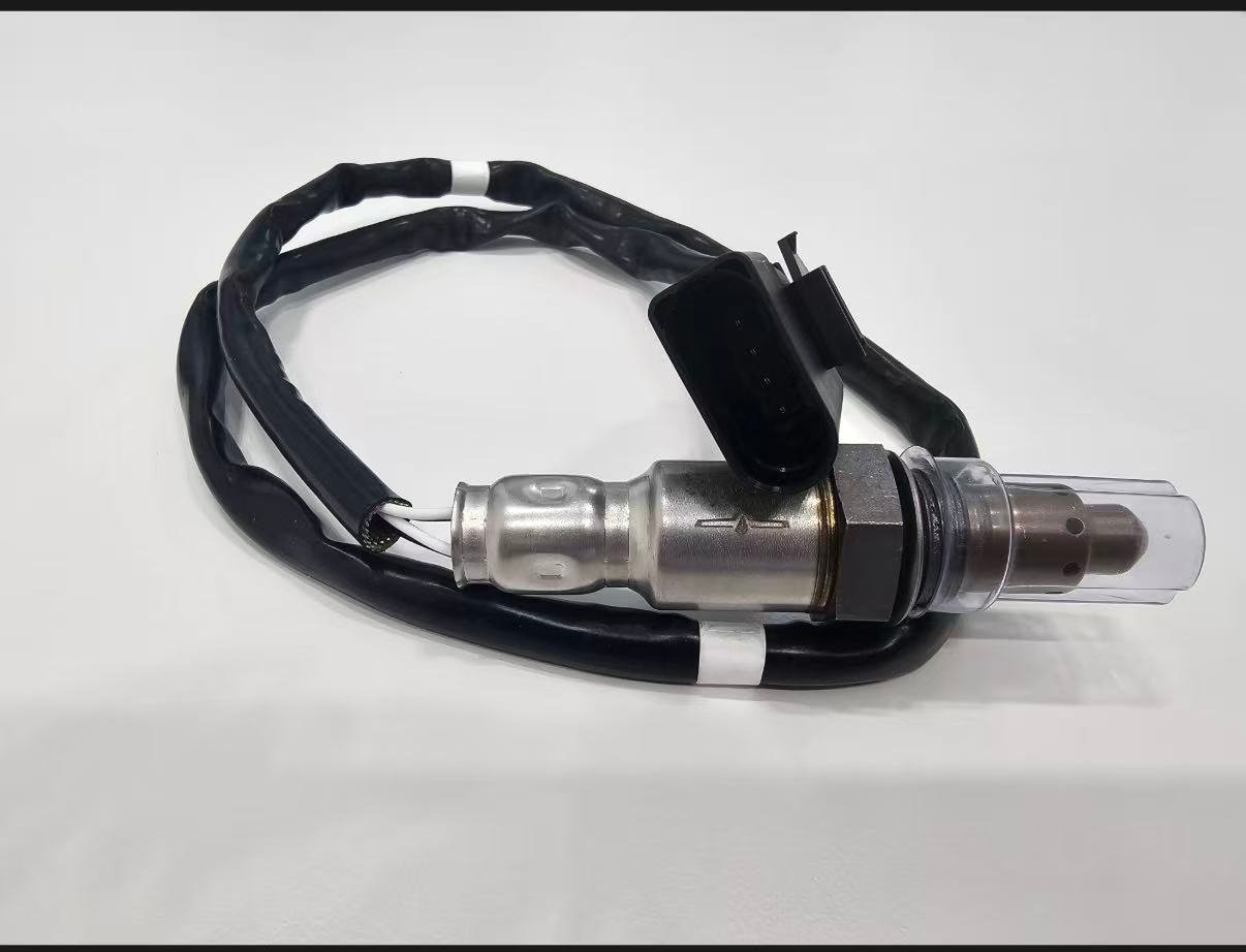
Two sensors can share the same thread and even a similar shell while differing in sensing technology, calibration, heater, connector keying, terminal assignment, lead length, clips and shield. A longer cable is not automatically a safe substitute; unmanaged cable can touch exhaust or moving components. A shorter cable must never be stretched or extended to make the wrong position reach.
| Identity feature | Evidence required | Unsafe shortcut |
|---|---|---|
| OE/application mapping | Current source for exact vehicle, engine and position | One cross-reference copied without revision |
| التقنية | Product and vehicle specification | Counting wires |
| Connector/pinout | Key, pins, terminal arrangement and circuit | Connector color or forced fit |
| Lead and clips | Length and approved route for exact position | Extending, cutting or tying excess near heat |
| Shield/thread | Drawing or verified physical specification | Assuming common thread proves interchange |
حالة مركبة: تم تخصيص موصلين متشابهين لمواقع خاطئة
Composite workshop scenario: after exhaust work, a vehicle sets position-specific response codes. Both sensors are present and their connectors can be routed to nearby branches. The technician reconciles wire colors, connector identifiers and service routing and finds the connectors crossed. Restoring the correct physical-to-data mapping resolves the conflict without replacing sensors.
The scenario shows why scan labels, physical position and connector route must agree before data is interpreted. It is a composite pattern, not a Sunhyings customer repair.
حالة مركبة: لم يكن المستشعر السفلي هو الحل التلقائي لرمز P0420
سيناريو تشخيصي مركب: a rear sensor graph appears active and a catalyst code is stored. Before ordering a rear sensor, the workshop finds an exhaust leak ahead of it and abnormal upstream fuel correction. The leak and mixture fault are corrected, exact sensors are verified and the catalyst monitor is rerun. A part decision is deferred until the system can be tested under valid conditions.
This does not promise that repairing a leak will correct every catalyst code. It shows the evidence order required before a downstream sensor or catalyst is condemned.
سجل طلب خاص بالموقع
- VIN/YMME, engine and market/emissions configuration
- Cylinder 1 source, bank identity and complete Sensor number
- Position relative to the exact monitored catalyst
- OE reference and controlled cross-reference revision
- Narrowband, titania or wideband/A/F technology
- Connector face, keying, pins, lead length, clips, thread and shield
- Diagnostic evidence that supports replacing that position
تصميم اختبار استجابة يجيب على سؤال خاص بالموقع
Before testing, state the question. For an upstream sensor it may be whether the reported mixture follows a controlled rich/lean change within the vehicle specification. For a downstream sensor it may be whether the circuit is responsive and whether its behavior is plausible during a defined catalyst monitor. The stimulus, expected parameter, time scale and pass limit must match sensor technology and service information.
| Test design field | Upstream example | Downstream example | Invalid shortcut |
|---|---|---|---|
| ظروف التشغيل | Warm closed loop at specified speed/load | Catalyst monitor enable conditions | Cold idle screenshot |
| Data channel | Correct voltage/current/lambda item | Named rear-sensor item and upstream reference | Unlabeled generic graph |
| Stimulus | Approved controlled mixture change | Manufacturer monitor or defined response procedure | Random throttle snapping |
| Confounder checks | Leaks, fuel pressure, airflow and trims | Leaks, upstream validity, misfire and catalyst state | Assuming every change comes from sensor |
| الخلاصة | Pass/fail against exact specification | Continue circuit/sensor/catalyst path | “Looks slow” without scale or limit |
When a scan tool derives or filters a parameter, document the tool and data label. If the vehicle does not support the needed information, use the OEM test method rather than inventing a universal substitute. Do not introduce fuel or air changes in a way that creates unsafe exhaust temperature or uncontrolled operation.
يغير الموقع التعرض الحراري والتوجيهي
Upstream sensors can see higher and faster-changing exhaust temperature. Downstream sensors often have longer underbody routes exposed to water, road debris and harness movement. These tendencies help plan inspection but do not replace application drawings. Verify heat shields, grommets, clips and connector location for the exact vehicle.
| Exposure | Possible upstream concern | Possible downstream concern | سجل الفحص |
|---|---|---|---|
| Heat | Manifold/catalyst proximity and rapid cycling | Radiant exhaust heat and missing shields | Full installed route and clearance photos |
| Water/debris | Connector sealing in engine compartment | Underbody impact, salt and water entry | Seal, terminal and loom condition |
| الحركة | Engine movement and tight lead | Exhaust movement and long unsupported lead | Strain relief and every clip location |
| Service access | Restricted manifold or shield access | Lift/support and corroded bung access | Access plan and thread condition |
يجب أن يحافظ دليل المورد على هوية الموضع
A distributor should not collapse upstream and downstream coverage into one marketing family without controlled part-level records. Each sellable part needs a revision, OE/application mapping, technology, connector and lead specification, validation scope, production controls and traceability. A quality-management certificate can support process-system review only within its named legal entity, site and scope; it does not prove the exact part fits both positions.
| Supplier record | Position question it must answer | Reject or hold signal |
|---|---|---|
| Application table | Which vehicle/engine/emissions/bank/sensor rows are approved? | Model-level list with no position |
| Product drawing | Are connector, lead, clips, thread and shield position-correct? | Generic family photo only |
| Electrical specification | Does technology/heater/circuit match position strategy? | Wire count used as compatibility proof |
| Validation report | Which identified samples and conditions were tested? | Test names with no criteria, results or sample identity |
| Change notice | Will position-critical design/data changes trigger review? | Uncontrolled connector, cable or catalog substitution |
تحليل لعدم تطابق مشتبه به بين المنبع والمصب
Preserve the delivered label and lot, exact vehicle identity, installed position, OE mapping source, old/new comparison and diagnostic results. A complaint that the lead is short or the connector differs can indicate a packing error, catalog error, wrong position or an unrecorded emissions variant. A returning DTC can instead reflect vehicle circuit or root-cause issues. Investigate both product conformity and application accuracy.
Do not alter the direct-fit harness to make a disputed part install. Keep the sensor clean, document connector face and route, and pause until the part record and vehicle evidence agree. This protects the customer and preserves evidence for corrective action.
شجرة قرارات المنبع/المصب من الشكوى إلى الإصلاح الموثق
- Define the complaint. Record drivability, fuel-use, warning-lamp or inspection concern under repeatable operating conditions.
- Capture system evidence. Read all modules and preserve code status, freeze frame, readiness and related misfire or fuel-control information.
- Name the position. Use engine cylinder numbering and the exhaust diagram to map bank, sensor number, catalyst and physical connector.
- Identify technology. Determine whether the named position is narrowband, titania or wideband/A/F and select supported data and tests.
- Check circuit and context. Inspect loaded heater supply/control, signal/reference integrity, exhaust leaks, trims and competing engine causes.
- Run a valid response test. Meet temperature and control-state requirements and document stimulus, units, time scale and result.
- Separate sensor from catalyst logic. For rear-sensor or P0420/P0430 concerns, prove upstream validity and follow the catalyst path.
- Select the exact part. Match OE/application, position, technology, connector, lead, clips, thread and shield.
- Install without altering the emissions system. Follow safety, torque, thread-treatment and routing instructions; retain all shields.
- Verify the original question. Recheck circuit/response and complete the applicable legal monitor under documented conditions.
If evidence conflicts at any step, stop the parts decision and resolve the conflict. For example, if the catalog says downstream but the connector route reaches the pre-catalyst bung, neither source should be silently preferred. Check the VIN/configuration, catalog revision, removed part and service diagram and record the resolution.
ادعاءات تجارية لا يدعمها هذا المقارنة
This guide does not establish that Sunhyings stocks every upstream or downstream sensor, that one part fits all positions, or that replacing a sensor will reduce emissions or fuel use by a fixed percentage. It does not publish unverified OE numbers, torque values, prices, MOQ, lead times or approvals. Those details require a part-specific quotation and evidence review.
The valid commercial invitation is to submit a controlled application and product request. Buyers should include sales market, OE/part list, YMME/engine/emissions and position data, expected quantity, packaging, validation and document requirements. Only confirmed project information should enter a quotation or product page.
For a retail request, the minimum useful submission is smaller but still exact: VIN or full YMME/engine, emissions market, Bank/Sensor position, readable old-part number and connector/lead photos. A trouble code or the words “upstream sensor” cannot substitute for those fitment inputs.
Keep the evidence with the order: catalog revision, submitted vehicle data, selected position and comparison photographs. If the delivered connector or lead conflicts with the record, stop before installation and resolve the mapping. This is safer and more useful than modifying a direct-fit part.
قم بإعداد طلب تركيب أو توريد
أرسل رقم OE، السنة/الماركة/الموديل، المحرك أو تفاصيل VIN، السوق وحزمة الانبعاثات، موضع البنك/الحساس بالضبط، صور الموصل والقطعة القديمة، الكمية وأي متطلبات تغليف أو موافقة. ستراجع Sunhyings البيانات المقدمة من حيث القدرة وجدوى التوريد؛ لا يتم تأكيد التركيب حتى يتم مطابقة دليل التطبيق.
الأسئلة المتكررة
هل المستشعر 1 في اتجاه المنبع أم المصب؟
عادةً ما يكون المستشعر 1 في المنبع من المحول الحفاز للبنك الخاص به. يُرجى تأكيد معلومات خدمة المركبة لأن تخطيطات النظام تختلف.
هل المستشعر 2 هو مستشعر الأكسجين الخلفي؟
المستشعر 2 هو عادةً المستشعر السفلي أو ما بعد المحفز، ولكن استخدم مخطط البنك والخدمة بدلاً من الاعتماد فقط على وصف الأمامي أو الخلفي.
هل يمكنني استخدام حساس في اتجاه المنبع في اتجاه المصب؟
فقط إذا كان الكتالوج المعتمد أو المرجع التقاطع الأصلي يدرج القطعة الدقيقة لكلا الموضعين. التشابه في المظهر لا يثبت قابلية التبادل.
هل يتحكم المستشعر النهائي في الوقود؟
دورها الرئيسي هو عادة مراقبة المحفز، على الرغم من أن استراتيجيات التحكم تختلف. لا تعمم منطق مركبة واحدة على جميع المركبات.
هل يعني الرمز P0420 فشل الحساس السفلي؟
الرقم P0420 يتعلق بكفاءة نظام المحفز. قم بتشخيص بيانات الحساس، سلامة نظام العادم وتشغيل المحفز قبل استبدال الأجزاء.