








Oxygen Sensor Technical Guide
Review ten possible bad oxygen sensor symptoms, the faults that can imitate them, and the checks needed before replacing an O2 sensor.

Quick answer
Common signs associated with a bad oxygen sensor include a check-engine light, poor fuel economy, rough idle, hesitation, failed emissions inspection, unusual exhaust odor, black smoke, misfire-like operation, weak acceleration and reduced engine performance. None of these symptoms proves the sensor is bad. Wiring, exhaust leaks, air and fuel faults, ignition problems and catalyst faults must be separated before replacement.
Ten signs that justify diagnosis
| Possible sign | Why an O2 sensor may be involved | Other causes to check |
|---|---|---|
| 1. Check-engine light | The control module detects a circuit, heater or response fault. | Harness damage, connector corrosion, fuse, exhaust leak or mixture fault. |
| 2. Poor fuel economy | A biased signal may drive incorrect fuel correction. | Tire pressure, driving pattern, thermostat, MAF/MAP data, injectors or fuel pressure. |
| 3. Rough idle | Incorrect feedback can destabilize mixture control. | Vacuum leak, ignition fault, injector imbalance or mechanical condition. |
| 4. Hesitation | Slow or biased feedback may affect correction during transitions. | Airflow, throttle, ignition, fuel-delivery or transmission issues. |
| 5. Failed emissions test | Fuel-control or catalyst-monitor data may be abnormal. | Catalyst, evaporative, ignition, air/fuel or readiness-monitor issues. |
| 6. Black smoke | A false lean report can contribute to excessive fueling. | Injector leakage, fuel pressure, airflow data or coolant-temperature signal. |
| 7. Poor acceleration | Incorrect mixture feedback may reduce response. | Restricted exhaust, ignition, fuel supply or load-sensor faults. |
| 8. Fuel smell | Rich operation can leave unburned fuel in the exhaust. | Fuel leak or misfire; treat an external fuel odor as a safety issue. |
| 9. Misfire-like operation | Mixture errors can aggravate combustion instability. | Plugs, coils, injectors, compression or timing. |
| 10. Reduced performance | The control strategy may use fallback values after a detected fault. | Many engine, transmission and exhaust restrictions can feel similar. |
A fault code is a starting point, not a verdict
P0130–P0167 family codes can identify a circuit, heater, activity or response problem. They do not automatically identify the failed part. P0420 and P0430 primarily concern catalyst-monitor efficiency and should not be converted into an oxygen-sensor parts order without further testing.
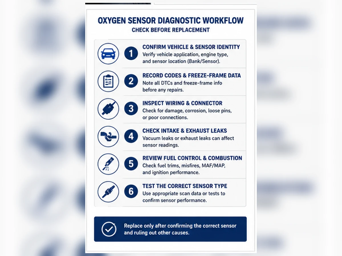
A practical pre-replacement workflow
- Record all codes, freeze-frame data and readiness status before clearing anything.
- Confirm the exact bank and sensor position from service information.
- Inspect the connector, routing, heat damage and exhaust leaks.
- Check heater supply, ground and circuit integrity as specified.
- Review fuel trims and sensor data under the required operating conditions.
- Correct root causes, then verify the monitor or drive cycle legally and safely.
When to stop driving or seek professional help
A flashing warning light, strong fuel odor, severe misfire, overheating catalyst, loss of power in traffic or damaged wiring near hot exhaust components requires prompt professional attention. Continued operation can create safety risks or damage the catalyst. Do not use spacers, simulators or software defeat strategies to hide an emissions fault.
Only order after the identity check
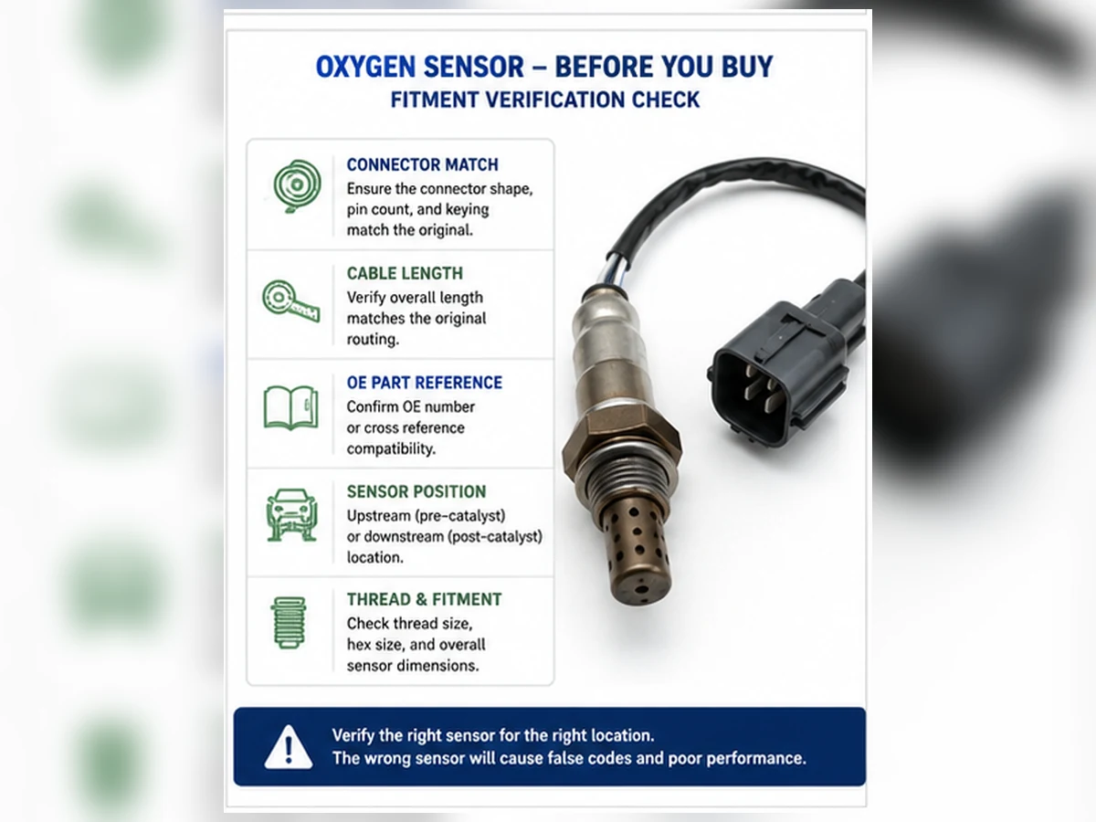
Once testing supports replacement, match the OE reference and verify year, make, model, engine, market/emissions package, bank, sensor number, connector keying, pin count and cable length. A connector that plugs in is not proof of correct calibration or position.
Group symptoms by the evidence they provide
The ten signs above are not equally specific. A warning light with a position-specific heater code gives a clearer circuit starting point than “the car uses more fuel.” A flashing warning light with active misfire is more urgent than a stored slow-response code with no drivability complaint. Organizing symptoms by diagnostic value prevents the loudest complaint from replacing evidence.
| Evidence group | Examples | What it changes |
|---|---|---|
| Electrical or circuit evidence | Heater code, open circuit, implausible fixed signal | Prioritize power, ground, continuity, connector and control tests. |
| Mixture evidence | Fuel-trim codes, rich/lean exhaust behavior, black smoke | Check air, fuel, ignition, mechanical and exhaust causes with sensor response. |
| Catalyst-monitor evidence | P0420/P0430, front/rear waveform relationship | Evaluate engine condition, leaks, sensor accuracy and catalyst together. |
| General drivability | Rough idle, hesitation, weak acceleration | Keep a broad differential diagnosis; these symptoms are not sensor-specific. |
| Operating-cost complaint | Poor fuel economy | Establish a repeatable baseline before attributing the change to one component. |
Use an evidence ladder before replacement
Level 1: complaint and warning status
Record exactly when the symptom occurs: cold start, warm idle, steady cruise, acceleration, deceleration or under load. Note whether the malfunction indicator is steady or flashing and whether other safety symptoms are present. “Runs badly” is not a reproducible test condition.
Level 2: codes, freeze frame and monitor status
Read current, pending and permanent codes before clearing them. Freeze frame records engine state when a monitor detected the fault. Readiness status shows whether the relevant monitor has completed. Multiple codes can reveal a shared power supply, air/fuel problem or misfire that a single-code view would miss.
Level 3: physical and circuit inspection
Inspect connector locks, terminal condition, harness contact with the exhaust, missing clips, oil or coolant contamination and leaks ahead of the sensor. For heater faults, use the correct circuit diagram and test supply, ground and control. Do not probe terminals in a way that spreads or damages them.
Level 4: operating data
Confirm engine temperature and control state, then compare short- and long-term fuel trims, airflow or load data, commanded mixture and the correct sensor parameter. A narrowband voltage trace and a wideband current or lambda value require different interpretation.
Level 5: controlled confirmation
Follow the manufacturer’s response or circuit procedure. A controlled test should show whether the signal changes in the expected direction and time. The method must be safe and application-specific; do not create fuel or vacuum hazards merely to force a reading.
What live data can reveal
| Observation | Possible interpretation | What prevents a conclusion |
|---|---|---|
| Positive fuel trim with lean sensor indication | Real unmetered air, low fuel delivery, exhaust leak or biased sensor | No leak, fuel-pressure or response evidence yet |
| Negative fuel trim with rich indication | Injector leakage, excessive pressure, airflow error or biased sensor | No fuel, purge or temperature checks yet |
| Flat signal | Open circuit, missing heater function, unsupported PID or failed element | Operating temperature and circuit status unknown |
| Slow response | Aged/contaminated sensor or slow mixture change | No controlled response test |
| Rear signal resembles front signal | Catalyst-system concern | Leaks, misfire, sensor bias and monitor conditions not excluded |
Composite scenario: the sensor is blamed for an intake leak
Composite engineering scenario: a vehicle has rough idle, a lean code and high positive fuel trim at idle. The upstream sensor reports lean. Fuel trim improves as engine speed rises, and a leak test identifies unmetered air near the intake. The sensor was reporting the exhaust condition correctly. Replacing it would not have sealed the leak.
Composite scenario: a new sensor does not fix the heater code
Composite engineering scenario: a heater code returns after a sensor replacement. Circuit testing shows no supply voltage because the harness touched a hot exhaust shield and opened the protected circuit. Repairing the harness, restoring routing and verifying the fuse resolves the circuit condition. The first replacement was not supported by a complete power-and-ground test.
These scenarios combine common diagnostic patterns. They are not Sunhyings customer cases, test records or claims about a specific vehicle.
Deposits can be evidence of another failure
| Observed condition | Possible source to investigate | Repeat-failure risk |
|---|---|---|
| Oily deposits | Oil consumption, valve-guide, ring or ventilation issue | A replacement sensor may contaminate again. |
| Coolant-related deposits | Internal coolant leak or combustion-chamber entry | Catalyst and new sensor can be damaged. |
| Silicone-like poisoning | Unsuitable sealant, additive or contamination source | Signal can remain biased until the source is removed. |
| Soot / rich deposits | Fuel, ignition, airflow or temperature-control fault | Replacing the reporter does not correct rich operation. |
Repair decision: sensor, circuit or root cause?
- Replace the sensor when the specified circuit and response tests show the element or integrated heater cannot meet requirements.
- Repair the circuit when power, ground, connector, terminal or harness integrity is the fault.
- Repair the engine or exhaust condition when the sensor correctly reports a real mixture or leakage problem.
- Continue catalyst diagnosis when a catalyst-monitor code remains after engine, exhaust and sensor evidence is validated.
After repair, restore harness routing and heat protection, verify the relevant live data and complete the legal monitor procedure. Clearing a code is an administrative action, not proof that the symptom or root cause is gone.
Why symptom-based shopping creates returns
Search terms such as “rough idle O2 sensor” describe a complaint, not a part identity. A responsible seller or distributor should request the OE number, full vehicle and engine data, region/emissions package, bank and position, connector photos and diagnostic basis. If the evidence is incomplete, the correct response is a fitment review—not a guaranteed-fit claim.
Triage symptoms by safety and damage risk
| Condition | Recommended response | Reason |
|---|---|---|
| Flashing malfunction indicator, severe shaking or active misfire | Reduce risk and obtain prompt professional diagnosis; do not continue normal driving. | Unburned fuel can overheat and damage the catalyst, and power loss can create a traffic hazard. |
| Strong raw-fuel odor or visible fuel leak | Stop and treat it as a safety issue. | Fire and exposure risk take priority over oxygen-sensor troubleshooting. |
| Melted harness, smoke or contact with hot exhaust | Switch off safely and repair routing/circuit damage. | Short circuits and further heat damage can develop. |
| Steady warning light with normal operation | Record codes and arrange diagnosis without unnecessary delay. | The vehicle may use fallback control and emissions monitors may be incomplete. |
| Mileage change without warning or drivability symptoms | Establish a repeatable baseline and inspect general maintenance factors. | The complaint has low specificity for an oxygen sensor. |
Choose the test path from the code type
Heater-circuit codes
Confirm the correct sensor, then inspect the heater fuse or protected supply, ground/control path, connector and harness. Measure resistance or current only according to the vehicle procedure. A new sensor will not repair missing vehicle-side power, a damaged terminal or a control-module command issue.
Low, high or no-activity signal codes
Determine whether the reported limit is electrically plausible and whether the engine is truly rich or lean. Compare fuel trims, airflow, coolant temperature and exhaust integrity. Check reference ground and signal continuity. A fixed scan value can reflect wiring, an unsupported data parameter or a sensor that has not reached its operating condition.
Slow-response codes
Verify the enable criteria and sensor technology before timing a response. Contamination and aging can slow the element, but a slow change in the actual mixture, an exhaust leak or a scan tool with a low update rate can distort the observation. Use the manufacturer’s defined response test.
Catalyst-efficiency codes
Do not jump from P0420/P0430 to a rear-sensor order. Confirm there is no active misfire or fuel-control fault, inspect exhaust leakage, validate both sensor signals and follow the catalyst test. A converter damaged by an unresolved engine condition can fail again even if it is replaced.
Post-repair verification matrix
| Repair type | Immediate check | Monitor-level confirmation |
|---|---|---|
| Sensor replacement | Connector locked, cable clipped, no exhaust leak, expected heater and signal data | Relevant monitor completes without the fault returning. |
| Harness or connector repair | Continuity, terminal retention, load behavior and safe heat routing | No intermittent fault through warm-up and the required drive conditions. |
| Intake/fuel/ignition repair | Fuel trims and combustion behavior move toward expected values | Mixture and misfire monitors complete as applicable. |
| Exhaust leak repair | No leakage at the repaired joint and sensor data is plausible | Catalyst or sensor monitor runs under valid conditions. |
Permanent codes may remain until the control module confirms that the monitor passes. Do not use battery disconnection or repeated clearing to manufacture a clean screen. Record pre- and post-repair data so the decision can be audited.
Distributor content and return-prevention controls
Product listings should separate symptom education from fitment claims. State that symptoms and DTCs require diagnosis, identify whether the listing is upstream or downstream and narrowband or wideband, and publish the source and revision of application data. Require the buyer to confirm engine and position instead of selecting from a model name alone.
For returns, capture the ordered part number, claimed OE reference, full YMME/engine/market, installed position, connector photos, codes before and after installation and the reason for replacement. This evidence helps separate catalog error, installation damage, circuit fault, unresolved root cause and genuine product nonconformance.
Symptom triage: decide whether the vehicle should be driven
Symptoms do not all carry the same risk. A steady malfunction indicator with no drivability change may allow a controlled trip for diagnosis, subject to the vehicle manual and local rules. A flashing warning lamp, severe misfire, raw-fuel odor, visible smoke, loss of power, overheating catalyst area or a damaged harness near hot exhaust calls for immediate attention. Continuing to drive a severe rich or misfire condition can overheat the catalyst and turn a diagnosis into a larger repair.
Record when the symptom occurs before disconnecting the battery or clearing codes: cold start, warm idle, steady cruise, acceleration, deceleration, after refueling or only in wet weather. Note fuel level, ambient conditions and recent work. This operating context is often more useful than a generic statement that the vehicle “runs badly.”
| Observed symptom | Immediate evidence to capture | Competing causes to test | Sensor-focused check |
|---|---|---|---|
| Check-engine light | Current, pending and permanent DTCs; freeze frame; readiness | Wiring, heater supply, exhaust leak, mixture or catalyst condition | Match code family to exact bank, position and circuit |
| Poor fuel economy | Calculated fuel use over repeatable distance and conditions | Tire pressure, trip pattern, thermostat, airflow, fuel delivery, drag | Fuel trims and technology-specific response when warm |
| Rough idle | Misfire counters, trims by bank, idle speed and load | Vacuum leak, ignition, injector, compression or purge flow | Compare both banks and inspect pre-sensor exhaust leaks |
| Hesitation | Throttle, load, fuel pressure and commanded mixture during event | Fuel delivery, airflow calculation, ignition or transmission behavior | Check response under the service procedure, not by free revving alone |
| Black smoke or fuel odor | Fuel trims, misfire data, injector command and oil contamination | Leaking injector, excessive fuel pressure, purge fault or ignition failure | Determine whether a rich report is accurate before condemning the sensor |
| Failed emissions inspection | Failure report, readiness status and all stored codes | Incomplete monitors, evaporative, catalyst, misfire or fuel-control fault | Identify which monitor or circuit actually failed |
| Reduced acceleration | Load, airflow, throttle, fuel pressure and exhaust restriction evidence | Catalyst restriction, boost, ignition, fuel or transmission issue | Do not infer sensor failure from power loss alone |
| Repeated sensor replacement | Old and new part identity, position, test results and return timing | Wrong fitment, harness heat damage, contamination or unresolved engine fault | Audit the original diagnosis and application record |
Build an evidence stack instead of counting symptoms
Ten symptoms do not create ten votes for a bad sensor. Several complaints can come from one underlying rich, lean or misfire condition. A defensible diagnosis combines four evidence layers: exact vehicle and sensor identity, circuit integrity, exhaust and engine context, and a valid response test. If one layer is missing, the conclusion remains provisional.
1. Vehicle and position identity
Record year, make, model, engine, market or emissions configuration and VIN breakpoint where applicable. Identify Bank 1 from the cylinder containing number 1 and identify Sensor 1 or Sensor 2 relative to the monitored catalyst. A scan-tool label is useful only after it is reconciled with the physical connector and service diagram.
2. Circuit integrity
Inspect terminal fit, corrosion, water entry, chafing, melted insulation and tension on the lead. For heater faults, test the protected supply and control or ground under load according to the wiring diagram. An unloaded meter reading can show battery voltage through a high-resistance connection that cannot carry heater current.
3. Engine and exhaust context
Check for leaks ahead of the sensor, unmetered air, incorrect fuel pressure, injector leakage, purge flow, ignition faults and mechanical problems. Review short- and long-term fuel trims by bank and at more than one operating point. The pattern across idle and elevated load can help distinguish an air leak from a fuel-delivery or measurement problem, but exact limits remain vehicle-specific.
4. Technology-correct response
A zirconia narrowband sensor, titania sensor and wideband air-fuel-ratio sensor do not share one universal voltage test. A scan tool may display wideband information as current, lambda, equivalence ratio or a manufacturer-derived value. Use the correct data item and service procedure, allow the sensor to reach operating temperature and verify that the engine can actually be driven rich and lean before judging response.
Read symptom patterns across banks and operating states
| Pattern | What it can suggest | Why it is not proof | Next comparison |
|---|---|---|---|
| Both banks lean mainly at idle | Shared unmetered-air source | Fuel delivery or reporting errors can overlap | Compare trims at higher airflow and inspect intake/purge paths |
| One bank lean at idle and load | Bank-specific leak, injector or exhaust issue | A wiring or sensor bias can create a similar report | Compare bank signals, leak evidence and cylinder data |
| Rich indication with black smoke | Actual excess fuel or incomplete combustion | The sensor may be reporting correctly | Check fuel pressure, injectors, ignition and purge operation |
| Flat signal with heater code | Sensor may not reach operating temperature | Supply, fuse, wiring or control may be the cause | Perform loaded heater-circuit checks |
| Slow response after silicone or coolant exposure | Contamination may have impaired the element | Exhaust leaks and test method can also slow the graph | Correct contamination source and run specified response test |
| Rear signal resembles front signal | Catalyst oxygen-storage concern may exist | Monitor conditions, leaks, mixture faults and sensor response matter | Follow the catalyst monitor diagnostic path |
Composite workshop case: a “bad sensor” was reporting a real lean condition
Composite engineering scenario: a warm engine has rough idle, positive fuel correction and a lean code on both banks. The upstream signals respond when mixture is deliberately changed, while fuel correction becomes much smaller as engine speed and airflow rise. A controlled smoke check identifies an intake leak downstream of the airflow measurement. After the leak is repaired, trims stabilize and the monitor completes without replacing either sensor.
The decision point is not that one trim pattern proves an intake leak. It is that a shared lean condition, operating-state comparison and valid sensor response made immediate sensor replacement poorly supported. The case combines common diagnostic patterns and is not a Sunhyings customer record.
Composite fleet case: repeated heater codes followed the harness
Composite engineering scenario: a fleet vehicle receives a replacement downstream sensor after a heater DTC. The fault returns intermittently after long drives. Inspection during a static cold check finds no open circuit, but harness routing shows the lead touching a heat shield after drivetrain movement. A loaded test while moving the harness reproduces the voltage drop. Correct routing and repair of the damaged vehicle-side circuit resolve the fault.
The lesson is that a new sensor cannot correct missing power or an intermittent vehicle harness. A warranty return should include the part and lot identity, the exact installed position, before-and-after codes, circuit readings and routing photos. This scenario is composite, not evidence of a specific product failure rate.
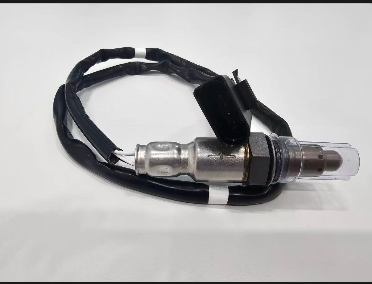
Convert a supported diagnosis into a correct order
| Order field | Acceptable evidence | Stop condition |
|---|---|---|
| OE reference | Readable removed-part number or current controlled catalog source | Marketplace cross-reference with no source or revision |
| Vehicle | YMME, engine, market/emissions and relevant VIN/build data | Model name alone |
| Position | Bank and Sensor designation reconciled to physical location | “Front” or “rear” without exhaust-layout context |
| Technology | Narrowband, titania or wideband/A/F specification | Selection by wire count alone |
| Interface | Thread, shield, connector keying, pins, lead and clips | Connector forced, cable stretched or clips omitted |
| Diagnostic basis | Failed circuit or response test after competing causes were checked | Symptom list or code number used as sole proof |
What each common symptom can and cannot tell you
Check-engine light and stored codes
The warning lamp confirms that the control system detected a monitored condition; it does not identify the physical cause. Record every code and its status because a mixture or misfire code can change how an oxygen-sensor code is interpreted. Freeze frame establishes a useful starting condition, but a single captured frame may not include the first event in the causal chain.
Fuel consumption and dashboard estimates
A short-term dashboard estimate is sensitive to idle time, traffic, temperature, fuel blend, tire pressure and driving style. Establish a repeatable baseline using actual fuel added and distance over comparable operation. If fuel correction is abnormal, determine whether the sensor is biased or accurately reporting an engine condition. Replacing a correctly reporting sensor cannot restore economy lost to an intake leak, thermostat problem, dragging brake or leaking injector.
Idle quality, hesitation and weak acceleration
These complaints can originate in ignition, fuel delivery, air measurement, variable valve control, compression, exhaust restriction or transmission behavior. Oxygen-sensor data can help explain mixture response, but it is rarely the only useful channel. Correlate the event with misfire counters, calculated load, airflow, throttle, fuel pressure or commanded equivalence ratio as supported by the vehicle.
Smoke, odor and deposit evidence
Black smoke or fuel odor raises the urgency of rich-operation and misfire checks. Blue or oil-related smoke and coolant loss point toward other engine conditions that can contaminate both sensor and catalyst. A photograph of deposits is useful for the repair record, but do not label chemistry by color alone or attempt to clean the sensing element with an unapproved solvent.
Inspection failure and incomplete readiness
An inspection can fail because a confirmed emissions fault exists or because required monitors have not completed after clearing codes or losing power. Repeatedly clearing memory can delay a valid result and conceal useful diagnostic history. Repair the cause, preserve legal emissions controls and complete the applicable drive or monitor procedure. Spacers, simulators, deletes and software monitor defeat are not repair methods.
Minimum repair and warranty record
A useful record allows another technician, distributor or supplier to reproduce the decision. It also separates wrong fitment, installation damage, unresolved vehicle faults and possible product nonconformance. Record unavailable information as DATA NOT AVAILABLE; do not turn a missing result into a passing result.
- Vehicle identity, engine, market/emissions configuration and mileage at diagnosis
- Exact sensor position and service-information basis used to identify it
- All codes, status, freeze frame, readiness and relevant live-data captures
- Wiring, loaded heater, exhaust-leak, fuel-trim and response-test results
- Old and replacement part numbers, OE mapping source, package and lot/date record
- Connector, terminals, deposits, routing and installed-clearance photographs
- Post-repair response and monitor result under documented conditions
Prepare a fitment or sourcing request
Send the OE number, year/make/model, engine or VIN details, market and emissions package, exact bank/sensor position, connector and old-part photos, quantity and any packaging or approval requirements. Sunhyings will review the supplied data for capability and sourcing feasibility; fitment is not confirmed until application evidence is matched.
Frequently asked questions
What is the most common sign of a bad oxygen sensor?
A check-engine light is common, but the code and live data must be diagnosed because wiring, mixture and exhaust faults can trigger similar warnings.
Can a bad O2 sensor cause rough idle?
It can contribute to incorrect fuel correction, but vacuum leaks, ignition faults, injectors and mechanical problems are also common causes.
Does P0420 mean the oxygen sensor is bad?
No. P0420 concerns catalyst-system efficiency. Sensor data is part of the diagnosis, but the code does not prove the sensor failed.
Can I keep driving with an oxygen sensor code?
That depends on symptoms and the fault. A flashing warning light, strong fuel odor, severe misfire or major power loss warrants immediate professional attention.
Should I replace all oxygen sensors together?
Not automatically. Test the identified circuit and replace only parts supported by diagnosis and the vehicle service procedure.