








Technischer Leitfaden für Sauerstoffsensoren
Zehn mögliche Symptome eines defekten Sauerstoffsensors, die Fehler, die diese nachahmen können, und die erforderlichen Prüfungen vor dem Austausch eines O2-Sensors überprüfen.

Kurze Antwort
Häufige Anzeichen für einen defekten Sauerstoffsensor sind eine Motorkontrollleuchte, schlechter Kraftstoffverbrauch, unruhiger Leerlauf, Zögern, nicht bestandene Abgasuntersuchung, ungewöhnlicher Auspuffgeruch, schwarzer Rauch, ruckartiger Betrieb, schwache Beschleunigung und reduzierte Motorleistung. Keines dieser Symptome beweist, dass der Sensor defekt ist. Verkabelung, Auspufflecks, Luft- und Kraftstofffehler, Zündungsprobleme und Katalysatorfehler müssen vor dem Austausch ausgeschlossen werden.
Zehn Anzeichen, die eine Diagnose rechtfertigen
| Mögliches Anzeichen | Warum ein O2-Sensor beteiligt sein kann | Andere zu prüfende Ursachen |
|---|---|---|
| 1. Motorkontrollleuchte | Das Steuermodul erkennt einen Fehler im Stromkreis, Heizgerät oder in der Reaktion. | Kabelbaum beschädigt, Steckerkorrosion, Sicherung, Abgasleck oder Gemischfehler. |
| 2. Hoher Kraftstoffverbrauch | Ein fehlerhaftes Signal kann zu einer falschen Kraftstoffkorrektur führen. | Reifendruck, Fahrverhalten, Thermostat, MAF/MAP-Daten, Einspritzdüsen oder Kraftstoffdruck. |
| 3. Unruhiger Leerlauf | Falsche Rückmeldung kann die Gemischregelung destabilisieren. | Unterdruckleck, Zündungsfehler, Einspritzdüsenungleichgewicht oder mechanischer Zustand. |
| 4. Zögern | Langsames oder verzerrtes Feedback kann die Korrektur während Übergängen beeinträchtigen. | Luftstrom, Drosselklappe, Zündung, Kraftstoffzufuhr oder Getriebeprobleme. |
| 5. Nicht bestandener Abgastest | Daten zur Kraftstoffregelung oder Katalysatorüberwachung können abnormal sein. | Probleme mit Katalysator, Verdunstung, Zündung, Luft/Kraftstoff oder Bereitschaftsüberwachung. |
| 6. Schwarzer Rauch | Ein falscher Magerbericht kann zu übermäßiger Kraftstoffzufuhr beitragen. | Einspritzdüsenleckage, Kraftstoffdruck, Luftmengendaten oder Kühlmitteltemperatursignal. |
| 7. Schlechte Beschleunigung | Falsche Gemischrückmeldung kann die Reaktion verringern. | Eingeschränkte Abgas-, Zündungs-, Kraftstoffversorgungs- oder Lastsensorfehler. |
| 8. Kraftstoffgeruch | Fetter Betrieb kann unverbrannten Kraftstoff im Abgas hinterlassen. | Kraftstoffleck oder Fehlzündung; behandeln Sie einen externen Kraftstoffgeruch als Sicherheitsproblem. |
| 9. Fehlzündungsähnlicher Betrieb | Gemischfehler können die Verbrennungsstabilität verschlechtern. | Zündkerzen, Spulen, Einspritzdüsen, Verdichtung oder Zündzeitpunkt. |
| 10. Reduzierte Leistung | Die Steuerungsstrategie kann nach einem erkannten Fehler auf Ersatzwerte zurückgreifen. | Viele Motor-, Getriebe- und Abgaseinschränkungen können sich ähnlich anfühlen. |
Ein Fehlercode ist ein Ausgangspunkt, kein Urteil
Die Fehlercodes der Familie P0130–P0167 können ein Problem mit dem Stromkreis, der Heizung, der Aktivität oder der Reaktion identifizieren. Sie identifizieren nicht automatisch das defekte Teil. P0420 und P0430 betreffen hauptsächlich die Effizienz des Katalysator-Monitors und sollten ohne weitere Prüfung nicht in eine Sauerstoffsensor-Bestellung umgewandelt werden.
Ein praktischer Arbeitsablauf vor dem Austausch
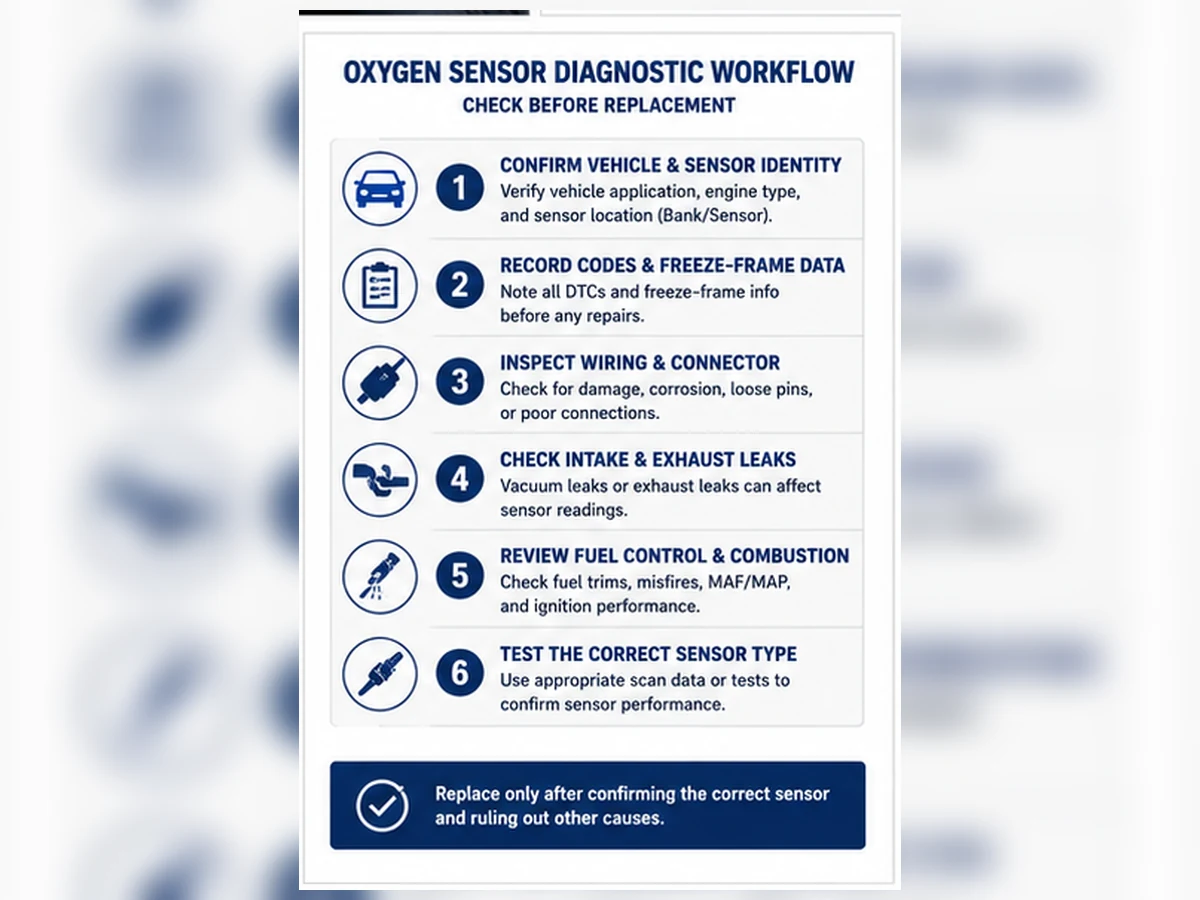
- Notieren Sie alle Codes, Freeze-Frame-Daten und Bereitschaftsstatus, bevor Sie etwas löschen.
- Bestätigen Sie die genaue Bank- und Sensorposition anhand der Serviceinformationen.
- Überprüfen Sie den Stecker, die Verlegung, Hitzeschäden und Abgaslecks.
- Überprüfen Sie die Heizungsversorgung, Masse und Schaltkreisintegrität gemäß den Vorgaben.
- Kraftstofftrimms und Sensordaten unter den erforderlichen Betriebsbedingungen prüfen.
- Grundursachen beheben, dann den Monitor oder Fahrzyklus legal und sicher verifizieren.
Wann Sie aufhören zu fahren oder professionelle Hilfe suchen sollten
Eine blinkende Warnleuchte, starker Kraftstoffgeruch, schweres Fehlzünden, überhitzter Katalysator, Leistungsverlust im Verkehr oder beschädigte Verkabelung in der Nähe heißer Abgaskomponenten erfordern sofortige professionelle Aufmerksamkeit. Weiterbetrieb kann Sicherheitsrisiken schaffen oder den Katalysator beschädigen. Verwenden Sie keine Abstandshalter, Simulatoren oder Software-Umgehungsstrategien, um einen Emissionsfehler zu verbergen.
Nur nach Identitätsprüfung bestellen
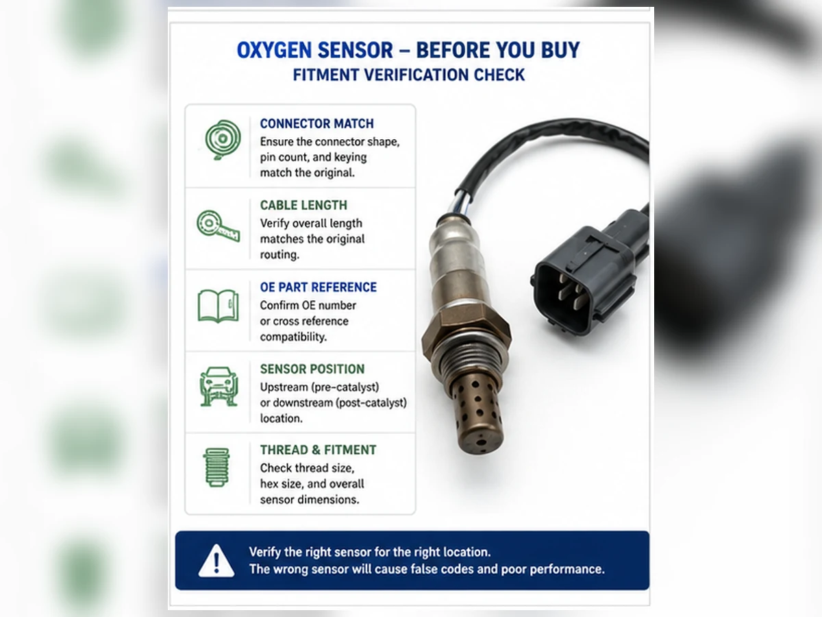
Wenn Tests den Austausch unterstützen, die OE-Referenz abgleichen und Jahr, Marke, Modell, Motor, Markt/Emissionspaket, Bank, Sensornummer, Steckerkodierung, Pin-Anzahl und Kabellänge überprüfen. Ein Stecker, der einrastet, ist kein Beweis für korrekte Kalibrierung oder Position.
Gruppieren Sie Symptome nach den Beweisen, die sie liefern
Die zehn oben genannten Anzeichen sind nicht gleich spezifisch. Eine Warnleuchte mit positionsspezifischem Heizungscode gibt einen klareren Schaltungsausgangspunkt als “das Auto verbraucht mehr Kraftstoff”. Eine blinkende Warnleuchte mit aktivem Fehlzünden ist dringender als ein gespeicherter Slow-Response-Code ohne Fahrbarkeitsbeschwerde. Die Organisation der Symptome nach diagnostischem Wert verhindert, dass die lauteste Beschwerde Beweise ersetzt.
| Beweisgruppe | Beispiele | Was sie ändert |
|---|---|---|
| Elektrischer oder Stromkreisnachweis | Heizercode, offener Stromkreis, unplausibles festes Signal | Priorisieren Sie Strom-, Masse-, Durchgangs-, Steckverbinder- und Steuertests. |
| Gemisch-Nachweis | Kraftstoffanpassungscodes, fettes/mageres Abgasverhalten, schwarzer Rauch | Überprüfen Sie Luft-, Kraftstoff-, Zündungs-, mechanische und Abgasursachen mit Sensorreaktion. |
| Katalysator-Überwachungsnachweis | P0420/P0430, Verhältnis zwischen vorderer und hinterer Wellenform | Motorzustand, Lecks, Sensorgenauigkeit und Katalysator gemeinsam prüfen. |
| Allgemeines Fahrverhalten | Unruhiger Leerlauf, Zögern, schwache Beschleunigung | Breite Differenzialdiagnose beibehalten; diese Symptome sind nicht sensorspezifisch. |
| Betriebskostenbeschwerde | Hoher Kraftstoffverbrauch | Vor der Zuschreibung der Änderung auf eine Komponente eine reproduzierbare Basislinie festlegen. |
Vor dem Austausch eine Beweiskette erstellen
Stufe 1: Beschwerde und Warnstatus
Notieren Sie genau, wann das Symptom auftritt: Kaltstart, warmer Leerlauf, konstante Fahrt, Beschleunigung, Verzögerung oder unter Last. Vermerken Sie, ob die Störungsanzeige konstant leuchtet oder blinkt und ob andere Sicherheitssymptome vorhanden sind. “Läuft schlecht” ist kein reproduzierbarer Testzustand.
Stufe 2: Codes, Freeze Frame und Monitorstatus
Lesen Sie aktuelle, anstehende und permanente Codes, bevor Sie sie löschen. Der Freeze Frame zeichnet den Motorzustand auf, als ein Monitor den Fehler erkannt hat. Der Bereitschaftsstatus zeigt an, ob der betreffende Monitor abgeschlossen ist. Mehrere Codes können ein gemeinsames Stromversorgungs-, Luft-/Kraftstoffproblem oder eine Fehlzündung aufdecken, die eine Einzelcodeansicht übersehen würde.
Stufe 3: Physische und Schaltkreisprüfung
Überprüfen Sie Steckersicherungen, Kontaktzustand, Kabelbaumkontakt mit dem Auspuff, fehlende Clips, Öl- oder Kühlmittelkontamination und Lecks vor dem Sensor. Verwenden Sie bei Heizungsfehlern den korrekten Schaltplan und testen Sie Versorgung, Masse und Steuerung. Sondieren Sie keine Anschlüsse auf eine Weise, die sie aufweitet oder beschädigt.
Stufe 4: Betriebsdaten
Bestätigen Sie Motortemperatur und Steuerungszustand, vergleichen Sie dann kurz- und langfristige Kraftstofftrimmung, Luftstrom- oder Lastdaten, befohlenes Gemisch und den korrekten Sensorparameter. Eine Schmalband-Spannungskurve und ein Breitband-Strom- oder Lambdawert erfordern unterschiedliche Interpretation.
Stufe 5: Kontrollierte Bestätigung
Befolgen Sie die Reaktions- oder Schaltkreisprozedur des Herstellers. Ein kontrollierter Test sollte zeigen, ob sich das Signal in der erwarteten Richtung und Zeit ändert. Die Methode muss sicher und anwendungsspezifisch sein; erzeugen Sie keine Kraftstoff- oder Vakuumgefahren, nur um einen Messwert zu erzwingen.
Was Live-Daten verraten können
| Beobachtung | Mögliche Interpretation | Was eine Schlussfolgerung verhindert |
|---|---|---|
| Positive Gemischregelung mit Mager-Sensoranzeige | Echte ungemessene Luft, geringe Kraftstoffzufuhr, Abgasleck oder fehlerhafter Sensor | Noch kein Hinweis auf Leck, Kraftstoffdruck oder Reaktion |
| Negative Gemischregelung mit Fett-Anzeige | Einspritzventilleckage, übermäßiger Druck, Luftmengenfehler oder fehlerhafter Sensor | Noch keine Kraftstoff-, Spül- oder Temperaturprüfungen |
| Flaches Signal | Unterbrechung, fehlende Heizfunktion, nicht unterstützte PID oder defektes Element | Betriebstemperatur und Schaltkreisstatus unbekannt |
| Langsame Reaktion | Gealterter/verunreinigter Sensor oder langsame Gemischänderung | Kein kontrollierter Reaktionstest |
| Hinteres Signal ähnelt vorderem Signal | Problem im Katalysatorsystem | Lecks, Fehlzündungen, Sensorabweichungen und Überwachungsbedingungen nicht ausgeschlossen |
Komplexes Szenario: Dem Sensor wird ein Ansaugleck angelastet
Komplexes technisches Szenario: Ein Fahrzeug hat unruhigen Leerlauf, einen Mager-Code und hohe positive Kraftstofftrim im Leerlauf. Der vorgeschaltete Sensor meldet mager. Der Kraftstofftrim verbessert sich mit steigender Motordrehzahl, und ein Lecktest identifiziert ungemessene Luft nahe dem Ansaugtrakt. Der Sensor hat den Abgaszustand korrekt gemeldet. Ein Austausch hätte das Leck nicht abgedichtet.
Komplexes Szenario: Ein neuer Sensor behebt den Heizungscode nicht
Komplexes technisches Szenario: Ein Heizungscode tritt nach einem Sensorwechsel erneut auf. Die Schaltkreisprüfung zeigt keine Versorgungsspannung, da das Kabelbaum an einer heißen Abgasabschirmung scheuerte und den geschützten Stromkreis unterbrach. Die Reparatur des Kabelbaums, die Wiederherstellung der Verlegung und die Überprüfung der Sicherung beheben den Schaltkreis-Zustand. Der erste Austausch wurde nicht durch eine vollständige Spannungs- und Masseprüfung gestützt.
Diese Szenarien kombinieren gängige Diagnosemuster. Es handelt sich nicht um Sunhyings Kundenfälle, Testaufzeichnungen oder Behauptungen über ein bestimmtes Fahrzeug.
Ablagerungen können Hinweis auf einen anderen Fehler sein
| Beobachteter Zustand | Mögliche zu untersuchende Quelle | Wiederholungsausfallrisiko |
|---|---|---|
| Ölige Ablagerungen | Ölverbrauch, Ventilführungs-, Ring- oder Belüftungsproblem | Ein Ersatzsensor kann erneut verschmutzen. |
| Kühlmittelbedingte Ablagerungen | Internes Kühlmittelleck oder Eintritt in den Brennraum | Katalysator und neuer Sensor können beschädigt werden. |
| Silikonartige Vergiftung | Ungeeignetes Dichtmittel, Additiv oder Verunreinigungsquelle | Signal kann verfälscht bleiben, bis die Quelle entfernt wird. |
| Ruß / fette Ablagerungen | Fehler in Kraftstoff, Zündung, Luftzufuhr oder Temperaturregelung | Austausch des Reporters behebt den fetten Betrieb nicht. |
Reparaturentscheidung: Sensor, Schaltung oder Ursache?
- Sensor ersetzen wenn die angegebenen Schaltungs- und Reaktionstests zeigen, dass das Element oder die integrierte Heizung die Anforderungen nicht erfüllen kann.
- Reparieren Sie die Schaltung wenn die Störung an der Stromversorgung, Masse, am Stecker, an der Klemme oder an der Kabelbaum-Integrität liegt.
- Reparieren Sie den Motor oder die Abgasbedingung wenn der Sensor korrekt ein echtes Gemisch- oder Leckageproblem meldet.
- Fahren Sie mit der Katalysatordiagnose fort wenn nach Überprüfung von Motor-, Abgas- und Sensorwerten ein Katalysator-Überwachungscode bestehen bleibt.
Stellen Sie nach der Reparatur die Kabelbaumführung und den Hitzeschutz wieder her, überprüfen Sie die relevanten Live-Daten und führen Sie das gesetzliche Überwachungsverfahren durch. Das Löschen eines Codes ist eine administrative Maßnahme, kein Nachweis dafür, dass das Symptom oder die Ursache beseitigt ist.
Warum symptomorientierter Einkauf Retouren verursacht
Suchbegriffe wie “unruhiger Leerlauf O2-Sensor” beschreiben ein Problem, keine Teilidentität. Ein verantwortungsvoller Verkäufer oder Händler sollte die OE-Nummer, vollständige Fahrzeug- und Motordaten, Region/Abgasnorm, Bank und Position, Steckerfotos und Diagnosegrundlage anfordern. Wenn die Nachweise unvollständig sind, ist die korrekte Antwort eine Prüfung der Passgenauigkeit – keine Garantie für die Passgenauigkeit.
Symptome nach Sicherheits- und Schadensrisiko priorisieren
| Zustand | Empfohlene Antwort | Grund |
|---|---|---|
| Blinkende Störungsanzeige, starkes Ruckeln oder aktive Fehlzündung | Risiko reduzieren und umgehend professionelle Diagnose einholen; nicht normal weiterfahren. | Unverbrannter Kraftstoff kann den Katalysator überhitzen und beschädigen, und Leistungsverlust kann eine Verkehrsgefahr darstellen. |
| Starker Kraftstoffgeruch oder sichtbares Kraftstoffleck | Anhalten und als Sicherheitsproblem behandeln. | Brand- und Hitzeeinwirkungsrisiko hat Vorrang vor der Fehlersuche am Sauerstoffsensor. |
| Geschmolzener Kabelbaum, Rauch oder Kontakt mit heißem Auspuff | Sicher ausschalten und Leitungs-/Stromkreisbeschädigungen reparieren. | Kurzschlüsse und weitere Hitzeschäden können entstehen. |
| Dauerhafte Warnleuchte bei normalem Betrieb | Fehlercodes auslesen und Diagnose ohne unnötige Verzögerung arrangieren. | Das Fahrzeug kann auf Notlaufsteuerung zurückgreifen und Abgasmonitore können unvollständig sein. |
| Kilometerstandänderung ohne Warnung oder Fahrbarkeitssymptome | Eine reproduzierbare Basis schaffen und allgemeine Wartungsfaktoren überprüfen. | Die Fehlermeldung hat eine geringe Spezifität für einen Sauerstoffsensor. |
Wählen Sie den Testpfad aus dem Codetyp
Heizkreis-Fehlercodes
Bestätigen Sie den korrekten Sensor, prüfen Sie dann die Heizungssicherung oder die geschützte Versorgung, den Masse-/Steuerpfad, den Stecker und den Kabelbaum. Messen Sie Widerstand oder Strom nur gemäß der Fahrzeugvorschrift. Ein neuer Sensor behebt keine fehlende fahrzeugseitige Spannung, einen beschädigten Kontakt oder ein Steuergeräte-Befehlsproblem.
Fehlercodes für niedriges, hohes oder kein Signal
Stellen Sie fest, ob der gemeldete Grenzwert elektrisch plausibel ist und ob der Motor tatsächlich fett oder mager läuft. Vergleichen Sie Kraftstofftrimms, Luftmassenstrom, Kühlmitteltemperatur und Abgasintegrität. Prüfen Sie Referenzmasse und Signalkontinuität. Ein fester Scanwert kann auf Verkabelung, einen nicht unterstützten Datenparameter oder einen Sensor hinweisen, der seinen Betriebszustand noch nicht erreicht hat.
Fehlercodes für träge Reaktion
Überprüfen Sie die Freigabebedingungen und die Sensortechnologie, bevor Sie die Reaktionszeit messen. Verschmutzung und Alterung können das Element verlangsamen, aber eine langsame Änderung des tatsächlichen Gemischs, ein Abgasleck oder ein Diagnosegerät mit niedriger Aktualisierungsrate können die Beobachtung verfälschen. Verwenden Sie den vom Hersteller definierten Reaktionstest.
Katalysator-Wirkungsgrad-Fehlercodes
Springen Sie nicht von P0420/P0430 direkt zu einer Bestellung des hinteren Sensors. Bestätigen Sie, dass kein aktiver Fehlzündungs- oder Kraftstoffregelungsfehler vorliegt, prüfen Sie die Abgasanlage auf Undichtigkeiten, validieren Sie beide Sensorsignale und führen Sie den Katalysatortest durch. Ein durch einen ungelösten Motorzustand beschädigter Katalysator kann auch nach einem Austausch erneut ausfallen.
Matrix zur Überprüfung nach der Reparatur
| Reparaturtyp | Sofortprüfung | Überwachungsbestätigung |
|---|---|---|
| Sensorwechsel | Stecker verriegelt, Kabel befestigt, kein Abgasleck, erwartete Heizungs- und Signaldaten | Relevante Überwachung wird abgeschlossen, ohne dass der Fehler zurückkehrt. |
| Kabelbaum- oder Steckerreparatur | Kontinuität, Kontakthaltekraft, Lastverhalten und sichere Wärmeführung | Keine intermittierenden Fehler durch Aufwärmen und die erforderlichen Antriebsbedingungen. |
| Reparatur von Ansaugung/Kraftstoff/Zündung | Kraftstoffkorrekturwerte und Verbrennungsverhalten bewegen sich in Richtung erwarteter Werte | Gemisch- und Fehlzündungsüberwachung läuft, sofern zutreffend, ab. |
| Reparatur von Abgaslecks | Keine Leckage an der reparierten Verbindungsstelle und Sensordaten sind plausibel | Katalysator- oder Sensorüberwachung läuft unter gültigen Bedingungen. |
Permanente Fehlercodes können bestehen bleiben, bis das Steuergerät bestätigt, dass der Monitor bestanden wird. Verwenden Sie keine Batterietrennung oder wiederholtes Löschen, um einen sauberen Bildschirm zu erzeugen. Zeichnen Sie Daten vor und nach der Reparatur auf, damit die Entscheidung überprüft werden kann.
Vertriebsinhalte und Rücksendeverhinderungssteuerungen
Produktlisten sollten Symptomaufklärung von Passbehauptungen trennen. Geben Sie an, dass Symptome und DTCs eine Diagnose erfordern, identifizieren Sie, ob die Liste stromaufwärts oder stromabwärts und schmalbandig oder breitbandig ist, und veröffentlichen Sie die Quelle und Revision der Anwendungsdaten. Fordern Sie den Käufer auf, Motor und Position zu bestätigen, anstatt nur aus einem Modellnamen auszuwählen.
Für Retouren erfassen Sie die bestellte Teilenummer, die angegebene OE-Referenz, vollständige YMME/Motor/Markt, Einbauposition, Fotos des Steckers, Fehlercodes vor und nach dem Einbau sowie den Grund für den Austausch. Diese Nachweise helfen, Katalogfehler, Einbauschäden, Stromkreisfehler, nicht behobene Ursachen und echte Produktabweichungen zu unterscheiden.
Symptomtriage: Entscheiden, ob das Fahrzeug gefahren werden soll
Nicht alle Symptome haben das gleiche Risiko. Eine ständige Störungsanzeige ohne Fahrverhaltensänderung kann eine kontrollierte Fahrt zur Diagnose erlauben, vorbehaltlich des Fahrzeughandbuchs und lokaler Vorschriften. Eine blinkende Warnleuchte, starke Fehlzündungen, Kraftstoffgeruch, sichtbarer Rauch, Leistungsverlust, überhitzter Katalysatorbereich oder ein beschädigter Kabelbaum in der Nähe des heißen Auspuffs erfordern sofortige Aufmerksamkeit. Weiterzufahren bei schwerem Gemisch- oder Fehlzündungszustand kann den Katalysator überhitzen und aus einer Diagnose eine größere Reparatur machen.
Notieren Sie, wann das Symptom auftritt, bevor Sie die Batterie abklemmen oder Fehlercodes löschen: Kaltstart, Warmlauf im Leerlauf, konstante Fahrt, Beschleunigung, Verzögerung, nach dem Tanken oder nur bei Nässe. Notieren Sie Kraftstoffstand, Umgebungsbedingungen und kürzlich durchgeführte Arbeiten. Dieser Betriebskontext ist oft nützlicher als eine allgemeine Aussage, dass das Fahrzeug “schlecht läuft”.”
| Beobachtetes Symptom | Sofort zu erfassende Nachweise | Zu testende konkurrierende Ursachen | Sensororientierte Prüfung |
|---|---|---|---|
| Motorprüfleuchte | Aktuelle, anstehende und permanente Fehlercodes (DTCs); Freeze Frame; Bereitschaft | Verkabelung, Heizungsversorgung, Abgasleck, Gemisch- oder Katalysatorzustand | Codefamilie der genauen Bank, Position und Schaltung zuordnen |
| Hoher Kraftstoffverbrauch | Berechneter Kraftstoffverbrauch über wiederholbare Strecke und Bedingungen | Reifendruck, Fahrprofil, Thermostat, Luftstrom, Kraftstoffzufuhr, Luftwiderstand | Kraftstoffkorrekturwerte und technologiespezifisches Verhalten im warmen Zustand |
| Unruhiger Leerlauf | Fehlzündungszähler, Korrekturwerte pro Bank, Leerlaufdrehzahl und Last | Unterdruckleck, Zündung, Einspritzdüse, Verdichtung oder Spülstrom | Beide Bankreihen vergleichen und Abgaslecks vor dem Sensor prüfen |
| Zögern | Drosselklappe, Last, Kraftstoffdruck und Sollgemisch während des Ereignisses | Kraftstoffzufuhr, Luftmengenberechnung, Zündung oder Getriebeverhalten | Reaktion gemäß Serviceverfahren prüfen, nicht nur durch freies Hochdrehen |
| Schwarzer Rauch oder Kraftstoffgeruch | Kraftstofftrimwerte, Fehlzündungsdaten, Einspritzbefehl und Ölkontamination | Undichter Injektor, überhöhter Kraftstoffdruck, Spülungsfehler oder Zündungsfehler | Stellen Sie fest, ob ein umfassender Bericht korrekt ist, bevor Sie den Sensor verurteilen |
| Abgasuntersuchung nicht bestanden | Fehlerbericht, Bereitschaftsstatus und alle gespeicherten Codes | Unvollständige Monitore, Verdunstung, Katalysator, Fehlzündung oder Kraftstoffregelungsfehler | Identifizieren Sie, welcher Monitor oder Stromkreis tatsächlich ausgefallen ist |
| Reduzierte Beschleunigung | Nachweise für Last, Luftstrom, Drosselklappe, Kraftstoffdruck und Abgasstau | Katalysatorverstopfung, Ladedruck, Zündung, Kraftstoff- oder Getriebeproblem | Schließen Sie nicht allein aus einem Leistungsverlust auf einen Sensorfehler |
| Wiederholter Sensortausch | Identität von Alt- und Neuteil, Position, Testergebnisse und Rücksendezeitpunkt | Falscher Einbau, Hitzeschäden am Kabelbaum, Kontamination oder ungelöster Motorfehler | Prüfung der ursprünglichen Diagnose- und Anwendungsdokumentation |
Erstellen Sie einen Beweisstapel anstatt Symptome zu zählen
Zehn Symptome ergeben keine zehn Stimmen für einen defekten Sensor. Mehrere Beschwerden können auf einen einzigen zugrunde liegenden Zustand von Gemisch zu fett, zu mager oder Fehlzündung zurückzuführen sein. Eine vertretbare Diagnose kombiniert vier Beweisebenen: exakte Fahrzeug- und Sensoridentität, Schaltungsintegrität, Abgas- und Motorkontext sowie einen gültigen Reaktionstest. Fehlt eine Ebene, bleibt die Schlussfolgerung vorläufig.
1. Fahrzeug- und Positionsidentität
Erfassen Sie Jahr, Marke, Modell, Motor, Markt- oder Emissionskonfiguration und gegebenenfalls VIN-Breakpoint. Identifizieren Sie Bank 1 anhand des Zylinders mit Nummer 1 und identifizieren Sie Sensor 1 oder Sensor 2 relativ zum überwachten Katalysator. Ein Scan-Tool-Etikett ist nur nützlich, wenn es mit dem physischen Stecker und dem Servicediagramm abgeglichen wird.
2. Schaltungsintegrität
Anschluss prüfen: Passform, Korrosion, Wassereintritt, Scheuerstellen, geschmolzene Isolierung und Zugbelastung der Leitung. Bei Heizungsfehlern die geschützte Versorgung und Steuerung oder Masse unter Last gemäß Schaltplan testen. Eine unbelastete Messwertanzeige kann Batteriespannung über eine hochohmige Verbindung zeigen, die keinen Heizstrom führen kann.
3. Kontext Motor und Abgas
Auf Lecks vor dem Sensor, ungemessene Luft, falschen Kraftstoffdruck, Einspritzdüsen-Leckage, Spülstrom, Zündfehler und mechanische Probleme prüfen. Kurz- und Langzeit-Kraftstofftrim je Bank und an mehr als einem Betriebspunkt überprüfen. Das Muster über Leerlauf und erhöhte Last kann helfen, ein Luftleck von einem Kraftstoffzufuhr- oder Messproblem zu unterscheiden, aber genaue Grenzwerte bleiben fahrzeugspezifisch.
4. Technisch korrekte Antwort
Ein Zirkondioxid-Breitband- oder Titandioxid-Sensor und ein Breitband-Lambda-Sensor haben keinen universellen Spannungstest. Ein Scan-Tool kann Breitband-Informationen als Strom, Lambda, Äquivalenzverhältnis oder herstellerabhängigen Wert anzeigen. Verwenden Sie den korrekten Datenpunkt und das korrekte Serviceverfahren, lassen Sie den Sensor Betriebstemperatur erreichen und stellen Sie sicher, dass der Motor tatsächlich fett und mager gefahren werden kann, bevor Sie die Reaktion beurteilen.
Lesen Sie Symptommuster über Bänke und Betriebszustände hinweg
| Bauform | Was es andeuten kann | Warum es kein Beweis ist | Nächster Vergleich |
|---|---|---|---|
| Beide Bänke neigen hauptsächlich im Leerlauf | Gemeinsame ungemessene Luftquelle | Kraftstoffzufuhr- oder Meldefehler können sich überschneiden | Vergleichen Sie die Trimmung bei höherem Luftstrom und prüfen Sie Ansaug-/Spülpfade |
| Eine Bank im Leerlauf und unter Last mager | Bankbezogenes Leck-, Injektor- oder Abgasproblem | Eine Verkabelungs- oder Sensorabweichung kann einen ähnlichen Bericht erzeugen | Vergleichen Sie Banksignale, Leckhinweise und Zylinderdaten |
| Deutliche Anzeige mit schwarzem Rauch | Tatsächliche Kraftstoffüberschuss oder unvollständige Verbrennung | Der Sensor meldet möglicherweise korrekt | Kraftstoffdruck, Einspritzdüsen, Zündung und Spülbetrieb prüfen |
| Flaches Signal mit Heizungscode | Sensor erreicht möglicherweise nicht die Betriebstemperatur | Versorgung, Sicherung, Verkabelung oder Steuerung können die Ursache sein | Belastete Heizkreisprüfungen durchführen |
| Langsame Reaktion nach Kontakt mit Silikon oder Kühlmittel | Verunreinigung kann das Element beeinträchtigt haben | Auch Abgaslecks und die Testmethode können die Kurve verlangsamen | Fehlerquelle korrigieren und den vorgeschriebenen Reaktionstest durchführen |
| Hinteres Signal ähnelt vorderem Signal | Mögliches Problem mit der Sauerstoffspeicherfähigkeit des Katalysators | Überwachungsbedingungen, Lecks, Gemischfehler und Sensorreaktion sind zu beachten | Dem Diagnosepfad des Katalysator-Monitors folgen |
Komposit-Werkstattfall: Ein “schlechter Sensor” meldete einen echten Magerzustand
Komplexes technisches Szenario: Ein warmer Motor hat unruhigen Leerlauf, positive Kraftstoffkorrektur und einen Magerkeitsfehlercode auf beiden Banken. Die Upstream-Signale reagieren, wenn das Gemisch absichtlich geändert wird, während die Kraftstoffkorrektur mit steigender Motordrehzahl und Luftmenge deutlich kleiner wird. Eine kontrollierte Rauchprüfung identifiziert ein Ansaugleck stromabwärts der Luftmengenmessung. Nach der Reparatur des Lecks stabilisieren sich die Trimmwerte und der Monitor läuft ab, ohne dass ein Sensor ersetzt werden muss.
Der entscheidende Punkt ist nicht, dass ein einziges Trimmuster ein Ansaugleck beweist. Es ist, dass eine gemeinsame Magerbedingung, ein Betriebszustandsvergleich und eine gültige Sensorreaktion einen sofortigen Sensortausch schlecht unterstützten. Der Fall kombiniert häufige Diagnosemuster und ist kein Kundendatensatz von Sunhyings.
Komposit-Flottenfall: Wiederholte Heizungscodes folgten dem Kabelbaum
Komplexes technisches Szenario: Ein Flottenfahrzeug erhält nach einem Heizungs-DTC einen Ersatz-Downstream-Sensor. Der Fehler tritt nach langen Fahrten intermittierend wieder auf. Die Prüfung im statischen Kaltzustand zeigt keinen offenen Stromkreis, aber die Kabelverlegung zeigt, dass die Leitung nach Antriebsstrangbewegung ein Hitzeschild berührt. Ein belasteter Test bei gleichzeitiger Bewegung des Kabelbaums reproduziert den Spannungsabfall. Korrekte Verlegung und Reparatur des beschädigten fahrzeugseitigen Stromkreises beheben den Fehler.
Die Lehre daraus ist, dass ein neuer Sensor fehlende Spannung oder einen intermittierenden Fahrzeugkabelbaum nicht korrigieren kann. Eine Garantierücksendung sollte die Bauteil- und Chargenidentität, die genaue Einbauposition, Codes vor und nach dem Austausch, Stromkreiswerte und Fotos der Kabelverlegung enthalten. Dieses Szenario ist zusammengesetzt und kein Beleg für eine spezifische Produktausfallrate.
Konvertieren Sie eine unterstützte Diagnose in eine korrekte Bestellung
| Bestellfeld | Akzeptable Nachweise | Stoppbedingung |
|---|---|---|
| OE-Referenz | Lesbare Teilenummer des entfernten Teils oder aktuelle kontrollierte Katalogquelle | Marktplatz-Kreuzreferenz ohne Quelle oder Revision |
| Fahrzeug | YMME, Motor, Markt/Abgasnorm und relevante VIN-/Aufbaudaten | Nur Modellname |
| Position | Bank- und Sensorbezeichnung, abgeglichen mit der physischen Position | “Vorne” oder “hinten” ohne Kontext zur Abgasanlage |
| Technologie | Schmalband-, Titandioxid- oder Breitband-/A/F-Spezifikation | Auswahl allein nach Drahtanzahl |
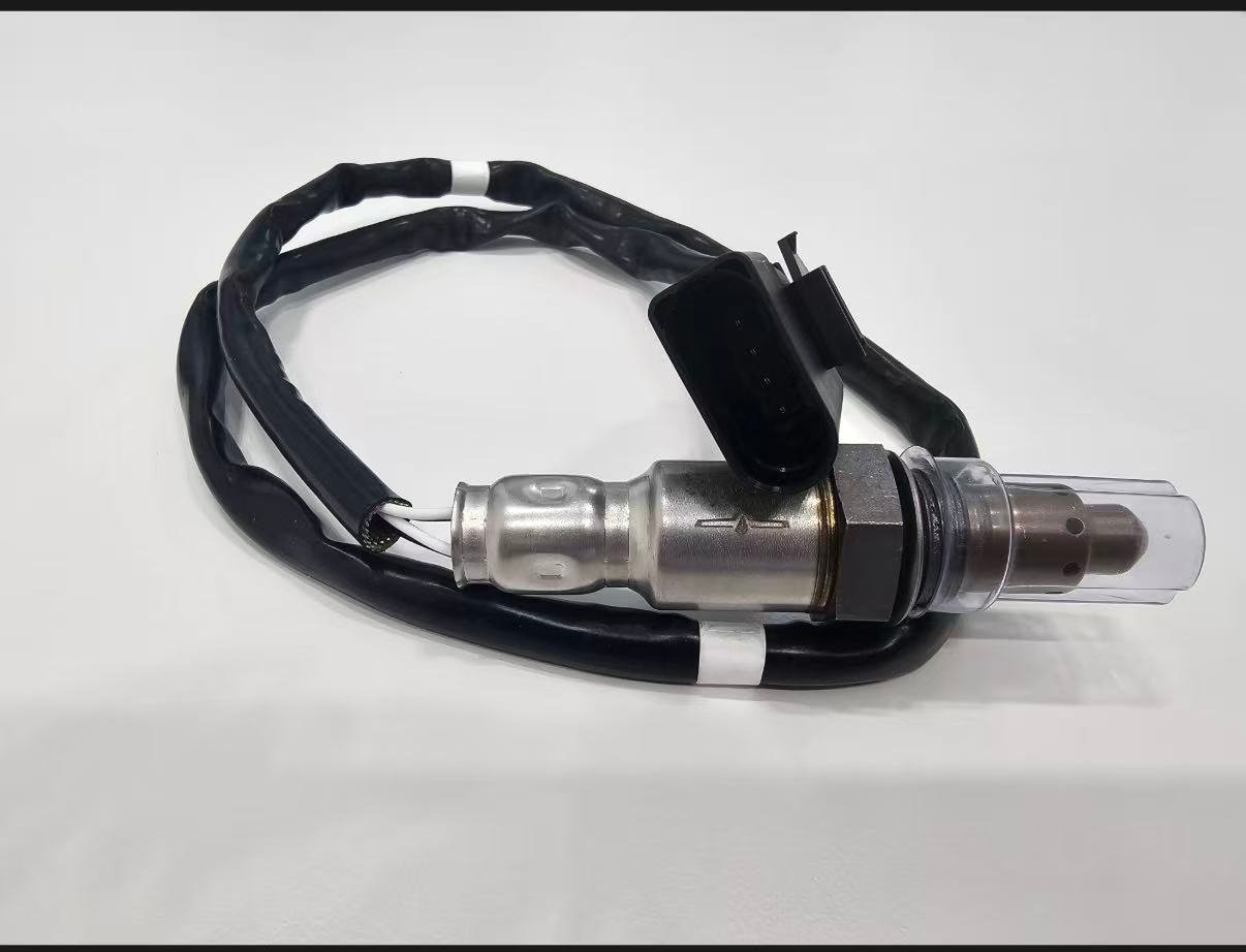
| Schnittstelle | Gewinde, Abschirmung, Steckercodierung, Stifte, Litzen und Klemmen | Stecker erzwungen, Kabel gedehnt oder Klemmen weggelassen |
| Diagnosegrundlage | Fehlgeschlagener Schaltkreis- oder Reaktionstest, nachdem konkurrierende Ursachen geprüft wurden | Symptomliste oder Codenummer als alleiniger Beweis |
Was jedes häufige Symptom Ihnen sagen kann und was nicht
Motorkontrollleuchte und gespeicherte Codes
Die Warnleuchte bestätigt, dass das Steuersystem einen überwachten Zustand erkannt hat; sie identifiziert nicht die physische Ursache. Notieren Sie jeden Code und seinen Status, da ein Gemisch- oder Fehlzündungscode die Interpretation eines Sauerstoffsensor-Codes ändern kann. Der Freeze Frame legt einen nützlichen Ausgangszustand fest, aber ein einzelner erfasster Frame kann das erste Ereignis in der Ursachenkette nicht enthalten.
Kraftstoffverbrauch und Bordcomputer-Schätzwerte
Eine kurzfristige Bordcomputer-Schätzung reagiert empfindlich auf Leerlaufzeiten, Verkehr, Temperatur, Kraftstoffmischung, Reifendruck und Fahrstil. Etablieren Sie eine reproduzierbare Basislinie anhand des tatsächlich nachgefüllten Kraftstoffs und der zurückgelegten Strecke bei vergleichbarem Betrieb. Wenn die Kraftstoffkorrektur abnormal ist, stellen Sie fest, ob der Sensor vorgespannt ist oder einen Motorzustand genau meldet. Der Austausch eines korrekt meldenden Sensors kann den durch ein Ansaugleck, ein Thermostatproblem, eine schleifende Bremse oder ein undichtes Einspritzventil verlorenen Verbrauch nicht wiederherstellen.
Leerlaufqualität, Zögern und schwache Beschleunigung
Diese Beschwerden können von Zündung, Kraftstoffzufuhr, Luftmessung, variabler Ventilsteuerung, Kompression, Abgasgegendruck oder Getriebeverhalten herrühren. Sauerstoffsensordaten können helfen, das Gemischverhalten zu erklären, sind aber selten der einzige nützliche Kanal. Korrelieren Sie das Ereignis mit Fehlzündungszählern, berechneter Last, Luftstrom, Drosselklappe, Kraftstoffdruck oder befohlenem Äquivalenzverhältnis, soweit vom Fahrzeug unterstützt.
Rauch-, Geruchs- und Ablagerungsnachweis
Schwarzer Rauch oder Kraftstoffgeruch erhöht die Dringlichkeit von Prüfungen auf fettes Gemisch und Fehlzündungen. Blauer oder ölbedingter Rauch und Kühlmittelverlust weisen auf andere Motorzustände hin, die sowohl Sensor als auch Katalysator verunreinigen können. Ein Foto der Ablagerungen ist für den Reparaturnachweis nützlich, aber kennzeichnen Sie die Chemie nicht allein anhand der Farbe und versuchen Sie nicht, das Sensorelement mit einem nicht zugelassenen Lösungsmittel zu reinigen.
Prüfungsausfall und unvollständige Bereitschaft
Eine Prüfung kann fehlschlagen, weil ein bestätigter Emissionsfehler vorliegt oder weil erforderliche Überwachungen nach dem Löschen von Fehlercodes oder einem Stromausfall nicht abgeschlossen wurden. Wiederholtes Löschen des Speichers kann ein gültiges Ergebnis verzögern und nützliche Diagnosehistorie verbergen. Beheben Sie die Ursache, erhalten Sie die gesetzlichen Emissionskontrollen und führen Sie die geltende Fahr- oder Überwachungsprozedur durch. Distanzstücke, Simulatoren, Deaktivierungen und Software-Monitor-Umgehungen sind keine Reparaturmethoden.
Mindestreparatur- und Garantieaufzeichnung
Ein aussagekräftiger Bericht ermöglicht es einem anderen Techniker, Händler oder Lieferanten, die Entscheidung nachzuvollziehen. Er trennt außerdem falsche Montage, Installationsschäden, ungeklärte Fahrzeugfehler und mögliche Produktabweichungen. Nicht verfügbare Informationen als KEINE DATEN VERFÜGBAR; ausweisen, ein fehlendes Ergebnis nicht als bestandenes Ergebnis darstellen.
- Fahrzeugidentität, Motor, Markt-/Emissionskonfiguration und Kilometerstand zum Zeitpunkt der Diagnose
- Exakte Sensorposition und verwendete Service-Informationsbasis zur Identifizierung
- Alle Codes, Status, Freeze-Frame, Bereitschaft und relevante Live-Datenaufzeichnungen
- Verkabelung, beheizter Heizstab, Abgasleck-, Kraftstoff-Trim- und Reaktionstestergebnisse
- Alte und neue Teilenummern, OE-Zuordnungsquelle, Verpackung und Chargen-/Datumsaufzeichnung
- Steckverbinder, Kontakte, Ablagerungen, Verlegung und Fotos des eingebauten Freiraums
- Reaktion nach der Reparatur und Überwachung des Ergebnisses unter dokumentierten Bedingungen
Bereiten Sie eine Montage- oder Beschaffungsanfrage vor
Senden Sie die OE-Nummer, Baujahr/Marke/Modell, Motor- oder Fahrgestelldaten, Markt- und Emissionspaket, genaue Bank-/Sensorposition, Stecker- und Altteilfotos, Menge sowie etwaige Verpackungs- oder Zulassungsanforderungen. Sunhyings prüft die gelieferten Daten auf Eignung und Beschaffungsmöglichkeit; die Passgenauigkeit wird erst bestätigt, wenn die Anwendungsnachweise übereinstimmen.
Häufig gestellte Fragen
Was ist das häufigste Anzeichen für einen defekten Sauerstoffsensor?
Eine Motorkontrollleuchte ist üblich, aber der Code und die Live-Daten müssen diagnostiziert werden, da Verkabelungs-, Gemisch- und Abgasfehler ähnliche Warnungen auslösen können.
Kann ein defekter O2-Sensor unruhigen Leerlauf verursachen?
Es kann zu einer falschen Kraftstoffkorrektur beitragen, aber Unterdrucklecks, Zündungsfehler, Einspritzdüsen und mechanische Probleme sind ebenfalls häufige Ursachen.
Bedeutet P0420, dass der Sauerstoffsensor defekt ist?
Nr. P0420 betrifft die Effizienz des Katalysatorsystems. Sensordaten sind Teil der Diagnose, aber der Code beweist nicht, dass der Sensor ausgefallen ist.
Kann ich mit einem Sauerstoffsensor-Fehlercode weiterfahren?
Das hängt von den Symptomen und dem Fehler ab. Eine blinkende Warnleuchte, starker Kraftstoffgeruch, schweres Fehlzünden oder großer Leistungsverlust erfordern sofortige professionelle Aufmerksamkeit.
Sollte ich alle Sauerstoffsensoren gleichzeitig ersetzen?
Nicht automatisch. Testen Sie den identifizierten Stromkreis und ersetzen Sie nur Teile, die durch die Diagnose und das Fahrzeugserviceverfahren gestützt werden.