








Technischer Leitfaden für Sauerstoffsensoren
Verstehen Sie, was die häufigsten Sauerstoffsensor-Fehlercodes P0130-P0167 identifizieren, warum P0420 anders ist und welche Stromkreis- und Systemprüfungen vor dem Austausch durchgeführt werden.

Kurze Antwort
Die Codes P0130-P0167 identifizieren im Allgemeinen einen Sauerstoffsensor-Stromkreis, Heizung, Aktivität oder Reaktionszustand für einen bestimmten Bank und Sensor. Sie beweisen nicht, dass das Messelement defekt ist. Diagnostizieren Sie Verkabelung, Steckverbinder, Stromversorgung und Masse, Abgaslecks, Gemischbedingungen und Live-Daten. P0420/P0430 betreffen die Effizienz des Katalysatorsystems und sollten nicht als automatische Codes für den Austausch des Sauerstoffsensors behandelt werden.
Code-Familien und die Frage, die jede aufwirft
| Beispielfamilie | Allgemeine Bedeutung | Erste Diagnosefrage |
|---|---|---|
| P0130 / P0150 | Fehler im Sensorstromkreis | Ist der Signalstromkreis intakt und ist der Motorzustand plausibel? |
| P0131-P0132 / P0151-P0152 | Niedriges oder hohes Signal | Handelt es sich um eine elektrische Begrenzung, eine tatsächliche Gemischbedingung oder eine Verunreinigung? |
| P0133 / P0153 | Langsame Reaktion | Sind die Betriebsbedingungen korrekt und verlangsamen Lecks oder Kraftstofffehler die beobachtete Übergangszeit? |
| P0134 / P0154 | Keine Aktivität erkannt | Ist der Sensor warm, versorgt und angeschlossen, und erreicht das Signal das Steuergerät? |
| P0135 / P0141 / P0155 / P0161 | Heizkreisstörung | Liegen Heizleistung, Masse, Sicherung, Steuerung und Widerstand innerhalb der Spezifikation? |
| P0420 / P0430 | Katalysatorwirkungsgrad unterhalb des Schwellenwerts | Sind Motor-, Abgas-, Sensordaten und Katalysatorzustand alle gültig? |
Die genaue Definition und die Aktivierungskriterien variieren je nach Hersteller. Lesen Sie immer die vollständige Beschreibung, die Freeze-Frame-Daten und das Serviceverfahren für das Fahrzeug.
Bank und Sensor entschlüsseln, bevor ein Teil berührt wird
Bank 1 enthält Zylinder 1; Bank 2 ist die gegenüberliegende Bank, falls vorhanden. Sensor 1 befindet sich üblicherweise vor dem Katalysator und Sensor 2 nach dem Katalysator. Verwenden Sie keine universelle Fahrerseiten-Regel. Eine korrekte Diagnose am falschen physischen Sensor ist immer noch eine falsche Reparatur.
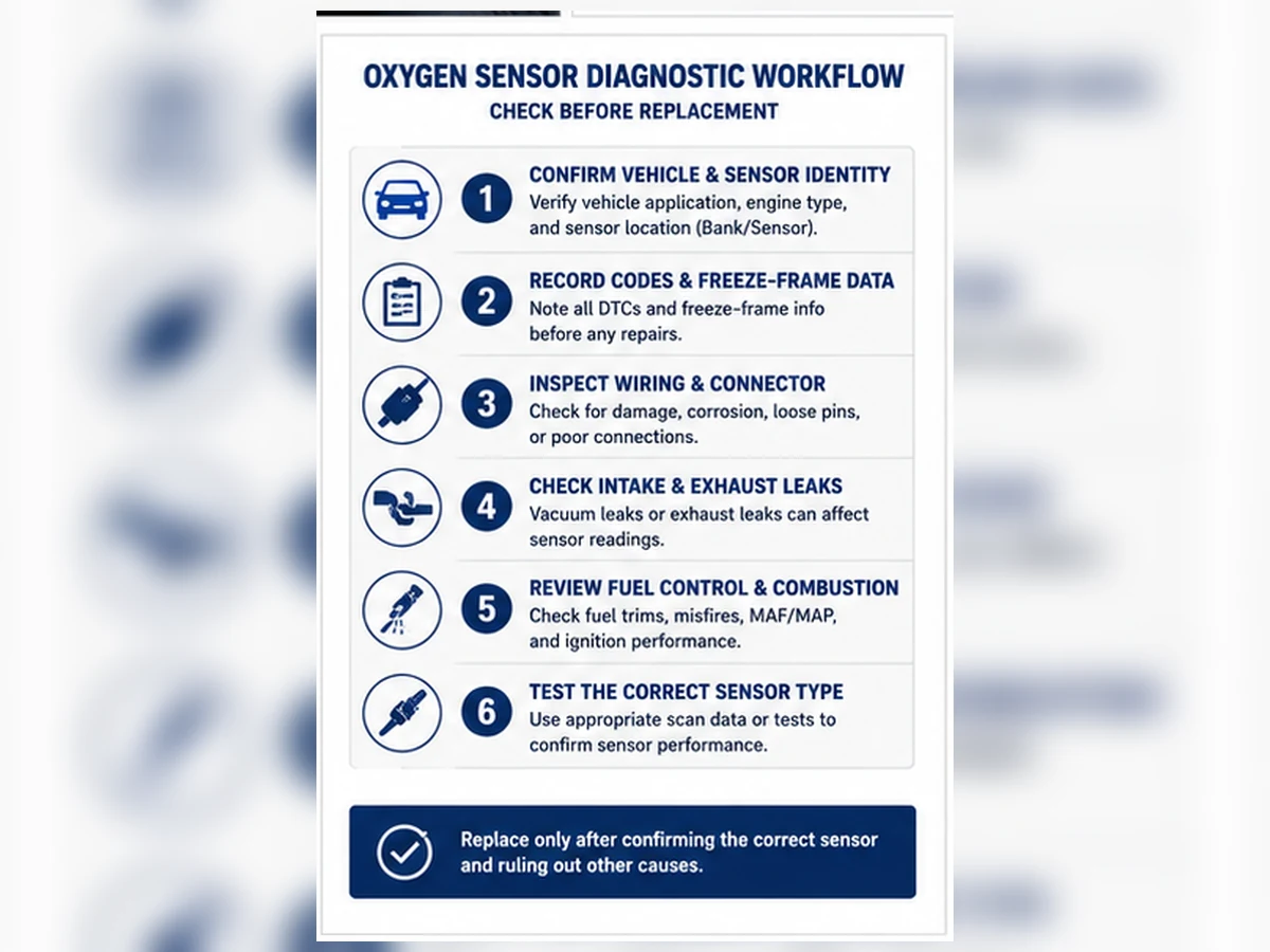
Eine sechsstufige Diagnosereihenfolge
- Zeichnen Sie alle aktuellen, anstehenden und permanenten Codes sowie Freeze-Frame-Daten auf.
- Bestätigen Sie die genaue Bank, den Sensor und die Technologie.
- Überprüfen Sie die Kabelbaumführung, den Zustand des Steckers und Abgaslecks.
- Testen Sie die Heizungsstromversorgung, Masse und Steuerung, wenn der Code die Heizung betrifft.
- Überprüfen Sie die Kraftstofftrimms und die Sensorspannung, den Strom oder Lambda wie angegeben.
- Reparieren Sie die Ursache und überprüfen Sie den Monitor ohne Bypass-Vorrichtungen.
Warum P0420 und P0430 besondere Aufmerksamkeit erfordern
Diese Codes bewerten das Verhalten des Katalysatorsystems unter Verwendung mehrerer Bedingungen und Sensorsignale. Abgaslecks, Fehlzündungen, Kraftstoffregelungsprobleme, Sensorabweichungen und Katalysatorverschlechterung können das Ergebnis beeinflussen. Der Austausch eines nachgeschalteten Sensors ohne Überprüfung seines Signals und des restlichen Systems kann die Reparaturmöglichkeit verschwenden.
Maßnahmen, die die Diagnose nicht abschließen
Das Löschen des Codes, das Abklemmen der Batterie, das Anbringen eines Abstandshalters oder Simulators oder das wiederholte Austauschen von Sensoren ermittelt nicht die Ursache. Emissionskontrollen müssen gemäß den geltenden Gesetzen repariert werden. Nutzen Sie Informationen zu permanenten Codes und Bereitschaft, um den legalen Reparaturprozess zu überprüfen.
Jeden DTC als System, Position und Fehlermodus lesen
Eine vollständige Codebeschreibung kombiniert das überwachte System, die Bank-/Sensorposition und die Fehlerart wie z. B. niedriger Stromkreis, hoher Stromkreis, keine Aktivität, langsame Reaktion oder Heizungsfehler. Der Code gibt an, welcher Testpfad geöffnet werden muss. Er identifiziert nicht den austauschbaren Sensor als Fehlerpunkt und liefert keine Teilenummer.
| Codeelement | Beantwortete Frage | Frage nicht beantwortet |
|---|---|---|
| Bank 1 / Bank 2 | Welche Motorseite wird überwacht? | Universelle physische Seite |
| Sensor 1 / Sensor 2 | Gemeinsame Position vor/nach Katalysator | Exakter Stecker ohne Schaltplan |
| Niedrige/hohe/keine Aktivität | Erkannter Signalzustand | Sensor versus Verkabelung versus tatsächliches Gemisch |
| Heizkreis | Überwachungskriterien für fehlgeschlagenen Heizpfad | Element vs. Sicherung/Strom/Masse/Steuerung |
Diagnostische Bedeutung gängiger Code-Familien
Stromkreisstörung, Low- und High-Codes
P0130/P0150 und verwandte Low/High-Codes erfordern Stromkreis- und Plausibilitätsprüfungen. Prüfen Sie Signal- und Referenzstromkreise, Anschlusszustand und Abgas-/Gemischhinweise. Ein niedriger Wert kann einen echten Magerzustand widerspiegeln; ein hoher Wert kann einen Fettbetrieb anzeigen. Elektrische Grenzwerte und Service-Spezifikationen bestimmen die Unterscheidung.
Langsame Reaktion und keine Aktivität
P0133/P0153 und No-Activity-Familien erfordern gültige Betriebstemperatur und Enable-Bedingungen. Prüfen Sie Heizungsbetrieb, Lecks, tatsächliche Gemischreaktion und Scan-Tool-Datenrate. Ein flacher, nicht unterstützter PID ist kein Beweis für einen defekten Sensor.
Heizungscodes
P0135, P0141, P0155, P0161 und verwandte Codes öffnen einen Heizungsstromkreis. Testen Sie geschützte Versorgung, Sicherung, Masse/Steuerung, Stecker, Kabelbaum und Element gemäß Schaltplan. Der Widerstand allein beweist nicht, dass unter Last Strom geliefert wird.
Freeze-Frame- und Bereitschaftsnachweise erhalten
Aktuelle, anstehende und permanente Codes vor dem Löschen aufzeichnen. Freeze Frame zeigt den Motorzustand, als der Monitor einen Fehler erkannte, und kann Kaltstart, Leerlauf, Last- oder Drehzahlkontext offenbaren. Der Bereitschaftsstatus zeigt an, welche Monitore abgeschlossen sind. Das Löschen von Codes entfernt nützlichen Kontext und setzt Monitore zurück, daher sollte es nicht der erste Diagnoseschritt sein.
| Aufzeichnung | Warum aufbewahren | Häufiger Fehler |
|---|---|---|
| Alle Codes | Zeigt gemeinsame Leistungs-, Gemisch- oder Fehlzündungsmuster | Konzentration nur auf einen O2-Code |
| Standbild | Definiert Erkennungsbedingungen | Löschen vor dem Speichern |
| Bereitschaft | Zeigt Monitordurchführung an | Annahme, dass kein Licht bedeutet, dass alle Tests bestanden wurden |
| Permanenter DTC | Erfordert monitorbestätigte Reparatur | Versuch, es manuell zu löschen |
Bestätigen Sie den durch den Code bezeichneten physischen Stromkreis
Bank 1 enthält Zylinder 1. Sensor 1 befindet sich üblicherweise vor dem Katalysator und Sensor 2 danach. Verwenden Sie keine universelle Fahrerseiten-Regel. Ordnen Sie den Code dem Abgasdiagramm und der Steckerverlegung zu. Das Testen des falschen Sensors kann technisch korrekte Messungen für den falschen Stromkreis liefern.
Sechs Prüfungen vor einer Teileentscheidung
- Code-Definition und Aktivierungskriterien für das genaue Fahrzeug bestätigen.
- Bank, Position und Sensortechnologie identifizieren.
- Steckverbinder, Anschlüsse, Wärmeführung und Abgaslecks prüfen.
- Heizung und Signalkreise mit dem korrekten Schaltplan testen.
- Kraftstofftrimms, Sollzustand und Sensorreaktion vergleichen.
- Die Ursache beheben und den Monitor ordnungsgemäß überprüfen.
| Fehlermodus | Erste physische Prüfung | Erforderliche Systemprüfung |
|---|---|---|
| Heizung | Kabelbaum, Steckverbinder und geschützte Versorgung | Steuerung/Erdung unter festgelegten Bedingungen |
| Nieder-/Hochsignal | Signal-/Referenzintegrität | Tatsächliches Fett-/Magerverhältnis und Lecks |
| Keine Aktivität | Anschluss und Heizbetrieb | Unterstützte PID und Betriebstemperatur |
| Langsame Reaktion | Kontaminations- und Abgasintegrität | Kontrollierte technologiespezifische Reaktion |
P0420/P0430 sind ein separater Katalysatorsystempfad
Diese Codes bewerten die Katalysatorsystemeffizienz anhand des Verhaltens von Vor- und Nachkat-Sonden unter definierten Bedingungen. Sie können durch Katalysatorverschlechterung, Abgaslecks, Fehlzündungen, Kraftstoffregelungsprobleme und Sensorabweichungen beeinflusst werden. Sie gehören nicht zur Sensorstromkreisfamilie P0130-P0167 und sollten ohne Validierung nicht in eine Nachkatsonden-Bestellung umgewandelt werden.
Wählen Sie Werkzeuge anhand der Frage
Scan-Tool
Verwenden Sie es für Codes, Freeze Frame, Bereitschaft, Trims und unterstützte Sensordaten. Bestätigen Sie Einheiten und Abtastrate. Ein Diagramm erfordert dennoch bekannte Betriebsbedingungen.
Multimeter und Oszilloskop
Verwenden Sie ein Messgerät für spezifizierte Spannungs-, Masse-, Durchgangs- oder Widerstandsprüfungen und ein Oszilloskop, wo Wellenformdetails erforderlich sind. Vermeiden Sie Prüfmethoden, die Kontakte aufweiten oder Breitbandschaltungen beschädigen.
Dichtheits- und mechanische Prüfungen
Ansaug- oder Abgaslecks, Kraftstoffzufuhr, Zündung und Motorzustand können das gemeldete Abgasverhalten verursachen. Verwenden Sie sichere, anwendungsgerechte Methoden und beheben Sie diese Bedingungen, bevor Sie den Melder verurteilen.
Komplexes Szenario: Ein Heizungscode überlebt den Sensorwechsel
Komplexes Diagnoseszenario: Ein neuer Sensor wurde für P0141 eingebaut, aber der Fehlercode kehrt zurück. Der korrekte Schaltplan und der Belastungstest zeigen eine fehlende Versorgung am Stecker aufgrund von hitzegeschädigter Verkabelung. Die Reparatur und Neuverlegung des Kabelbaums stellt den Stromkreis wieder her. Dieses zusammengesetzte Beispiel ist kein Fall von Sunhyings oder ein Nachweis für ein bestimmtes Fahrzeug.
Überprüfen Sie den ursprünglichen Monitor, nicht nur die Warnleuchte
Bestätigen Sie nach der Reparatur die physische Verlegung, die Stromkreisfunktion und plausible Live-Daten. Führen Sie die vom Hersteller geforderten Überwachungsbedingungen sicher und legal durch. Ein permanenter Fehlercode kann bestehen bleiben, bis die Überwachung bestanden ist. Batterietrennung, wiederholtes Löschen, Abstandshalter, Simulatoren oder Software-Manipulation beweisen keine Reparatur und können die Emissionskonformität beeinträchtigen.
Erstellen Sie einen Reparaturbericht, der einer Rückkehr standhält
Speichern Sie den ursprünglichen Fehlercode-Status, das Freeze-Frame, die Stromkreiswerte, Leck- oder Gemischbefunde, die physische Position, das reparierte Bauteil und die Daten nach der Reparatur. Fügen Sie Fotos von Steckern und Verlegung hinzu, wenn Hitze oder intermittierende Bewegung beteiligt waren. Wenn der Fehlercode zurückkehrt, verhindert dieser Datensatz, dass der Diagnoseprozess mit einem weiteren nicht unterstützten Sensorwechsel neu gestartet wird.
Fügen Sie bei einer Teilerückgabe die OE-/Anwendungsbasis, das gelieferte Teil und die Charge, die Einbauposition und die fahrzeugseitigen Stromkreisergebnisse hinzu. Ein zurückgesandter Sensor kann nicht fair beurteilt werden, wenn der Verkäufer nur die Fehlernummer erhält. Trennen Sie Katalogfehler, Einbauschaden, ungelöste Ursache, Fahrzeugverkabelung und Produktabweichung.
Wenn mehrere Lambdasonden-Fehlercodes gleichzeitig auftreten
Prüfen Sie gemeinsame Versorgungen, Masse, Kabelbaumschäden oder systemweite fett/mager-Bedingungen, bevor Sie jeden Fehlercode als unabhängigen defekten Sensor behandeln. Mehrere Heizungsfehlercodes können auf eine geschützte Versorgung hinweisen; mehrere gemischbezogene Fehlercodes können auf Luft-, Kraftstoff- oder Abgasursachen hinweisen. Der Schaltplan und der vollständige Fehlercodesatz bestimmen, ob die Fehler einen gemeinsamen Pfad haben.
Ein Fehlercode, der von aktuell zu historisch wechselt oder nach dem Löschen verschwindet, hat nicht unbedingt seine Überwachung bestanden. Dokumentieren Sie, wie sich der Status durch die angegebenen Fahrbedingungen ändert und ob die Bereitschaft abgeschlossen wird. Intermittierende Hitze- oder Vibrationsfehler können eine Beobachtung während des Aufwärmens und der Kabelbaumbewegung mit sicheren Methoden erfordern. Die Verifikation muss die Frage der Überwachung reproduzieren, nicht nur ein sauberes Armaturenbrett erzeugen.
So lesen Sie einen Sauerstoffsensor-DTC, ohne ihn in eine Teilebestellung zu verwandeln
Ein OBD-II-Code benennt einen überwachten Stromkreis, ein Signalverhalten oder ein Systemergebnis. Er enthält nicht die Sensortechnologie, den Stecker, die Kabellänge, das Gewinde, die Kalibrierung oder die bestätigte Ersatzteilnummer. Beginnen Sie damit, die vollständige Fehlercodebeschreibung, den Status und die Freeze-Frame-Bedingungen zu notieren. Ordnen Sie dann Bank- und Sensoridentität anhand von Serviceinformationen zu, bevor Sie einen Stecker berühren.
Der bekannte Bereich P0130-P0167 umfasst Signalstromkreis-, Nieder-/Hochspannungs-, Langsamreaktions-, Inaktivitäts- und Heizkreisprobleme über zwei Bänke und zwei Sensorpositionen. Herstellerspezifische Codes und Breitband-/Luft-Kraftstoff-Strategien können unterschiedliche Beschreibungen und Tests verwenden. Die Codefamilie ist ein Routing-Index, keine universelle Testspezifikation.
| Codefamilie | Überwachungsproblem | Prüfungen vor dem Austausch | Häufige Fehlschlussfolgerung |
|---|---|---|---|
| P0130 / P0150 | Störung des Sensor-1-Stromkreises | Steckverbinder, Signal-/Referenzstromkreise, Abgaslecks, Gemischzustand und Reaktion | “Stromkreis” bedeutet immer, dass das Messelement offen ist |
| P0131 / P0151 | Sensor 1 niedrige Anzeige | Tatsächliches Magerverhältnis, Signalkurzschluss, Referenzintegrität und Leck vor dem Sensor | Niederspannung weist immer auf einen mager laufenden Motor oder defekten Sensor hin |
| P0132 / P0152 | Sensor 1 hohe Anzeige | Tatsächlicher Fettbetrieb, Signalkurzschluss, Kraftstoffdruck, Einspritzer- und Spülsystem-Hinweise | Hochspannung bedeutet immer, dass der Sensor feststeckt |
| P0133 / P0153 | Langsame Reaktion | Betriebstemperatur, Abgaslecks, Kontamination, Prüfbedingungen und Kreislauf | Ein Langsamscan-Diagramm belegt Alterung |
| P0134 / P0154 | Keine erkannte Aktivität | Bedingungen aktivieren, Heizbetrieb, Signal-/Referenzkreise und Datenunterstützung | Ein konstanter Wert kommt immer vom Sensor |
| P0135 / P0155 | Heizkreis Sensor 1 | Sicherung, belastete Versorgung, Steuerung/Masse, Stecker und spezifizierter Widerstand/Strom | Jeder Heizcode erfordert einen Sensor |
| P0136 / P0156 | Fehlfunktion des Sensor-2-Stromkreises | Freiliegender hinterer Kabelbaum, Steckverbinder, Stromkreisintegrität und Abgaszustand | Ein hinterer Stromkreiscode ist ein Katalysatorurteil |
| P0137 / P0157 | Niedrige Anzeige von Sensor 2 | Signalkreis, Lecks, tatsächliches Gemisch und Überwachungsbedingungen | Ersetzen Sie den hinteren Sensor, ohne die Abgasleckage zu überprüfen |
| P0138 / P0158 | Sensor 2 hohe Anzeige | Signal kurz, tatsächlich fettes Gemisch, Verschmutzung und Stromkreis | Ein konstanter fetter Wert weist auf Katalysatorausfall hin |
| P0139 / P0159 | Sensor 2 langsame Reaktion | Genaue Überwachungsprozedur, Temperatur, Lecks und Sensor-/Stromkreisreaktion | Vergleichen Sie den hinteren Sensor direkt mit dem vorderen Schaltverhalten zu jeder Zeit |
| P0140 / P0160 | Sensor 2 keine Aktivität | Bedingungen aktivieren, Signalweg, Steckverbinder und Heizungsbetrieb | Kein sichtbares Schalten ist bei einem hinteren Sensor immer abnormal |
| P0141 / P0161 | Heizkreis Sensor 2 | Geschützte Stromversorgung, Steuerung/Masse, Steckverbinder und Kabelbaum in der Nähe des Auspuffs | Ersetzen und später den Stromkreis testen |
Aktuelle, anstehende und permanente Codes beantworten unterschiedliche Fragen
Ein aktueller oder bestätigter Code zeigt an, dass der Monitor seine Bestätigungslogik erfüllt hat. Ein anstehender Code kann einen frühen Fehler vor der Bestätigung speichern. Ein permanenter Code wird gemäß der regulierten OBD-Logik gespeichert, bis das System den erforderlichen erfolgreichen Betrieb beobachtet; er ist nicht unbedingt ein Beweis dafür, dass die Reparatur unmittelbar nach dem Teileaustausch fehlgeschlagen ist. Definitionen und Löschverhalten variieren je nach Regulierung und Fahrzeugstrategie, daher verwenden Sie das Scan-Tool und die Serviceinformationen korrekt.
| Aufzeichnung | Was es beiträgt | Was es nicht nachweisen kann |
|---|---|---|
| Code-Status | Ob der Fehler ansteht, bestätigt oder als dauerhaft gespeichert ist | Welche physische Komponente den Zustand verursacht hat |
| Standbild | Last, Drehzahl, Temperatur und andere erfasste Bedingungen zum Zeitpunkt des Fehlers | Jede Änderung, die vor oder nach der Erfassung aufgetreten ist |
| Bereitschaft | Ob relevante Überwachungen seit dem Reset oder der Reparatur abgeschlossen wurden | Dass ein unvollständiges System durchgelaufen ist |
| Modus 6 oder Monitordaten | Vom Hersteller unterstützte Monitorergebnisse und Grenzwerte, sofern verfügbar | Eine universelle Diagnose ohne korrekte Testidentifikation und Skalierung |
| Live-Daten | Verhalten während kontrollierter Betriebszustände | Ursache ohne Kontext von Stromkreis, Motor und Abgas |
Entscheidungspfad für Heizungscodes
Die Heizung bringt das Sensorelement auf Betriebstemperatur und hilft, diese bei niedrigem Abgasdurchsatz aufrechtzuerhalten. Je nach Ausführung kann das Steuergerät Widerstand, Strom, Spannung oder Zeit bis zur Aktivität überwachen. Beginnen Sie mit dem korrekten Schaltplan und der Pin-Identifikation. Überprüfen Sie die Sicherung oder die gemeinsame Versorgung, aber hören Sie nicht bei der Durchgangsprüfung auf. Eine korrodierte Verbindung kann einen Niedrigstrom-Messwert bestehen und unter Heizlast ausfallen.
- Bestätigen Sie die Codenamen für die genaue Bank, den Sensor und den Heizkreis.
- Überprüfen Sie den Kabelbaum vom Stecker bis zum geschützten Kabelkanal, insbesondere in der Nähe von Abschirmungen und beweglichen Komponenten.
- Überprüfen Sie die Versorgung und Steuerung oder Masse unter den angegebenen Bedingungen und bei Last.
- Messen Sie den Widerstand oder Strom auf der Sensorseite nur bei der angegebenen Temperatur und den Grenzwerten.
- Überprüfen Sie gemeinsame Stromkreise und zugehörige Fehlercodes, bevor Sie ein isoliertes Teil ersetzen.
- Bestätigen Sie nach der Reparatur den Heizbetrieb und überwachen Sie die Fertigstellung, anstatt nur den Speicher zu löschen.
Entscheidungspfad für Signalcodes
Bei Codes für niedrige, hohe, langsame oder keine Aktivität stellen Sie fest, ob das Steuergerät einen tatsächlichen Abgaszustand sieht. Prüfen Sie auf Lecks vor dem Sensor und vergleichen Sie Kraftstofftrim, Luftmassenstrom, Kühlmitteltemperatur, Kraftstoffdruck und Fehlzündungsnachweise. Weisen Sie Signal- und Referenzintegrität nach. Führen Sie dann einen technologisch korrekten Fett-/Mager- oder Reaktionstest unter den erforderlichen Temperatur- und Betriebsbedingungen durch.
Führen Sie keine Rückkontaktierung oder Spannungsmessung durch, es sei denn, das Serviceverfahren erlaubt dies. Breitband-Steuerkreise können durch Schmalband-Testgewohnheiten beschädigt oder falsch interpretiert werden. Ein grafisches Messgerät oder Diagnosetool ist nur nützlich, wenn dessen Datenpunkt, Skala und Abtastrate verstanden werden.
P0420 und P0430 sind Katalysatorsystem-Wirkungsgradecodes
P0420 und P0430 zeigen an, dass die Katalysatorüberwachung die Effizienz unterhalb des kalibrierten Schwellenwerts für die genannte Bank bewertet hat. Die Überwachung verwendet Sauerstoffsensorinformationen, aber der Code sagt nicht “Ersetzen Sie den nachgeschalteten Sauerstoffsensor”. Fehlzündungen, Gemischregelung, Öl- oder Kühlmittelkontamination, Abgasleckage, falsche Sensoren, Kalibrierungsprobleme und der Katalysatorzustand können alle eine Rolle spielen. Diagnostizieren Sie zuerst verwandte Fehler und befolgen Sie das Herstellerverfahren zur Katalysatorüberwachung.
| Nachweis | Warum es wichtig ist | Grenze |
|---|---|---|
| Verwandte Fehlzündungs- oder Kraftstoffregelungsfehlercodes | Sie können die Katalysatorleistung beeinträchtigen oder verzerren | Ihre Reparatur beweist nicht automatisch die Katalysatorgesundheit |
| Abgasleckprüfung | Externer Sauerstoff kann das Sensorverhalten verändern | Eine Sichtprüfung kann ein Leck übersehen, das sich bei Hitze öffnet |
| Korrekte Sensoridentität | Falsche Technologie oder Position kann die Überwachung ungültig machen | Ein passender Stecker ist kein Kalibrierungsnachweis |
| Vor-/Nachdaten | Ermöglicht Monitoranalyse unter gültigen Bedingungen | Ein einzelner Standbild-Screenshot ist kein vollständiger Katalysatortest |
| Öl-/Kühlmittelverbrauchsnachweis | Verunreinigungen können Sensor und Katalysator beeinträchtigen | Die Ablagerungsfarbe allein ist keine Laboranalyse |
Zusammengesetzter Fall: zwei Heizungscodes und ein gemeinsamer Versorgungsfehler
Komplexes technisches Szenario: Zwei Sensoren an verschiedenen Banken setzen Heizungscodes nach Unterbodenarbeiten. Der Austausch eines Sensors ändert keinen der Codes. Der Schaltplan zeigt eine geschützte Versorgung, die von beiden Heizungen gemeinsam genutzt wird. Ein belasteter Spannungstest findet einen hochohmigen Anschluss an einer gestörten Verbindungsstelle. Die Reparatur stellt den Strom für beide Kreisläufe wieder her und die Monitore werden abgeschlossen.
Der entscheidende Hinweis ist das typische Fehlermuster. Zwei Teile können ausfallen, aber ein gemeinsamer Stromkreis sollte vor der Bestellung zweier unabhängiger Komponenten untersucht werden. Dies ist ein zusammengesetztes Diagnosebeispiel, kein Kundenfall von Sunhyings.
Zusammengesetzter Fall: Eine hintere Sensoranforderung wurde durch vorgelagerte Beweise gestoppt
Komplexes technisches Szenario: Ein Fahrzeug zeigt P0420 ohne Sauerstoffsensor-Stromkreisfehlercode. Die vorgeschlagene Reparatur ist ein nachgeschalteter Sensor, weil sein Graph sich bewegt. Die Überprüfung ergibt eine intermittierende Fehlzündungshistorie und übermäßige Kraftstoffkorrektur auf der überwachten Bank. Das Team behebt den Motorfehler, überprüft die Abgasdichtung und wiederholt den Katalysatormonitor, bevor eine Entscheidung über Katalysator oder hinteren Sensor getroffen wird.
Ein sich bewegendes hinteres Signal ist für sich genommen kein Beweis für einen defekten hinteren Sensor, und ein stabiles hinteres Signal ist kein universeller Beweis für einen guten Katalysator. Die Aktivierungskriterien des Monitors und das Fahrzeugverfahren steuern die Interpretation. Dieses Szenario ist zusammengesetzt und enthält keine behauptete Reparaturrate oder Kundenidentität.
Erstellen Sie einen DTC-Testbericht, der die Übergabe übersteht
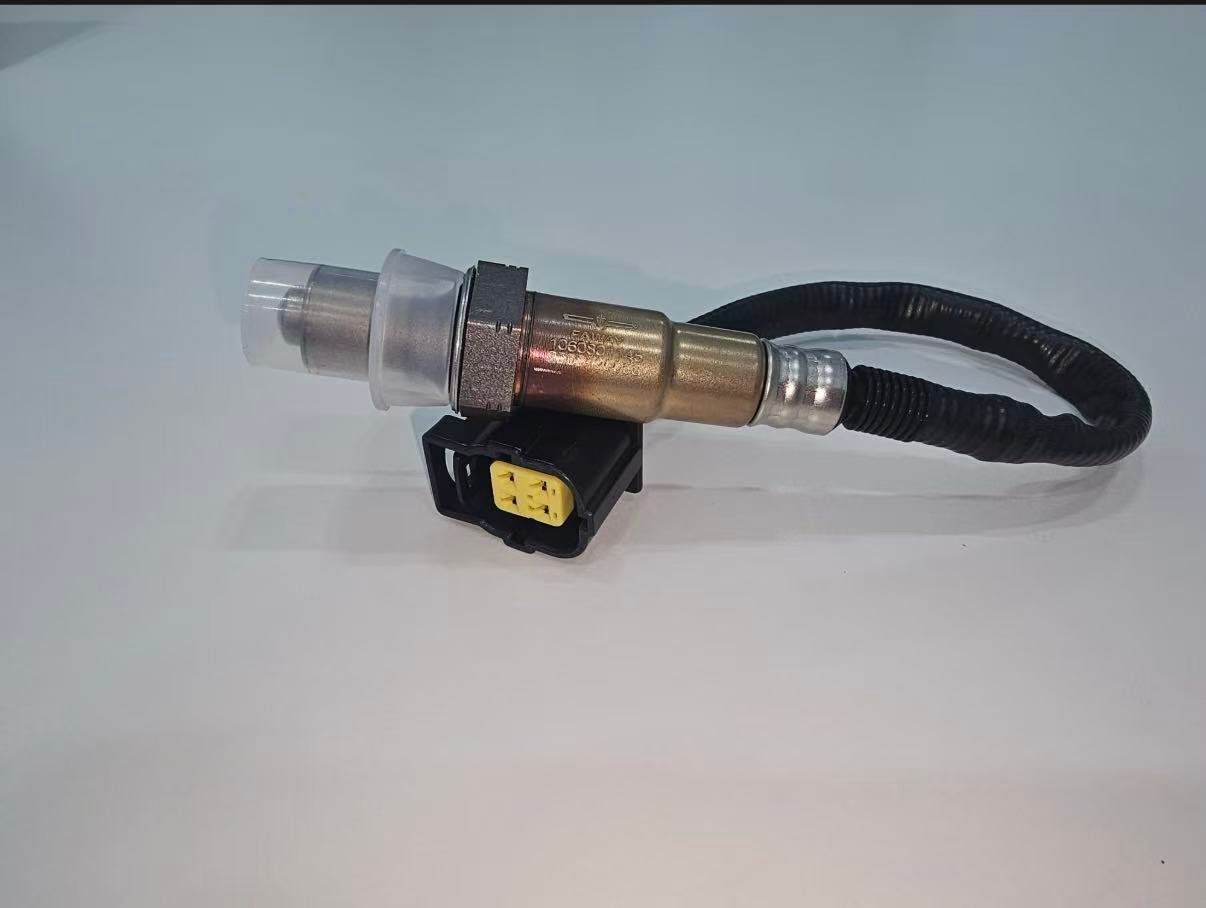
Eine Fehlercode-Diagnose wechselt oft zwischen Fahrer, Teiletheke, Werkstatt und Lieferanten. Dabei kann Kontext verloren gehen. Verwenden Sie einen kompakten Datensatz, der den Code mit dem physischen Stromkreis und den Bedingungen, unter denen er aufgetreten ist, verknüpft. Screenshots ohne Fahrzeugidentität oder Datenpunktbezeichnungen sind schwache Beweise; Werte ohne Einheiten oder Betriebsbedingungen können schlimmer sein als gar keine Daten.
| Feld aufzeichnen | Mindestinhalt | Grund |
|---|---|---|
| Fahrzeugidentität | VIN/YMME, Motor und Markt/Emissionspaket | Bestimmt Verkabelung, Monitorlogik und Passform |
| Code-Identität | Nummer, vollständige Beschreibung, Status und Modul | Verhindert, dass die Kurzschreibweise den Testpfad ändert |
| Fehlerbedingungen | Standbild, Temperatur, Last, Drehzahl und Kraftstoffzustand, sofern verfügbar | Unterstützt Reproduktion unter gültigen Bedingungen |
| Physische Identität | Bank/Sensor dem Stecker und der Abgasposition zugeordnet | Verhindert das Testen oder Austauschen des falschen Sensors |
| Schaltungsergebnisse | Stift, Methode, Last, Messwert, Einheit und Spezifikationsquelle | Macht elektrische Nachweise überprüfbar |
| Systemkontext | Nachweise zu Lecks, Trimmung, Fehlzündungen, Kraftstoff, Luftstrom und zugehörigen Codes | Trennt genaue Berichterstattung von Sensorverzerrung |
| Antwortresultat | Technologie, Betriebszustand, Stimulus und beobachtetes Verhalten | Verhindert, dass eine Schmalbanderwartung auf Breitband angewendet wird |
Grenze zwischen Teilezähler und E-Commerce
Ein Katalog kann ein verifiziertes Fahrzeug und eine OE-Referenz in passende Teile übersetzen. Er kann das Fahrzeug nicht anhand von P0135, P0141 oder P0420 diagnostizieren. Der Produktinhalt sollte die für die Auswahl erforderlichen Nachweise erläutern und keine Formulierungen wie “dieser Code bedeutet, dass Sie diesen Sensor benötigen” verwenden. Für Retouren sollten die vom Käufer getroffene Auswahl, die verwendete Katalogversion und ob das gelieferte Teil mit dem bestellten Datensatz übereinstimmt, dokumentiert werden.
Wenn ein Sensor eingebaut wurde, sollte der Fall untersucht werden, anstatt die Reklamation automatisch abzulehnen oder zu akzeptieren. Bestätigen Sie die genaue Anwendung, Position, elektrische Kompatibilität, Kabelverlegung und Testergebnisse. Ein fehlerfreies Prüfergebnis auf dem Prüfstand beweist nicht von selbst, dass die Fahrzeugdiagnose falsch war; ebenso beweist ein wiederkehrender Code nicht, dass das Ersatzteil defekt ist.
Emissionskonformitätsgrenze nach einem DTC
Das rechtliche Reparaturziel ist die Wiederherstellung des vorgesehenen Sensorsystems, Kraftstoffregelungssystems und Katalysatorüberwachungssystems. Installieren Sie keinen O2-Simulator, keine Sensor-Entfernung, keinen Defouler oder Abstandshalter, um einen Monitor zu manipulieren, und deaktivieren Sie keine Codes in der Software. Diese Ansätze beheben keine Schaltungs-, Motor- oder Katalysatorfehler und können gegen Emissionsvorschriften verstoßen. “Off-Road-Einsatz” ist keine universelle Ausnahme. Befolgen Sie die EPA/CARB-Anforderungen in den Vereinigten Staaten und die zuständige Behörde in anderen Märkten.
Nach einer ordnungsgemäßen Reparatur kann ein permanenter Code oder eine unvollständige Bereitschaft bestehen bleiben, bis das Fahrzeug die erforderliche Monitorsequenz abgeschlossen hat. Das ist keine Erlaubnis, den Monitor zu umgehen. Verwenden Sie das Serviceverfahren, bestätigen Sie, dass die Aktivierungsbedingungen erfüllt werden können, und untersuchen Sie jeden zurückkehrenden oder aktuellen Fehler.
Werkzeuge nach der Frage auswählen, nicht nach dem, was am einfachsten anzuschließen ist
Ein Scan-Tool beantwortet, was das Steuergerät meldet. Ein Digitalmultimeter kann Spannung, Widerstand oder Durchgang prüfen, wenn es innerhalb der Schaltungsgrenzen verwendet wird. Ein grafisches Multimeter oder Oszilloskop kann Timing und intermittierendes Verhalten aufzeigen. Eine Rauchmaschine kann helfen, Ansaug- oder Abgaslecks zu lokalisieren, wenn sie sicher und gemäß dem Systemverfahren verwendet wird. Keines ist eine universelle Wahrheitsquelle: Jedes Werkzeug hat Grenzen bei Abtastrate, Belastung, Zugang und Interpretation.
| Frage | Nützliche Methode | Erforderlicher Kontext | Fehlanwendung vermeiden |
|---|---|---|---|
| Hat das Modul einen überwachten Fehler erkannt? | Vollständiger Code-/Status-/Bereitschaftsscan | Korrektes Modul und vollständige Beschreibung | Nur einen generischen Code auslesen und Verlauf löschen |
| Kann der Heizkreis Strom führen? | Spezifizierter Belastungsspannungs-/Stromtest | Schaltplan, Pinbelegung, Betriebszustand und sichere Last | Alleinige Verwendung von Durchgangsprüfung als Nachweis der Stromkreiskapazität |
| Ändert sich das gemeldete Gemisch? | Technisch korrekte Scandaten oder Wellenform | Warmzustand, bekannter Reiz und unterstützter Parameter | Erwartung, dass jeder Sensor 0-1 V schaltet |
| Ist der Fehler intermittierend? | Grafische Darstellung, Kabelbaumbewegung und Zustandsreproduktion | Geschützte Prüfung und zeitgestempelte Betriebsdaten | Isolierung durchdringen oder Anschlüsse kurzschließen ohne Reparatur |
| Könnte Außenluft das Signal beeinflussen? | Kalt-/Heißleckprüfung mit zugelassener Methode | Position, Temperatur und Belüftung des Auspuffs | Anlegen eines unsicheren Drucks oder Ignorieren eines Lecks, das heiße Flüssigkeit freisetzt |
| Ist der Sensor der richtige Ersatz? | Kontrollierter Katalog, OE/Anwendung und physischer Vergleich | Exaktes Fahrzeug, Position und Technologie | Behandlung der Codebeschreibung eines Werkzeugs als Teilesuche |
Notieren Sie die Spezifikationsquelle neben jedem Bestanden/Nicht bestanden-Wert. Ein gemessener Widerstand hat ohne Sensortemperatur, Messgerätekonfiguration und anwendbaren Grenzwert wenig diagnostischen Wert. Ebenso benötigt ein Wellenform-Screenshot eine Zeitbasis, Skalierung, Betriebszustand und Kanalidentität. Diese Disziplin verbessert E-E-A-T, da der Leser sehen kann, wie eine Schlussfolgerung eingegrenzt wurde, anstatt aufgefordert zu werden, einer Teileempfehlung zu vertrauen.
Endgültige Entscheidung: reparieren, ersetzen, überwachen oder Diagnose fortsetzen
Wählen Sie einen Ersatz nur dann, wenn der genaue Sensor identifiziert ist und Belege für einen sensorseitigen Fehler sprechen, den der Fahrzeugstromkreis, die Abgasanlage und der Motorkontext nicht erklären. Reparieren Sie Verkabelung, Steckverbinder, Lecks oder Motorfehler, wenn diese Tests fehlschlagen. Setzen Sie die Diagnose fort, wenn die Ergebnisse widersprüchlich sind oder die Bedingungen für die Servicefreigabe nicht erfüllt wurden. Dokumentieren Sie nach jeder Reparatur dieselbe Codefamilie, Daten und den Monitorstatus, damit der Vorher-Nachher-Vergleich die ursprüngliche Frage beantwortet.
Wenn die Beweise einen Austausch stützen, identifiziert der DTC dennoch nicht das verkaufbare Teil. Führen Sie eine separate Passungsprüfung durch, unter Verwendung der OE-Referenz, Fahrzeug und Motor, Markt- oder Emissionskonfiguration, genaue Bank und Position, Technologie, Stecker, Pinbelegung, Leitungslänge und Verlegeclips. Diese Trennung zwischen Diagnose und Passungsprüfung verhindert, dass eine korrekte Reparaturentscheidung zu einer Bestellung der falschen Position wird.
Bereiten Sie eine Montage- oder Beschaffungsanfrage vor
Senden Sie die OE-Nummer, Baujahr/Marke/Modell, Motor- oder Fahrgestelldaten, Markt- und Emissionspaket, genaue Bank-/Sensorposition, Stecker- und Altteilfotos, Menge sowie etwaige Verpackungs- oder Zulassungsanforderungen. Sunhyings prüft die gelieferten Daten auf Eignung und Beschaffungsmöglichkeit; die Passgenauigkeit wird erst bestätigt, wenn die Anwendungsnachweise übereinstimmen.
Häufig gestellte Fragen
Bedeutet P0135 immer, dass der Heizkreis des Sauerstoffsensors defekt ist?
Nein. Das Heizelement, die Sicherung, die Verkabelung, der Stecker, die Stromversorgung, die Erdung oder der Steuerkreis könnten die Ursache sein.
Bedeutet P0133, dass der Sensor ersetzt werden muss?
Zuerst Betriebsbedingungen, Dichtheit der Abgasführung, Gemischregelung und den vorgeschriebenen Ansprechtest bestätigen.
Ist P0420 ein O2-Sensor-Fehlercode?
Es handelt sich um einen Effizienzcode des Katalysatorsystems, der Daten des Sauerstoffsensors verwendet; er beweist nicht, dass ein Sauerstoffsensor ausgefallen ist.
Kann ich den Code löschen, um die Reparatur zu testen?
Erfassen Sie zuerst die Diagnosedaten. Befolgen Sie das Fahrzeugverfahren, da das Löschen von Codes Beweise löschen und die Bereitschaftsmonitore zurücksetzen kann.
Was bedeutet Bank 1 Sensor 2?
Dies bezieht sich in der Regel auf den Nach-Katalysator-Sensor an der Bank mit Zylinder 1, vorbehaltlich fahrzeugspezifischer Bestätigung.