Oxygen Sensor Technical Guide
Use OE number, vehicle and engine data, sensor position, technology, connector and cable details to choose the correct oxygen sensor.

Quick answer
Choose an oxygen sensor by verified identity, not appearance. Start with the OE number and complete vehicle data, then confirm engine, market or emissions package, Bank and Sensor position, sensor technology, connector keying, pin count, cable length, thread and direct-fit or universal construction. A matching plug or wire count alone does not prove fit or calibration.
Build the minimum fitment identity
| Required input | Why it changes the decision |
|---|---|
| OE/OEM number | Anchors the search to the original application; aftermarket cross-references are candidates that still require verification. |
| Year, make and model | Defines the vehicle range but may not separate engines or emissions packages. |
| Engine / VIN or engine code | Distinguishes exhaust layout, calibration and connector variations. |
| Market and emissions package | Federal, California and other regional configurations may use different parts. |
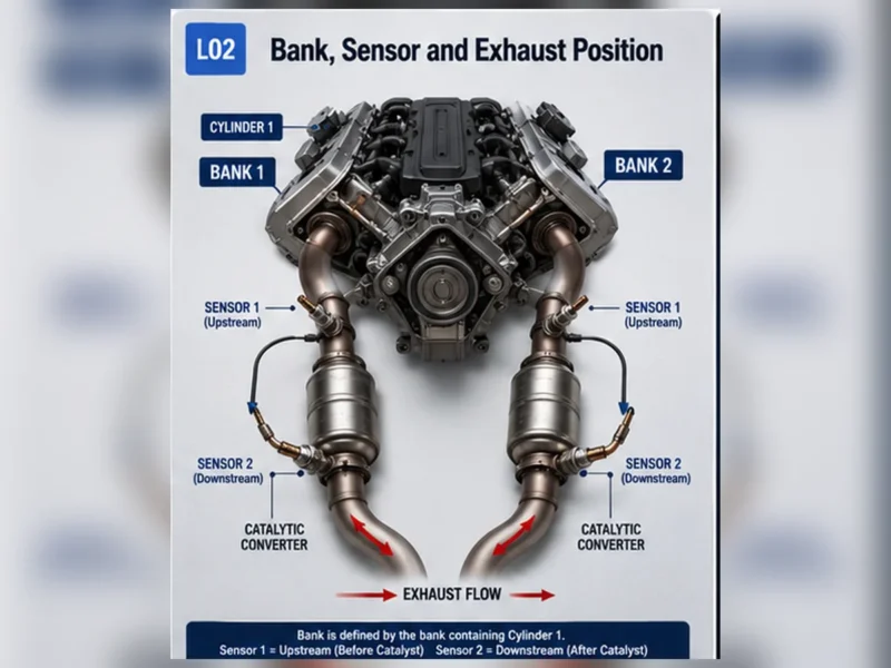
| Bank and Sensor position | Prevents ordering the correct family for the wrong exhaust position. |
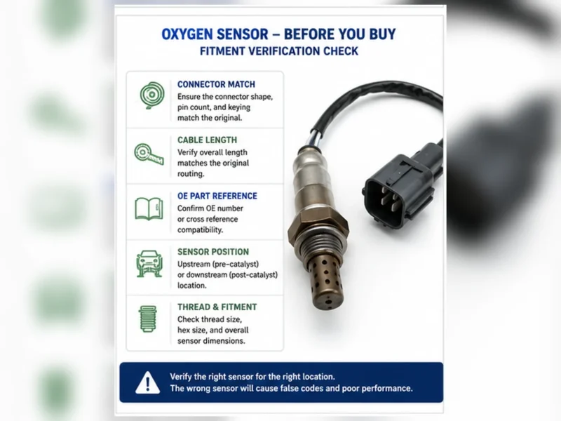
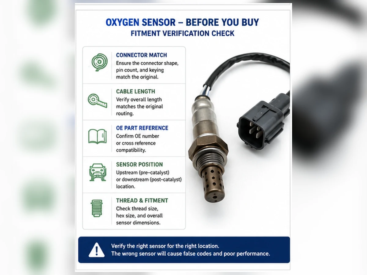
| Connector and cable | Keying, pin count, lead length and clip positions affect installation. |
| Sensor technology | Narrowband, wideband/A/F and titania designs are not selected by appearance alone. |
OE number versus aftermarket cross-reference
An OE number is a strong starting identifier, but supersessions and market-specific variants can exist. An aftermarket cross-reference is a catalog mapping, not automatic proof that every specification and position is identical. Verify the current catalog record against the vehicle and the removed part.
Confirm Bank and Sensor position
Bank 1 contains cylinder 1. Sensor 1 is generally upstream and Sensor 2 downstream for that bank. Do not assume Bank 1 is always on the same physical side. Use service information, the exhaust layout and the complete code description.
Direct-fit or universal?
A direct-fit sensor arrives with an application-specific connector and lead arrangement. A universal sensor may require a manufacturer-approved splice procedure and careful identification of the circuit. Universal does not mean every vehicle or position. For many buyers, direct-fit reduces wiring and installation risk when the application is verified.
Compare physical details without relying on them alone
- Thread diameter and pitch
- Hex and body clearance
- Protective-shield geometry
- Connector housing, keying and latch
- Pin count and circuit assignment
- Cable length, heat sleeve and routing clips
Physical similarity is a rejection screen, not complete proof. Calibration and electrical characteristics still need a verified catalog match.
Information to send with a fitment or sourcing request
Provide the OE number, vehicle/VIN details, engine, region, emissions package, exact sensor position, connector photos, old-part label, lead length and required quantity. For distributor projects, also state packaging, labeling, traceability and approval-document requirements. Sunhyings can review the submitted data for sourcing feasibility; this is not a guaranteed fit statement until the application evidence is confirmed.
Use a selection order that exposes conflicts
Start with the strongest identifiers and stop when they disagree. A verified OE number and exact vehicle configuration carry more weight than connector appearance or a marketplace title. If the removed-part label, catalog result and vehicle data point to different parts, do not choose the most convenient answer. Resolve supersessions, engine code, emissions package and physical position with current application data.
| Selection step | Evidence | Stop condition |
|---|---|---|
| 1. Vehicle identity | Year, make, model, engine, VIN details and market | Engine or emissions configuration remains ambiguous |
| 2. Position | Bank, Sensor number and catalyst relationship | Physical sensor cannot be matched to service diagram |
| 3. OE identity | Removed-part number or controlled catalog record | Number is obsolete, unreadable or maps to conflicting positions |
| 4. Technology | Narrowband, wideband/A/F, titania or specified circuit | Listing relies only on wire count |
| 5. Interface | Thread, connector, pins, cable, clips and shield | Any forced fit or altered direct-fit harness would be required |
Why complete vehicle data matters
Engine and calibration
The same model year and badge can include several engines. Exhaust-bank layout, sensor technology and connector assignment can change with displacement, engine code or calibration. A VIN-based lookup is useful only when the catalog correctly decodes and applies the relevant fields.
Market and emissions package
Federal, California and other regional configurations may use different catalysts, sensor positions or calibrations. Imported vehicles and mid-year changes can add uncertainty. Record the emissions label and sales market rather than assuming that a North American listing applies globally.
VIN breakpoints and production dates
Some catalog records use a production date or VIN breakpoint. These are not interchangeable with registration year. When a breakpoint applies, capture the exact VIN or build information and follow the catalog’s inclusion rule.
Identify sensor technology before comparing prices
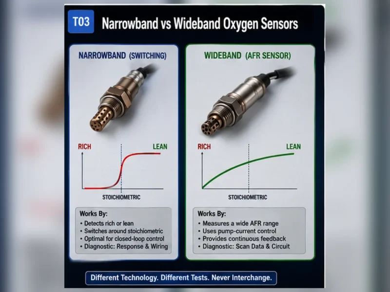
| Technology label | Typical data representation | Selection risk |
|---|---|---|
| Zirconia narrowband | Rich/lean switching voltage under defined conditions | Confused with a wideband sensor that has a different circuit |
| Wideband / A/F | Current, lambda or equivalence-ratio strategy | Marketplace listing calls every heated sensor “wideband” |
| Titania | Resistance/voltage strategy defined by the vehicle | Appearance or wire count is used as identification |
Technology determines heater and signal expectations. Do not probe or substitute circuits based on a generic color chart. A part that threads in and connects can still be electrically incompatible.
Review connector and lead details systematically
Connector face and keying
Compare the mating face, key positions, latch direction and terminal count. Photos should be square to the connector and sharp enough to show keying. Similar housings may contain different terminal assignments, so connector shape is a rejection check rather than final proof.
Cable length and routing clips
Measure along the cable path without stretching. Confirm heat sleeves, grommets and clip positions. A lead that is too short can load the terminals; one that is too long can contact the exhaust or moving components. Direct-fit harnesses should not be cut to compensate for a wrong catalog selection.
Thread, hex and shield
Thread and hex determine installation interface, while shield geometry affects exhaust exposure and clearance. These dimensions must match, but matching them does not prove calibration or circuit compatibility.
When a universal sensor is an appropriate candidate
Consider a universal sensor only when the manufacturer lists the technology and application, supplies an approved environmental splice method and provides clear circuit identification. Universal means the connector is not preinstalled; it does not mean unrestricted vehicle compatibility. Do not reuse a heat-damaged connector or splice close to the exhaust.
| Question | Direct-fit | Universal |
|---|---|---|
| Application connector supplied? | Yes | No; approved transfer/termination required |
| Primary advantage | Reduced installation variables | May cover a defined compatible circuit when supported |
| Primary risk | Wrong catalog position | Circuit or splice error in addition to fitment error |
| Required evidence | Current application match | Application, technology and splice instructions |
Composite scenario: the same model name hides two exhaust systems
Composite engineering scenario: a buyer selects by model and year, but the catalog shows different upstream sensors for two engines and regional emissions configurations. The connector photos look similar. Checking the engine code, emissions label, position and OE number resolves the correct candidate before installation. This is a composite selection pattern, not a Sunhyings fitment claim or customer case.
Verify the delivered part before installation
Match the package number to the order and compare the sensor with the approved record while both remain returnable. Check the label, connector, pins, lead, clips, thread, shield and supplied instructions. Do not contaminate the sensing end or install a part merely to test whether it fits. Photograph discrepancies and stop if the package, catalog and physical part do not agree.
Build a return-prevention record
Keep the catalog result or quotation revision, OE reference, full vehicle identity, emissions label, exact position and comparison photos with the order. For an installation complaint, add the original codes, diagnostic basis, delivered package label and images of connector and routing. This separates a catalog conflict from a circuit fault, installation damage or an unresolved engine condition.
A responsible seller should not convert incomplete information into a guaranteed-fit statement. When a required field is missing, the correct outcome is Pending Fitment Review. The same rule applies to bulk buyers: approve application data by revision and require notification before a supplier expands or changes coverage.
Do not use the fault code as the part number
A code can identify a bank, position, circuit or monitored condition, but it does not encode the connector, cable length, technology or OE reference. P0420/P0430 does not identify a replacement oxygen sensor at all. Record codes as diagnostic evidence, then complete the independent fitment identity before selecting a part.
Keep diagnosis and fitment as separate approvals
The first approval answers whether replacement is justified; the second answers which exact part is compatible. Passing one does not pass the other. This two-gate record reduces the common errors of ordering the right sensor for the wrong position or ordering a perfectly matched part for a fault caused by wiring, leakage or fuel control.
Use a fixed data sequence before searching a catalog
The safest selection sequence begins with vehicle identity and exact exhaust position, then moves to OE/application evidence and finally to physical and electrical confirmation. Starting with a connector photo or trouble code reverses that sequence and encourages visually similar but incompatible choices.
| Step | Required input | Where to obtain it | Stop condition |
|---|---|---|---|
| 1. Vehicle identity | VIN, year, make, model and exact engine | Vehicle, registration and verified decoder/service data | Model/year only where multiple engines exist |
| 2. Market/emissions | Sales region, emissions label/configuration and relevant build breakpoint | Vehicle label and service/application data | Regional configuration unknown |
| 3. Position | Bank and Sensor number relative to catalyst | Cylinder numbering and exhaust diagram | Only “front,” “rear” or physical side supplied |
| 4. Diagnostic basis | Failed test for the named circuit/response | Workshop record and service procedure | DTC or symptom used as proof of failure |
| 5. OE/application | Readable OE number or current controlled mapping | Removed part and verified catalog | Cross-reference with no source/revision |
| 6. Technology | Narrowband, titania or wideband/A/F and circuit | Vehicle and product specification | Wire count used as technology proof |
| 7. Interface | Thread, shield, connector, pins, lead and clips | Drawing and contextual comparison photos | Any unresolved physical conflict |
Treat an OE number as an anchor, not a complete conclusion
A readable OE number from the removed part can strongly anchor the search, but supersessions, prior repairs and market-specific variants still matter. An aftermarket cross-reference is a candidate mapping created by a catalog owner. It does not automatically prove identical electrical behavior, connector, lead or every application row.
| Evidence situation | Action | Reason |
|---|---|---|
| OE number, vehicle and position all agree | Proceed to technology and interface confirmation | Three independent identity layers align |
| OE number maps to two aftermarket parts | Check engine, emissions, VIN breakpoint and position details | Cross-reference may cover variants |
| Removed part number conflicts with vehicle catalog | Investigate prior repair and supersession before ordering | Installed part may be wrong or catalog may be stale |
| Number is unreadable | Use full vehicle/position plus connector and dimensional evidence | Do not invent digits from a blurred mark |
| Marketplace list claims many OE numbers | Request source, revision and part-level specification | Long lists can merge incompatible applications |
Identify sensor technology before comparing wires or price
Zirconia narrowband sensors report around a rich/lean transition. Wideband or air-fuel-ratio sensors use a controlled pump-cell strategy and more complex electronics. Titania designs operate differently from zirconia. The vehicle controller and sensor form a matched system; technology cannot be converted by splicing a different connector.
| Technology clue | What it can indicate | Why it is insufficient alone | Required proof |
|---|---|---|---|
| Number of wires/pins | Heater and signal circuit complexity | Different technologies can share counts | Electrical/product specification |
| Scan-data label | Voltage, current, lambda or A/F representation | Tool may derive or rename values | Service data and supported parameter definition |
| Connector shape | Application family or revision clue | Shell similarity does not prove pinout | Keying, terminal map and OE/application data |
| Position | Upstream often has feedback role | Position does not mandate one technology | Exact vehicle specification |
| Product marketing name | Seller’s category | “Lambda” and “O2” are broad terms | Part-level technical data |
Complete the physical-interface check
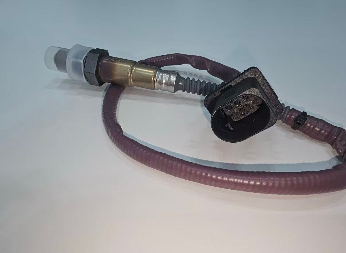
Use clear, same-angle photos and measurements only after the application record is established. Compare the connector face rather than the back of the housing, count and locate terminals, examine keys and locking features, and check lead length along the intended route. Thread diameter alone does not prove the correct pitch, seat, shield or calibration.
| Feature | Evidence | Failure if wrong |
|---|---|---|
| Thread and seat | Drawing/specification and old-part comparison | Damage, leak or inability to seat |
| Hex and body clearance | Dimensions and installed access | Tool/access conflict or contact |
| Shield geometry | Specified design for exhaust position | Clearance or gas-exposure conflict |
| Connector keys/lock | Face photo and controlled drawing | Forced fit or insecure connection |
| Pin assignment | Electrical map and product specification | Wrong signal/heater circuit or damage |
| Lead length/insulation | Measured route, heat rating and strain relief | Stretch, melt or unsupported loop |
| Clips/grommets | Application route and supplied hardware | Chafe, movement or heat exposure |
Direct-fit and universal are different engineering decisions
A direct-fit sensor supplies an application connector and should install without cutting or re-keying the harness. A universal sensor may require an approved connector-transfer or splice procedure, but it still must match technology and circuit. Wire colors are not a universal pinout. If exact compatibility and an environmentally durable joining method are not documented, select a verified direct-fit part.
| Question | Direct-fit answer | Universal answer |
|---|---|---|
| How is fit established? | Controlled vehicle/position catalog plus specification | Technology/circuit compatibility plus manufacturer instructions |
| Connector work | None; do not cut the supplied harness | Only the approved termination method |
| Main installation risk | Wrong application or route | Misidentified circuits, poor seal or unsuitable splice location |
| Warranty record | Part, vehicle, position and installation evidence | Add pin map, splice materials and procedure evidence |
| Stop rule | Any key, lead or application conflict | Any uncertainty in technology, pinout or approved method |
Compare suppliers only after mandatory fitment gates pass
Price, warranty and delivery cannot compensate for an unresolved fitment identity. First require a controlled application table, part specification, validation evidence, production control and traceability. Then compare commercial terms for candidates that pass.
| Evidence layer | Buyer question | Weak substitute |
|---|---|---|
| Application governance | Who owns sources, revisions, supersessions and conflicts? | Unversioned fitment spreadsheet |
| Part specification | Are technology, heater, interface and materials defined? | Photo and OE list only |
| Validation | Which identified samples, methods, criteria and results? | Test-name list without reports |
| Production control | Which checks are 100% and which are sampled? | Equipment photographs |
| Traceability/change | Can lot/revision be traced and changes notified? | Certificate logo on packaging |
| Claims | What evidence supports OEM approval or certification wording? | “OEM quality” marketing phrase |
Composite case: OE cross-reference and connector evidence conflict
Composite procurement scenario: two supplier catalogs map the same OE candidate to different connectors. The buyer does not choose the cheaper listing. Vehicle engine, emissions configuration and exact position are confirmed, then connector drawings and application revisions are requested. One mapping belongs to a different market variant and is removed from the quote.
The example shows why a cross-reference is a candidate, not interchangeability proof. It is composite and does not describe a Sunhyings supplier or customer.
Composite workshop case: a universal sensor is rejected before splicing
Composite workshop scenario: a universal sensor has the same number of wires as the removed wideband unit, but the documentation does not identify compatible technology or pin functions. The installer stops rather than match colors. A verified direct-fit sensor with the correct connector, lead and application record is selected.
The decision avoids experimenting on an emissions-control circuit. It does not claim that every universal sensor is unsuitable; it shows that universal fit requires documented electrical compatibility and an approved joining method.
Final selection record before purchase
- Vehicle, engine, VIN/build and market/emissions identity
- Bank/Sensor position and diagnostic basis
- OE number or controlled cross-reference source and revision
- Technology and electrical/heater requirements
- Thread, shield, connector, pins, lead and clips
- Direct-fit or universal installation method
- Supplier specification, validation, traceability and warranty evidence
- Any unavailable information marked
DATA NOT AVAILABLEand held open
Resolve catalog conflicts before approving the order
Conflicts are not rare exceptions to hide. They are signals that the selection record is incomplete, a source is stale or the application has a genuine variant. Create a hold state rather than letting the sales channel choose whichever row produces a result.
| Conflict | Likely investigation | Approval evidence | Do not do |
|---|---|---|---|
| Two OE numbers for one vehicle/position | Supersession, build/VIN or emissions variant | Current source showing which condition selects each | List both as universally interchangeable |
| Two connectors under one aftermarket SKU | Catalog merge or product revision | Drawing/revision and application split | Ship randomly and let installer adapt |
| Old part differs from catalog result | Prior wrong repair, supersession or configuration error | Service/application reconciliation | Assume the installed part is original |
| Lead length differs | Wrong bank/position or route revision | Installed-route measurement and controlled drawing | Stretch, extend or tie excess near heat |
| Technology descriptions conflict | Terminology, catalog or cross-reference error | Electrical specification for vehicle and candidate | Choose by wire count |
| Certificate scope differs from sales claim | Wrong legal entity/site or overbroad claim | Correct certificate plus part-level evidence | Use the logo as SKU approval |
Record the conflict owner, sources reviewed, decision, date and affected rows. If the source cannot be resolved, mark the mapping blocked. This prevents the same uncertainty from reappearing in ecommerce, quotation, warehouse picking and warranty analysis.
A sample approval must test product, application data and packaging together
A sensor that threads into one bung has not passed a complete sample review. Define the candidate part/revision, exact applications and positions, sample lot and acceptance criteria before inspection. The approved sample must be traceable to the later production design, process and site or changes must trigger review.
| Sample area | Inspection or test | Pass evidence | Failure action |
|---|---|---|---|
| Identity | Part, revision, lot/date and package linkage | All records name the same product | Quarantine unidentified sample |
| Application | OE/YMME/engine/emissions/position source review | Approved rows with revision | Block conflicting rows |
| Physical interface | Thread, shield, connector, pins, lead and clips | Drawing and measured sample agree | Correct product or drawing |
| Electrical/function | Defined heater and technology-specific response tests | Method, criteria, results and equipment trace | Investigate; do not waive by appearance |
| Vehicle evaluation | Exact engine/emissions/position and safe service method | Documented fit, route and legal monitor result | Stop if identity or method is uncertain |
| Label/barcode | Scan in receiving and picking workflow | Correct part, quantity, language and trace fields | Correct artwork/data before launch |
| Change linkage | Compare sample design/process/site to production plan | Notification and revalidation terms agreed | Approval not transferable to unknown production |
Verify selection again at receiving and installation
Catalog approval does not remove packing or picking risk. At receiving, compare label, part, lot/date and packaging with the purchase record. Before installation, compare the old and new part in context and confirm the application/position record. Keep protective caps in place until installation and prevent contamination of the sensing end.
If the connector, lead, thread or shield conflicts, do not modify the part. Photograph the complete mismatch, preserve labels and request a data/product investigation. Separating catalog error, packing error and product nonconformance improves corrective action and protects valid inventory.
RFQ template for an exact oxygen-sensor selection
| RFQ section | Required content |
|---|---|
| Market and channel | Sales countries, retail/workshop/distributor/private label and launch scope |
| Part list | OE candidates, customer part numbers and exact Bank/Sensor positions |
| Application | YMME, engine, emissions/region, VIN breakpoints and data-source requirements |
| Product | Technology, heater/electrical, thread, shield, connector, pins, lead and clips |
| Approval | Samples, dimensions, electrical/response/durability tests and documents |
| Quality | Traceability, inspection, nonconformance, change notification and claim process |
| Commercial | Forecast by part, quantity, Incoterm, destination, packaging and requested timing |
Sunhyings can review a submitted RFQ for sourcing feasibility. The existence of this process does not confirm stock, fitment, price, MOQ, lead time or certification for an unreviewed part number.
Common selection failures and the evidence that prevents them
| Failure | Why it happens | Prevention |
|---|---|---|
| Correct model, wrong engine | Catalog search stops at year/make/model | Require engine code/VIN and emissions configuration |
| Correct engine, wrong position | Bank/Sensor field omitted | Map cylinder 1 and catalyst relationship |
| Connector fits, circuit differs | Housing appearance treated as electrical proof | Verify technology, pins and specification |
| Lead melts or stretches | Length and clips excluded from fitment | Compare complete installed route |
| Code remains after installation | Code used as diagnosis or vehicle fault remains | Complete circuit/system tests before order |
| Sample passes but production changes | No change notification or revision linkage | Contractual notification and revalidation control |
The best selection process is deliberately conservative: a held order is preferable to a modified harness, damaged connector or repeat emissions repair. When exact information is missing, ask for it and preserve the unanswered field. Do not let an ecommerce interface silently replace unknown engine, position or emissions data with a broad default.
After installation, confirm that the selected part follows the original routing, the connector locks, the exhaust is sealed and the technology-specific response is plausible. Complete the applicable legal monitor. If the original code returns, reopen diagnosis and selection records rather than assuming either that the new sensor is defective or that the catalog match proves the vehicle has no other fault.
For a distributor, feed every confirmed catalog conflict back to the controlled application database and affected inventory. A corrected return without a data correction leaves the same error active for the next buyer.
The final purchase authorization should name the exact approved part and revision, not only a supplier family. If any mandatory identity field changes before shipment, reopen the selection check rather than carrying approval forward automatically.
Prepare a fitment or sourcing request
Send the OE number, year/make/model, engine or VIN details, market and emissions package, exact bank/sensor position, connector and old-part photos, quantity and any packaging or approval requirements. Sunhyings will review the supplied data for capability and sourcing feasibility; fitment is not confirmed until application evidence is matched.
Frequently asked questions
Can I choose an oxygen sensor by vehicle model only?
Not reliably. Engine, market or emissions package and exact bank/sensor position can change the required part.
Is the OE number enough?
It is the strongest starting point, but check supersessions and confirm it against the vehicle, market, position and current catalog data.
Does the same connector mean the sensor fits?
No. Connector appearance does not prove the same calibration, technology, cable routing or exhaust position.
Is a universal oxygen sensor suitable for every car?
No. Universal describes the termination method, not universal vehicle compatibility. Follow the sensor manufacturer’s application and splice instructions.
What photos help verify fitment?
Clear photos of the old-part label, threaded body, connector face and keying, full cable and routing clips are useful alongside vehicle and OE data.