Oxygen Sensor Technical Guide
Learn how upstream and downstream oxygen sensors support closed-loop fuel control and catalyst monitoring, and why system diagnosis matters.
Quick answer
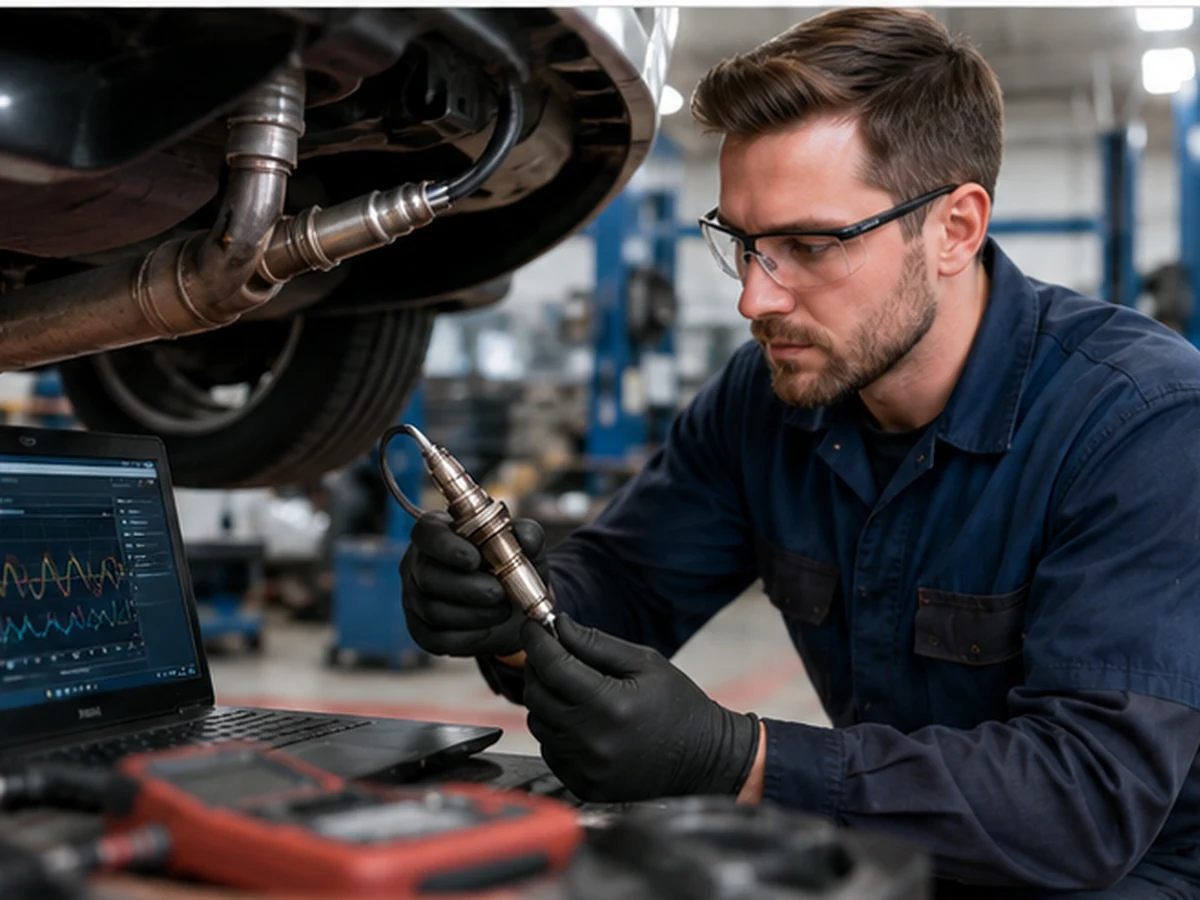
Upstream oxygen sensors provide exhaust feedback that helps the engine control module maintain intended air-fuel control after warm-up. Downstream sensors commonly help evaluate catalyst performance. Accurate feedback can support fuel efficiency and emissions control, but the result depends on the complete engine, fuel, ignition, exhaust and catalyst system—not the sensor alone.
Closed-loop fuel control
The control module begins with calibrated airflow, fuel and temperature information. Once required conditions are met, oxygen-sensor feedback helps it evaluate whether combustion is trending rich or lean and adjust short-term correction. Longer-term adaptation may compensate for repeated trends. A biased sensor can mislead this process, but a healthy sensor can also report a genuine intake, fuel or combustion fault.
Catalyst monitoring
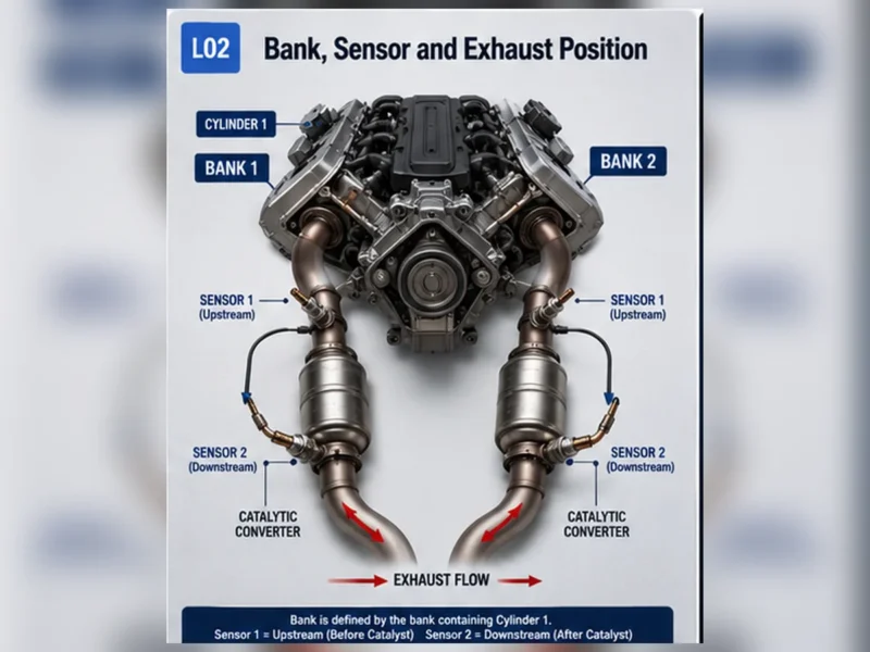
A catalyst stores and releases oxygen as it converts regulated exhaust constituents. The control strategy compares upstream and downstream behavior under defined conditions to evaluate the system. The rear signal is therefore evidence about the catalyst system, not a simple “good sensor/bad sensor” output. Exhaust leaks, misfire, mixture faults and sensor bias can affect the monitor.
Why correct feedback can support fuel economy
Fuel economy is affected by load, speed, temperature, tires, aerodynamics and driver behavior. Within that larger system, correct mixture feedback helps avoid unnecessary rich or lean correction during closed-loop operation. No responsible estimate can promise a universal percentage improvement from replacing a sensor; the part must first be proven faulty.
Conditions that distort the feedback loop
| Condition | Potential effect |
|---|---|
| Intake or exhaust leak | Creates oxygen readings that do not represent commanded mixture. |
| Misfire | Leaves oxygen and unburned fuel in the exhaust and can overheat the catalyst. |
| Fuel-delivery fault | Forces trims while the sensor may be reporting correctly. |
| Contamination or thermal damage | Can slow or bias sensor response. |
| Wiring/heater fault | Prevents the sensor from reaching or reporting the required condition. |
Repair, do not bypass
Spacers, simulators, sensor deletes and software changes that conceal catalyst monitoring are not substitutes for diagnosis and may violate emissions law. Record diagnostic evidence, repair the root cause, confirm sensor and catalyst behavior, and complete the applicable readiness procedure.
The oxygen sensor is one part of a control loop
The control module begins with airflow or load, temperature, speed and calibrated fuel information. Once enable conditions are met, upstream oxygen-sensor feedback helps it evaluate mixture and apply correction. Combustion, catalyst condition, leaks and other inputs determine the resulting emissions. The sensor reports evidence; it does not remove pollutants by itself.
| System element | Primary contribution | Failure boundary |
|---|---|---|
| Air/load measurement | Initial fuel calculation | Bias can create false mixture demand |
| Upstream sensor | Mixture feedback | May report a real air/fuel fault accurately |
| Ignition/combustion | Burns the commanded mixture | Misfire changes oxygen and fuel in exhaust |
| Catalyst | Converts regulated exhaust constituents | Needs valid temperature and mixture operation |
| Downstream sensor | Commonly monitors catalyst behavior | Signal requires engine/leak/catalyst context |
Closed loop depends on operating state
Cold start and warm-up
The control system may use programmed fueling while sensors and catalyst warm. Heater circuits shorten the time to useful feedback, but a cold reading should not be compared with warm specifications.
Warm idle and cruise
When criteria are met, short-term correction responds to feedback and long-term adaptation can represent repeated trends. Intake leaks, fuel delivery and airflow errors can drive correction while the sensor remains accurate.
Acceleration and deceleration
Commanded enrichment, open-loop operation or fuel cut can create readings that would appear abnormal at steady cruise. Diagnosis must record load and commanded state.
| State | Possible control behavior | Diagnostic caution |
|---|---|---|
| Cold start | Programmed fueling and warm-up | Feedback may not be enabled |
| Warm steady cruise | Closed-loop correction | Compare only stable supported data |
| High load | Strategy-specific enrichment | Rich indication may be commanded |
| Deceleration | Fuel cut under defined conditions | High exhaust oxygen may be expected |
How downstream feedback supports catalyst monitoring
A catalyst stores and releases oxygen as it converts exhaust constituents. Under defined monitor conditions, the control module evaluates upstream and downstream behavior. The result concerns the catalyst system. Exhaust leaks, misfire, fuel-control faults, sensor bias and catalyst deterioration can influence it. P0420/P0430 therefore requires system diagnosis.
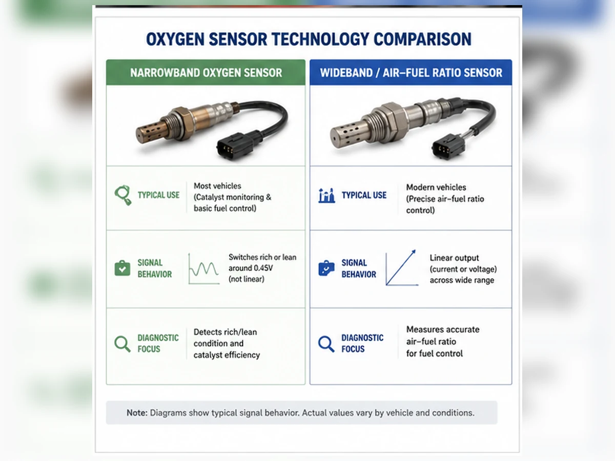
Sensor technology changes the feedback representation
Narrowband feedback
A zirconia narrowband sensor is commonly used around a rich/lean switching region. It is not a laboratory emissions analyzer and should not be assigned a pollutant concentration from one voltage.
Wideband/A/F feedback
A wideband system can represent mixture over a broader range using a controlled current/lambda strategy. It requires the matching control circuit and service interpretation. Substituting a narrowband sensor is not a legal or technical shortcut.
Downstream design
Downstream sensors are often narrowband, but the application record controls. Position, technology and calibration must be verified rather than inferred from the common role.
Conditions that distort emissions feedback
| Condition | Sensor evidence | System consequence |
|---|---|---|
| Intake leak | Lean indication/positive correction | Feedback may be correct; air path needs repair |
| Exhaust leak | Outside oxygen affects reading | Fuel/catalyst interpretation becomes unreliable |
| Misfire | Oxygen and unburned fuel reach exhaust | Catalyst can overheat or be damaged |
| Rich fuel fault | Rich indication/negative correction | Fuel use and catalyst load increase |
| Contaminated sensor | Slow or biased response | Feedback can mislead control |
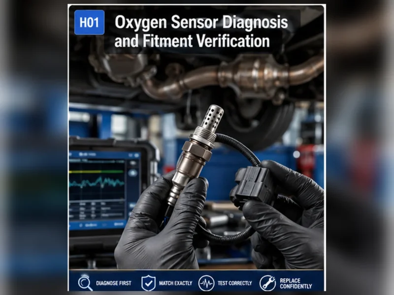
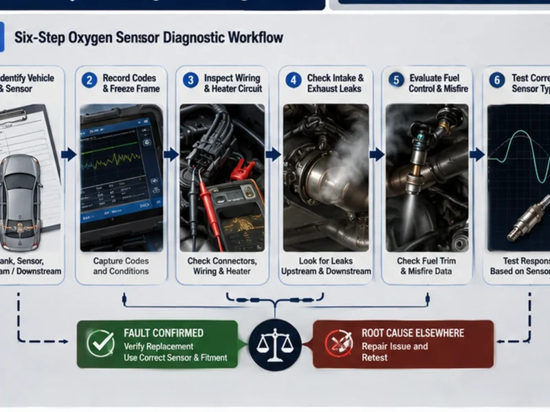
Diagnosis before an emissions-related replacement
- Record codes, freeze frame and readiness.
- Resolve active misfire and safety faults first.
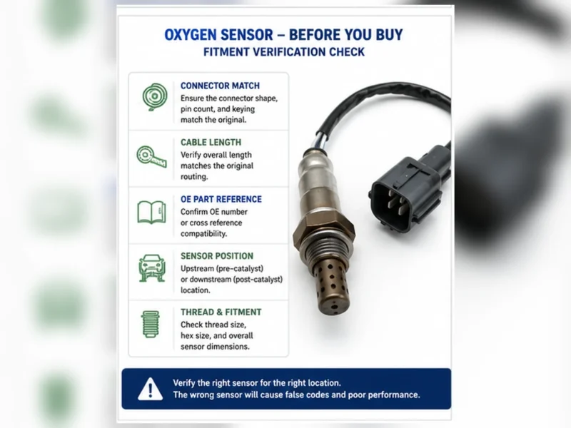
- Confirm bank, position and sensor technology.
- Inspect intake/exhaust leakage and harness routing.
- Test heater/circuit and compare trims with response.
- Follow the catalyst procedure when efficiency codes remain.
Do not replace the downstream sensor merely because an inspection failed or P0420/P0430 is present. Do not clear codes repeatedly to create temporary readiness status. Repair evidence must match the monitor that failed.
Repair rather than bypass
Spacers, defoulers, simulators, sensor deletes and software strategies that conceal catalyst monitoring do not repair the engine, sensor or catalyst. They can violate emissions law. “Off-road use” is not a universal exemption. Follow applicable EPA/CARB or local rules and restore the designed monitoring system.
Why this page makes no universal reduction claim
Replacing a proven faulty sensor can restore intended feedback, but the emissions result depends on the original failure, engine, fuel, ignition, exhaust and catalyst condition and test cycle. Without controlled before/after data, no percentage reduction or fuel-saving promise is supportable. A functioning sensor in a faulty system cannot guarantee compliance.
Composite scenario: the sensor correctly reports a rich engine
Composite diagnostic scenario: an upstream sensor reports rich and fuel trims subtract fuel. Testing identifies excessive fuel pressure. Replacing the sensor would remove the reporter but not the cause; correcting fuel pressure restores plausible control and protects the catalyst. This is a composite teaching example, not a Sunhyings case or emissions result.
Verify system operation after repair
Confirm physical installation, heater/circuit function, technology-specific response, fuel trims and exhaust sealing. Then complete the applicable readiness monitor under legal and safe conditions. Permanent codes may remain until a passing monitor confirms the repair. Keep before/after data rather than treating an extinguished warning light as the sole result.
Emissions inspection and readiness are not the same as one sensor reading
An inspection program may evaluate OBD readiness, stored or permanent codes and other jurisdiction-specific requirements. A sensor that displays data does not prove that the relevant monitors are complete or that the vehicle meets the applicable standard. After battery disconnection or code clearing, monitors may be Not Ready until defined conditions occur.
Do not perform unsafe or illegal driving solely to force a monitor. Follow manufacturer service information and local inspection rules. If a monitor will not complete, check enable criteria, related codes, temperatures and repaired-system data instead of installing a bypass device.
Evidence boundaries for product and supplier claims
A replacement listing can describe verified technology, OE cross-reference, application and position. It cannot responsibly promise that installing the part will make every vehicle pass inspection or reduce emissions by a fixed amount. Those outcomes depend on complete vehicle condition and regulated test procedures.
For distributor sourcing, request controlled application data, electrical and response specifications, validation methods, lot traceability and change control. A management-system certificate does not prove vehicle-specific emissions performance, and an OE-supplier claim must be verified at the exact legal entity and product scope.
Any compliance statement should name the applicable market and evidence. Regulations, inspection procedures and vehicle configurations differ; a general educational page cannot certify a specific repair outcome. Related faults and monitor enable criteria must also be resolved before the system result can be interpreted.
Prepare a fitment or sourcing request
Send the OE number, year/make/model, engine or VIN details, market and emissions package, exact bank/sensor position, connector and old-part photos, quantity and any packaging or approval requirements. Sunhyings will review the supplied data for capability and sourcing feasibility; fitment is not confirmed until application evidence is matched.
Frequently asked questions
Do oxygen sensors reduce emissions?
They provide feedback used by the control system; emissions performance depends on the complete engine, fuel, ignition, exhaust and catalyst system.
Does the downstream sensor control fuel economy?
Its primary role is commonly catalyst monitoring, although strategies vary. Diagnose the specific vehicle rather than assuming direct fuel control.
Can a faulty sensor damage the catalytic converter?
Incorrect mixture control or an unresolved engine fault can contribute to catalyst damage; diagnose the root cause promptly.
Will a new sensor guarantee better mileage?
No. It helps only when the old sensor is faulty and influencing control, and other mileage factors remain.
Can a spacer fix a catalyst code?
No. It can conceal monitor behavior and may violate emissions law; it does not repair the catalyst or root cause.