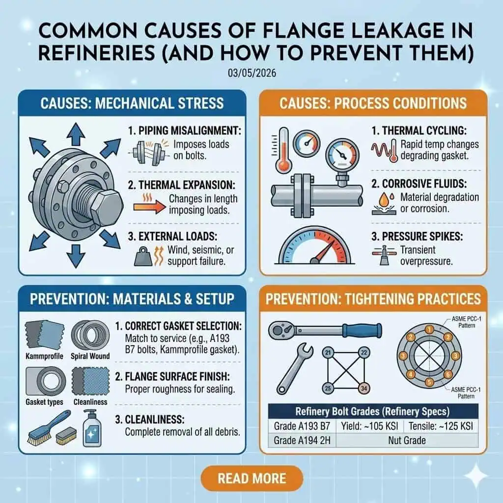
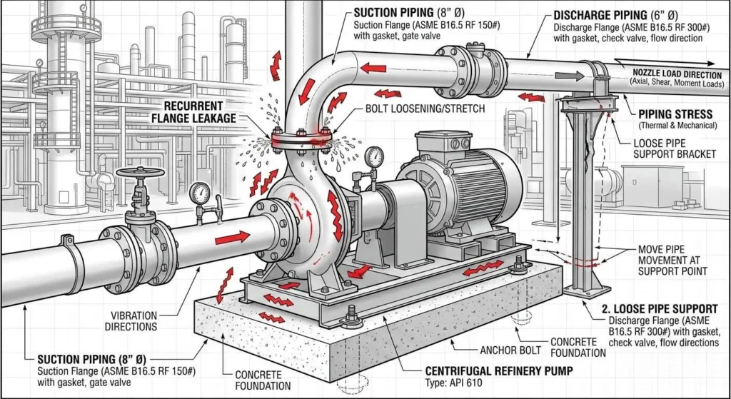
What causes flange leaks in refineries? The most common causes are wrong gasket selection, uneven bolt preload, flange misalignment, damaged flange faces, vibration, pipe stress, corrosion, and poor maintenance traceability. In refinery service, flange leakage rarely comes from one mistake alone. A joint may survive hydrotest and still leak after startup because the gasket, bolts, facing, alignment, and operating loads were never controlled as one system.
Direct answer: Most refinery flange leaks start with assembly errors, but repeated or hard-to-stop leaks usually involve a second layer of causes such as thermal cycling, external piping load, vibration near pumps, corrosive service, or undocumented gasket and material substitution during shutdown work.
- Wrong gasket material, thickness, size, or facing compatibility
- Uneven bolt tightening and low or unstable preload
- Flange misalignment or using bolts to pull piping into place
- Scratched, corroded, dirty, or residue-covered sealing faces
- Vibration, nozzle loads, poor support placement, or thermal movement
- Corrosion, erosion, and service-related degradation
- Missing MTR, PMI, torque, or joint history records after maintenance
For refinery teams, the practical goal is not just to stop the visible leak. The goal is to identify the dominant flange leak cause, correct the system-level contributors, and prevent the same joint from leaking again at the next startup.
What Causes Flange Leaks in Refineries?
Refinery flange leakage usually starts in one of six places: gasket choice, bolt preload, flange alignment, face condition, external load, or service-related degradation. The leak becomes harder to solve when documentation is weak, because teams no longer know which gasket was used, how the joint was tightened, or whether material substitution happened during the last turnaround.
| Common Flange Leak Cause | Why It Creates Leakage | Typical First Check |
|---|---|---|
| Wrong gasket selection | Gasket cannot maintain sealing stress under actual media, temperature, pressure, or facing condition | Verify gasket type, material, thickness, size, and facing match |
| Uneven bolt preload | Non-uniform compression unloads the gasket and opens leak paths | Review tightening sequence, lubrication condition, and assembly record |
| Flange misalignment | Bolts carry alignment load instead of gasket seating load | Check face gap, bolt-hole fit, spool stress, and support condition |
| Damaged or dirty flange face | Scratches, rust, residue, or debris interrupt sealing contact | Inspect gasket band before reassembly |
| Vibration and piping stress | External load changes bolt tension and distorts the joint during operation | Check supports, nearby rotating equipment, and vibration history |
| Corrosion or material mix-up | Wrong material or degraded components lose integrity in service | Review MTR, PMI, markings, and service compatibility |
How Gasket Problems Cause Flange Leakage
Improper gasket selection is one of the most common flange leak causes in refineries. A gasket may look dimensionally correct and still fail if the material does not match the service chemistry, temperature range, pressure class, flange facing, or compression requirements. This is especially common after shutdown work when visually similar gasket types are substituted without engineering review.
In refinery practice, gasket failure often shows up in one of these patterns:
- Leak starts after startup because the gasket relaxes under heat and preload drops
- Leak appears in sour, wet, or chemically aggressive service because the gasket material is incompatible
- Leak repeats after every turnaround because the same non-approved replacement keeps being installed
- Leak shows up only under cycling because the selected gasket cannot recover under thermal movement
Before installation, teams should verify the gasket against the joint design, not only the flange size. That includes service media, operating and upset temperature, pressure, facing type, and approved maintenance list. If you are reviewing replacement practice, this related guide on flange gasket selection and service compatibility is a useful cross-check.
Field example: A refinery startup leak on a hot hydrocarbon line was traced to a gasket that matched the flange dimensions but not the approved material grade for thermal cycling. The joint sealed during static checks, then leaked once temperature equalization and preload relaxation occurred.
How Bolt Preload Loss Causes Flange Leaks
Many refinery flange leaks are preload problems, not “torque problems.” A flange can leak even when the recorded torque value looks correct, because torque is only an indirect way to create bolt tension. Lubrication condition, friction scatter, embedment, thermal settlement, and vibration all affect how much real clamping force remains after startup.
- Uneven tightening creates localized low-load zones around the gasket
- Over-tightening can damage the gasket and accelerate relaxation
- Under-tightening leaves too little seating stress from the start
- Different lubrication conditions between bolts create preload scatter even at the same torque
- Thermal cycling and vibration can reduce effective bolt tension after startup
Critical refinery joints should be assembled with staged tightening, a defined sequence, calibrated tools, and verification steps. Where procedures require it, advanced bolting methods or hydraulic tensioning can improve consistency on large or high-consequence joints. For related assembly control, see this flange assembly guide for zero-leakage joint integrity.
Practical reminder: When a flange leaks after startup, do not look only at the final torque number. Check preload retention, lubricant consistency, gasket compression pattern, and whether operating loads changed the joint after assembly.
Can Misalignment and Pipe Stress Cause Flange Leaks?
Yes. Flange misalignment and external piping load are major causes of repeat leakage. If a spool is pulled into place with bolts, part of the bolt load is consumed by bending and forced fit-up instead of gasket compression. The joint may look closed, but preload is already being used to fight misalignment. Once the line heats up, vibrates, or moves, the gasket unloads locally and the leak begins.
- Angular misalignment causes uneven face loading
- Parallel offset creates non-uniform gasket seating
- Poor supports transfer piping stress into the flange
- Pump or compressor vibration accelerates preload loss
- Nozzle load can distort the joint even when the flange itself is correct
Field example: A pump suction flange leaked repeatedly despite multiple gasket changes. The actual cause was poor support stiffness and vibration. Once the support condition and piping alignment were corrected, the flange stopped leaking.
How Damaged Flange Faces Cause Leakage
A damaged flange face can create immediate leak paths even when the gasket and bolt load are correct. Scratches, corrosion pits, old gasket residue, overspray, weld spatter, rust, or dirt interrupt the contact band and prevent even sealing. In refinery environments, shutdown work and storage conditions often introduce face damage long before the joint is reassembled.
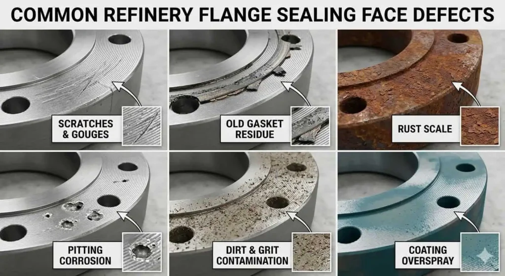
- Old gasket residue creates high spots and uneven compression
- Radial scratches can become direct leak channels
- Corrosion pits reduce real contact area in the gasket band
- Dirty faces prevent stable gasket seating from the first tightening pass
If your team is seeing repeated leakage after maintenance, always inspect the sealing band before assuming the new gasket is at fault. For broader prevention practice, see common flange leakage causes and preventive measures.
How Corrosion and Material Mix-Up Cause Leaks
Corrosion and traceability failures often turn a small flange leak into a repeat shutdown issue. In refinery service, corrosion may attack the flange face, the bolting, or the gasket environment. At the same time, maintenance work can introduce wrong materials if receiving checks and traceability controls are weak.
- Wrong flange or bolt material may corrode faster than expected in service
- Incorrect gasket material may harden, swell, embrittle, or chemically degrade
- Missing MTR or PMI records make root cause analysis slower and less reliable
- Material substitution during turnaround work can go unnoticed without proper marking checks
Critical joints should be backed by heat-lot traceability, clear markings, and material verification records where required. A useful companion page here is how to read flange markings and traceability information.
Why Flange Leaks Repeat After Startup or Turnaround
Flange leaks often repeat after startup because the original repair only addressed the visible symptom. Teams replace the gasket, retighten bolts, or change one component, but the underlying drivers remain: misalignment, vibration, thermal preload loss, damaged faces, or poor documentation of what was installed last time.
- Startup heat-up changes flange alignment and preload retention
- Gasket embedment and settling reduce clamping force after initial operation
- Turnaround schedule pressure can lead to substitution and incomplete final checks
- Weak leak history records allow the same mistake to be repeated on the same joint
| Observed Leak Timing | Typical Root Cause Pattern | Best First Review |
|---|---|---|
| Leak appears shortly after startup | Preload loss, gasket centering error, thermal settlement | Assembly record, gasket type, tightening sequence, lubrication condition |
| Leak returns after every turnaround | Wrong replacement practice, poor face prep, unresolved misalignment | Joint history log, parts used, face inspection standard |
| Leak grows with vibration or flow change | External piping load or support problem | Support layout, alignment, vibration trend |
| Leak shows slowly in corrosive service | Material incompatibility, corrosion, or face damage progression | Material records, service chemistry, inspection history |
How to Troubleshoot a Flange Leak
Start with Leak Pattern and Service Context
The fastest way to troubleshoot a flange leak is to capture the leak pattern before disturbing the joint. Note whether the leak is seepage, drips, vapor, stain-only, intermittent during thermal change, or related to equipment vibration. Record the joint ID, service, startup status, recent maintenance, and any known support or alignment issue.
Important: This article is an engineering troubleshooting guide, not a live-work instruction. Always follow refinery isolation, permit, gas testing, mechanical integrity, and emergency response procedures before inspection, loosening, tightening, or disassembly.
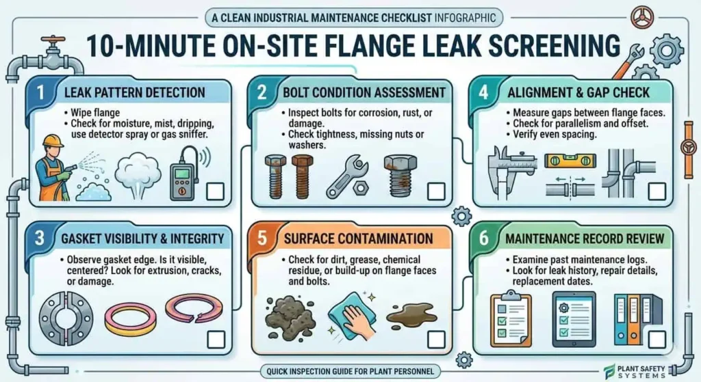
10-Minute On-Site Screening Checklist
| Step | What to Check | Why It Matters |
|---|---|---|
| 1 | Leak pattern and location | Helps separate gasket-face, bolt, weld-adjacent, and vibration-related leaks |
| 2 | Bolt condition and visible loading clues | Corrosion, loose hardware, washer position, missing witness marks can indicate preload problems |
| 3 | Gasket clues if visible | Off-center placement or squeeze-out suggests centering or compression problems |
| 4 | Alignment and support condition | Face-gap variation, nozzle stress, loose supports, and vibration often drive repeat leaks |
| 5 | Surface contamination evidence | Rust, residue, dirt, overspray, or prior gasket material often explains startup leaks |
| 6 | Recent maintenance and documentation | Missing torque, gasket, MTR, or PMI records raise substitution and repeat-failure risk |
What to Check After Isolation or Shutdown
Root cause confirmation should be based on physical evidence, not memory. After the system is safely isolated, inspect gasket compression marks, flange face condition, bolt threads and washers, support condition, and nearby weld zones where applicable. Photograph the joint before cleaning so you do not lose evidence of residue transfer, uneven compression, or leak direction.
- Check gasket compression pattern for uneven load or off-center seating
- Inspect flange faces for scratches, pitting, corrosion, or residual gasket material
- Review bolts, studs, nuts, and washers for corrosion, galling, or inconsistent lubrication clues
- Confirm material identity and documentation if substitution is suspected
- Compare findings with previous leak history for the same joint ID
What Not to Do When Troubleshooting a Flange Leak
- Do not assume every leak is a gasket-only problem
- Do not use bolts to force piping into alignment
- Do not substitute gasket materials by appearance or size alone
- Do not skip documenting joint ID, assembly method, and materials used
- Do not damage the sealing face while cleaning it
- Do not ignore vibration, support, or piping load at recurring leak locations
How to Prevent Flange Leaks in Refineries
Correct Selection at Design and Procurement Stage
Leak prevention starts long before the flange is assembled. Engineers and buyers should confirm flange type, class, facing, material, gasket compatibility, bolting, and service envelope before parts are released to site. A correct flange size is not enough if the joint design basis is wrong.
- Match flange type and facing to service severity and maintenance strategy
- Verify gasket compatibility with media, pressure, and temperature
- Confirm bolting grade and assembly requirements
- Review material records, markings, and traceability before installation
For incoming inspection and supplier review, this page on quality control checks for flanges can help tighten procurement control.
Installation Quality Control and Assembly Discipline
Strict assembly discipline is the fastest practical way to reduce flange leakage. Clean the sealing faces, verify the gasket, center it correctly, align the flanges before loading the bolts, and use staged tightening with calibrated tools. For critical joints, record the assembly method and verification result by joint ID.
- Inspect and clean the sealing face before assembly
- Confirm gasket type, size, and service match
- Center the gasket before final loading
- Verify alignment before tightening
- Use staged tightening and a controlled sequence
- Record the joint ID, method, date, and critical observations
Inspection, Maintenance, and Leak History Tracking
Repeat leaks usually stop only when the joint history is tracked. Refinery teams should log leak-prone joints by ID, record startup observations, compare recurring locations, and tie each event back to the parts installed and the assembly method used. This makes turnaround planning smarter and root cause analysis faster.
- Track recurring leak locations by joint ID
- Review startup leak trends after shutdowns
- Inspect supports and vibration at repeat-leak joints
- Keep MTR, PMI, gasket, and assembly records linked to the joint
Supplier Quality and Traceability Controls
Supplier quality matters because refinery leak investigations often end in a documentation gap. Buyers should verify supplier quality systems, material traceability, product markings, and inspection records before installation. Certified and traceable products reduce uncertainty, especially in high-consequence joints.
| Checklist Item | Why It Matters |
|---|---|
| Supplier quality system | Confirms controlled manufacturing and documentation practice |
| MTR review | Verifies chemical and mechanical properties against the specification |
| Heat-lot traceability | Links the installed item to records for audits and failure analysis |
| PMI or additional checks where required | Reduces material mix-up risk in critical service |
| Assembly record by joint ID | Supports repeat-failure diagnosis after startup or maintenance |
If your team is reviewing component identity and QA records, these internal references also fit naturally in the workflow: flange markings and traceability and flange assembly for zero leakage.
Technical Standards and References
Project specifications and site procedures remain the governing documents. The following standards are commonly relevant when selecting, assembling, inspecting, or troubleshooting refinery flange joints:
- ASME PCC-1 — bolted flange joint assembly guidance
- ASME B16.5 — pipe flanges and flanged fittings
- ASME B16.47 — large diameter steel flanges
- API 570 — piping inspection code
- EPA LDAR guidance — leak detection and repair context for emissions-sensitive facilities
Important: This page is an engineering content guide. It does not replace your refinery work instruction, permit-to-work rules, isolation procedure, bolting standard, or project specification.
FAQ
What causes flange leaks after startup?
Most flange leaks after startup are caused by preload loss, gasket seating problems, misalignment, or unresolved external loads. A joint may look fine during assembly but start leaking after thermal expansion, vibration, or gasket embedment reduces the effective sealing stress.
Can flange misalignment cause leakage?
Yes. Flange misalignment is a major cause of refinery flange leakage. When bolts are used to pull flanges into position, part of the bolt load is lost to alignment correction. That reduces gasket compression and creates local leak paths during operation.
Why do flange bolts seem to loosen after startup?
Bolt preload can drop after startup due to embedment, thermal cycling, vibration, and lubrication-related preload scatter. What looks like “loose bolts” is often a preload-retention problem rather than a simple torque problem.
Can a damaged flange face cause leakage?
Yes. Scratches, pitting, corrosion, dirt, and old gasket residue can all cause flange leaks. Even a correct gasket and correct bolt load may fail if the sealing face is damaged or contaminated in the gasket contact band.
What gasket mistakes cause flange leakage?
The most common gasket mistakes are wrong material, wrong facing compatibility, wrong size, off-center installation, and unapproved shutdown substitution. In refinery service, these errors often show up as leaks after startup or under temperature cycling.
Can vibration cause refinery flange leaks?
Yes. Vibration can unload the gasket, shift the joint, and reduce bolt preload over time. Repeat leaks near pumps, compressors, and poorly supported lines should always trigger a vibration and support review.
Should you retighten a leaking flange in service?
Do not assume in-service retightening is safe or allowed. Pressurized or hazardous refinery systems must follow site procedures, engineering review, isolation requirements, and emergency response rules. Many leaks require controlled shutdown and root cause correction rather than more tightening.
What records should be kept for flange traceability?
At minimum, keep MTRs, markings or heat-lot traceability records, PMI records where required, gasket identification, and assembly records linked to the joint ID. These records make failure investigation and repeat-leak prevention much faster and more reliable.
What causes flange leaks in refineries? The most common causes are wrong gasket selection, uneven bolt preload, flange misalignment, damaged flange faces, vibration, pipe stress, corrosion, and poor maintenance traceability. In refinery service, flange leakage rarely comes from one mistake alone. A joint may survive hydrotest and still leak after startup because the gasket, bolts, facing, alignment, and operating loads were never controlled as one system.
Direct answer: Most refinery flange leaks start with assembly errors, but repeated or hard-to-stop leaks usually involve a second layer of causes such as thermal cycling, external piping load, vibration near pumps, corrosive service, or undocumented gasket and material substitution during shutdown work.
- Wrong gasket material, thickness, size, or facing compatibility
- Uneven bolt tightening and low or unstable preload
- Flange misalignment or using bolts to pull piping into place
- Scratched, corroded, dirty, or residue-covered sealing faces
- Vibration, nozzle loads, poor support placement, or thermal movement
- Corrosion, erosion, and service-related degradation
- Missing MTR, PMI, torque, or joint history records after maintenance
For refinery teams, the practical goal is not just to stop the visible leak. The goal is to identify the dominant flange leak cause, correct the system-level contributors, and prevent the same joint from leaking again at the next startup.
What Causes Flange Leaks in Refineries?
Refinery flange leakage usually starts in one of six places: gasket choice, bolt preload, flange alignment, face condition, external load, or service-related degradation. The leak becomes harder to solve when documentation is weak, because teams no longer know which gasket was used, how the joint was tightened, or whether material substitution happened during the last turnaround.
| Common Flange Leak Cause | Why It Creates Leakage | Typical First Check |
|---|---|---|
| Wrong gasket selection | Gasket cannot maintain sealing stress under actual media, temperature, pressure, or facing condition | Verify gasket type, material, thickness, size, and facing match |
| Uneven bolt preload | Non-uniform compression unloads the gasket and opens leak paths | Review tightening sequence, lubrication condition, and assembly record |
| Flange misalignment | Bolts carry alignment load instead of gasket seating load | Check face gap, bolt-hole fit, spool stress, and support condition |
| Damaged or dirty flange face | Scratches, rust, residue, or debris interrupt sealing contact | Inspect gasket band before reassembly |
| Vibration and piping stress | External load changes bolt tension and distorts the joint during operation | Check supports, nearby rotating equipment, and vibration history |
| Corrosion or material mix-up | Wrong material or degraded components lose integrity in service | Review MTR, PMI, markings, and service compatibility |
How Gasket Problems Cause Flange Leakage
Improper gasket selection is one of the most common flange leak causes in refineries. A gasket may look dimensionally correct and still fail if the material does not match the service chemistry, temperature range, pressure class, flange facing, or compression requirements. This is especially common after shutdown work when visually similar gasket types are substituted without engineering review.
In refinery practice, gasket failure often shows up in one of these patterns:
- Leak starts after startup because the gasket relaxes under heat and preload drops
- Leak appears in sour, wet, or chemically aggressive service because the gasket material is incompatible
- Leak repeats after every turnaround because the same non-approved replacement keeps being installed
- Leak shows up only under cycling because the selected gasket cannot recover under thermal movement
Before installation, teams should verify the gasket against the joint design, not only the flange size. That includes service media, operating and upset temperature, pressure, facing type, and approved maintenance list. If you are reviewing replacement practice, this related guide on flange gasket selection and service compatibility is a useful cross-check.
Field example: A refinery startup leak on a hot hydrocarbon line was traced to a gasket that matched the flange dimensions but not the approved material grade for thermal cycling. The joint sealed during static checks, then leaked once temperature equalization and preload relaxation occurred.
How Bolt Preload Loss Causes Flange Leaks
Many refinery flange leaks are preload problems, not “torque problems.” A flange can leak even when the recorded torque value looks correct, because torque is only an indirect way to create bolt tension. Lubrication condition, friction scatter, embedment, thermal settlement, and vibration all affect how much real clamping force remains after startup.
- Uneven tightening creates localized low-load zones around the gasket
- Over-tightening can damage the gasket and accelerate relaxation
- Under-tightening leaves too little seating stress from the start
- Different lubrication conditions between bolts create preload scatter even at the same torque
- Thermal cycling and vibration can reduce effective bolt tension after startup
Critical refinery joints should be assembled with staged tightening, a defined sequence, calibrated tools, and verification steps. Where procedures require it, advanced bolting methods or hydraulic tensioning can improve consistency on large or high-consequence joints. For related assembly control, see this flange assembly guide for zero-leakage joint integrity.
Practical reminder: When a flange leaks after startup, do not look only at the final torque number. Check preload retention, lubricant consistency, gasket compression pattern, and whether operating loads changed the joint after assembly.
Can Misalignment and Pipe Stress Cause Flange Leaks?
Yes. Flange misalignment and external piping load are major causes of repeat leakage. If a spool is pulled into place with bolts, part of the bolt load is consumed by bending and forced fit-up instead of gasket compression. The joint may look closed, but preload is already being used to fight misalignment. Once the line heats up, vibrates, or moves, the gasket unloads locally and the leak begins.
- Angular misalignment causes uneven face loading
- Parallel offset creates non-uniform gasket seating
- Poor supports transfer piping stress into the flange
- Pump or compressor vibration accelerates preload loss
- Nozzle load can distort the joint even when the flange itself is correct
Field example: A pump suction flange leaked repeatedly despite multiple gasket changes. The actual cause was poor support stiffness and vibration. Once the support condition and piping alignment were corrected, the flange stopped leaking.
How Damaged Flange Faces Cause Leakage
A damaged flange face can create immediate leak paths even when the gasket and bolt load are correct. Scratches, corrosion pits, old gasket residue, overspray, weld spatter, rust, or dirt interrupt the contact band and prevent even sealing. In refinery environments, shutdown work and storage conditions often introduce face damage long before the joint is reassembled.
- Old gasket residue creates high spots and uneven compression
- Radial scratches can become direct leak channels
- Corrosion pits reduce real contact area in the gasket band
- Dirty faces prevent stable gasket seating from the first tightening pass
If your team is seeing repeated leakage after maintenance, always inspect the sealing band before assuming the new gasket is at fault. For broader prevention practice, see common flange leakage causes and preventive measures.
How Corrosion and Material Mix-Up Cause Leaks
Corrosion and traceability failures often turn a small flange leak into a repeat shutdown issue. In refinery service, corrosion may attack the flange face, the bolting, or the gasket environment. At the same time, maintenance work can introduce wrong materials if receiving checks and traceability controls are weak.
- Wrong flange or bolt material may corrode faster than expected in service
- Incorrect gasket material may harden, swell, embrittle, or chemically degrade
- Missing MTR or PMI records make root cause analysis slower and less reliable
- Material substitution during turnaround work can go unnoticed without proper marking checks
Critical joints should be backed by heat-lot traceability, clear markings, and material verification records where required. A useful companion page here is how to read flange markings and traceability information.
Why Flange Leaks Repeat After Startup or Turnaround
Flange leaks often repeat after startup because the original repair only addressed the visible symptom. Teams replace the gasket, retighten bolts, or change one component, but the underlying drivers remain: misalignment, vibration, thermal preload loss, damaged faces, or poor documentation of what was installed last time.
- Startup heat-up changes flange alignment and preload retention
- Gasket embedment and settling reduce clamping force after initial operation
- Turnaround schedule pressure can lead to substitution and incomplete final checks
- Weak leak history records allow the same mistake to be repeated on the same joint
| Observed Leak Timing | Typical Root Cause Pattern | Best First Review |
|---|---|---|
| Leak appears shortly after startup | Preload loss, gasket centering error, thermal settlement | Assembly record, gasket type, tightening sequence, lubrication condition |
| Leak returns after every turnaround | Wrong replacement practice, poor face prep, unresolved misalignment | Joint history log, parts used, face inspection standard |
| Leak grows with vibration or flow change | External piping load or support problem | Support layout, alignment, vibration trend |
| Leak shows slowly in corrosive service | Material incompatibility, corrosion, or face damage progression | Material records, service chemistry, inspection history |
How to Troubleshoot a Flange Leak
Start with Leak Pattern and Service Context
The fastest way to troubleshoot a flange leak is to capture the leak pattern before disturbing the joint. Note whether the leak is seepage, drips, vapor, stain-only, intermittent during thermal change, or related to equipment vibration. Record the joint ID, service, startup status, recent maintenance, and any known support or alignment issue.
Important: This article is an engineering troubleshooting guide, not a live-work instruction. Always follow refinery isolation, permit, gas testing, mechanical integrity, and emergency response procedures before inspection, loosening, tightening, or disassembly.
10-Minute On-Site Screening Checklist
| Step | What to Check | Why It Matters |
|---|---|---|
| 1 | Leak pattern and location | Helps separate gasket-face, bolt, weld-adjacent, and vibration-related leaks |
| 2 | Bolt condition and visible loading clues | Corrosion, loose hardware, washer position, missing witness marks can indicate preload problems |
| 3 | Gasket clues if visible | Off-center placement or squeeze-out suggests centering or compression problems |
| 4 | Alignment and support condition | Face-gap variation, nozzle stress, loose supports, and vibration often drive repeat leaks |
| 5 | Surface contamination evidence | Rust, residue, dirt, overspray, or prior gasket material often explains startup leaks |
| 6 | Recent maintenance and documentation | Missing torque, gasket, MTR, or PMI records raise substitution and repeat-failure risk |
What to Check After Isolation or Shutdown
Root cause confirmation should be based on physical evidence, not memory. After the system is safely isolated, inspect gasket compression marks, flange face condition, bolt threads and washers, support condition, and nearby weld zones where applicable. Photograph the joint before cleaning so you do not lose evidence of residue transfer, uneven compression, or leak direction.
- Check gasket compression pattern for uneven load or off-center seating
- Inspect flange faces for scratches, pitting, corrosion, or residual gasket material
- Review bolts, studs, nuts, and washers for corrosion, galling, or inconsistent lubrication clues
- Confirm material identity and documentation if substitution is suspected
- Compare findings with previous leak history for the same joint ID
What Not to Do When Troubleshooting a Flange Leak
- Do not assume every leak is a gasket-only problem
- Do not use bolts to force piping into alignment
- Do not substitute gasket materials by appearance or size alone
- Do not skip documenting joint ID, assembly method, and materials used
- Do not damage the sealing face while cleaning it
- Do not ignore vibration, support, or piping load at recurring leak locations
How to Prevent Flange Leaks in Refineries
Correct Selection at Design and Procurement Stage
Leak prevention starts long before the flange is assembled. Engineers and buyers should confirm flange type, class, facing, material, gasket compatibility, bolting, and service envelope before parts are released to site. A correct flange size is not enough if the joint design basis is wrong.
- Match flange type and facing to service severity and maintenance strategy
- Verify gasket compatibility with media, pressure, and temperature
- Confirm bolting grade and assembly requirements
- Review material records, markings, and traceability before installation
For incoming inspection and supplier review, this page on quality control checks for flanges can help tighten procurement control.
Installation Quality Control and Assembly Discipline
Strict assembly discipline is the fastest practical way to reduce flange leakage. Clean the sealing faces, verify the gasket, center it correctly, align the flanges before loading the bolts, and use staged tightening with calibrated tools. For critical joints, record the assembly method and verification result by joint ID.
- Inspect and clean the sealing face before assembly
- Confirm gasket type, size, and service match
- Center the gasket before final loading
- Verify alignment before tightening
- Use staged tightening and a controlled sequence
- Record the joint ID, method, date, and critical observations
Inspection, Maintenance, and Leak History Tracking
Repeat leaks usually stop only when the joint history is tracked. Refinery teams should log leak-prone joints by ID, record startup observations, compare recurring locations, and tie each event back to the parts installed and the assembly method used. This makes turnaround planning smarter and root cause analysis faster.
- Track recurring leak locations by joint ID
- Review startup leak trends after shutdowns
- Inspect supports and vibration at repeat-leak joints
- Keep MTR, PMI, gasket, and assembly records linked to the joint
Supplier Quality and Traceability Controls
Supplier quality matters because refinery leak investigations often end in a documentation gap. Buyers should verify supplier quality systems, material traceability, product markings, and inspection records before installation. Certified and traceable products reduce uncertainty, especially in high-consequence joints.
| Checklist Item | Why It Matters |
|---|---|
| Supplier quality system | Confirms controlled manufacturing and documentation practice |
| MTR review | Verifies chemical and mechanical properties against the specification |
| Heat-lot traceability | Links the installed item to records for audits and failure analysis |
| PMI or additional checks where required | Reduces material mix-up risk in critical service |
| Assembly record by joint ID | Supports repeat-failure diagnosis after startup or maintenance |
If your team is reviewing component identity and QA records, these internal references also fit naturally in the workflow: flange markings and traceability and flange assembly for zero leakage.
Technical Standards and References
Project specifications and site procedures remain the governing documents. The following standards are commonly relevant when selecting, assembling, inspecting, or troubleshooting refinery flange joints:
- ASME PCC-1 — bolted flange joint assembly guidance
- ASME B16.5 — pipe flanges and flanged fittings
- ASME B16.47 — large diameter steel flanges
- API 570 — piping inspection code
- EPA LDAR guidance — leak detection and repair context for emissions-sensitive facilities
Important: This page is an engineering content guide. It does not replace your refinery work instruction, permit-to-work rules, isolation procedure, bolting standard, or project specification.
FAQ
What causes flange leaks after startup?
Most flange leaks after startup are caused by preload loss, gasket seating problems, misalignment, or unresolved external loads. A joint may look fine during assembly but start leaking after thermal expansion, vibration, or gasket embedment reduces the effective sealing stress.
Can flange misalignment cause leakage?
Yes. Flange misalignment is a major cause of refinery flange leakage. When bolts are used to pull flanges into position, part of the bolt load is lost to alignment correction. That reduces gasket compression and creates local leak paths during operation.
Why do flange bolts seem to loosen after startup?
Bolt preload can drop after startup due to embedment, thermal cycling, vibration, and lubrication-related preload scatter. What looks like “loose bolts” is often a preload-retention problem rather than a simple torque problem.
Can a damaged flange face cause leakage?
Yes. Scratches, pitting, corrosion, dirt, and old gasket residue can all cause flange leaks. Even a correct gasket and correct bolt load may fail if the sealing face is damaged or contaminated in the gasket contact band.
What gasket mistakes cause flange leakage?
The most common gasket mistakes are wrong material, wrong facing compatibility, wrong size, off-center installation, and unapproved shutdown substitution. In refinery service, these errors often show up as leaks after startup or under temperature cycling.
Can vibration cause refinery flange leaks?
Yes. Vibration can unload the gasket, shift the joint, and reduce bolt preload over time. Repeat leaks near pumps, compressors, and poorly supported lines should always trigger a vibration and support review.
Should you retighten a leaking flange in service?
Do not assume in-service retightening is safe or allowed. Pressurized or hazardous refinery systems must follow site procedures, engineering review, isolation requirements, and emergency response rules. Many leaks require controlled shutdown and root cause correction rather than more tightening.
What records should be kept for flange traceability?
At minimum, keep MTRs, markings or heat-lot traceability records, PMI records where required, gasket identification, and assembly records linked to the joint ID. These records make failure investigation and repeat-leak prevention much faster and more reliable.