Flange selection is a risk-control decision in refinery process units, not just a component choice. A mismatched flange, facing, gasket, or bolting system can trigger chronic leaks, unplanned shutdowns, emergency flaring, and costly rework. In refinery service, process lines may see high pressure, thermal cycling, vibration, corrosive hydrocarbons, sour water, steam-out conditions, and maintenance interventions over many years. The flange assembly must remain mechanically stable and leak-tight across those realities.
In practice, safe flange selection requires engineers and buyers to evaluate the joint as a system: flange type + facing + material grade + gasket + bolts/studs + installation procedure + inspection/traceability. A flange that looks “correct” by size alone can still fail if its pressure-temperature rating, corrosion resistance, or gasket compatibility is wrong for the service envelope.
Refineries face:
- Leak-related emissions, product loss, and safety exposure risks when flange joints are not properly specified and maintained
- Equipment malfunctions, hydrotest delays, and shutdown events caused by rating mismatches or installation errors
- Chemical releases and secondary corrosion damage around persistent seepage points
- Worker safety concerns during inspection, tightening, hot work preparation, and line opening activities
Engineers and procurement managers should approach flange selection as a step-by-step engineering workflow. Each flange must be specified against actual operating and upset conditions, not nominal design assumptions only. The result is safer operation, lower leak frequency, and more predictable maintenance costs across the unit lifecycle.
Core Challenges in Refinery Flange Applications
Surviving High-Pressure and High-Temperature (HPHT) Environments
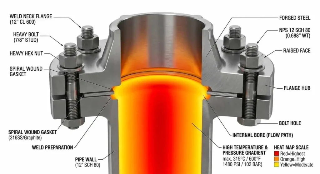
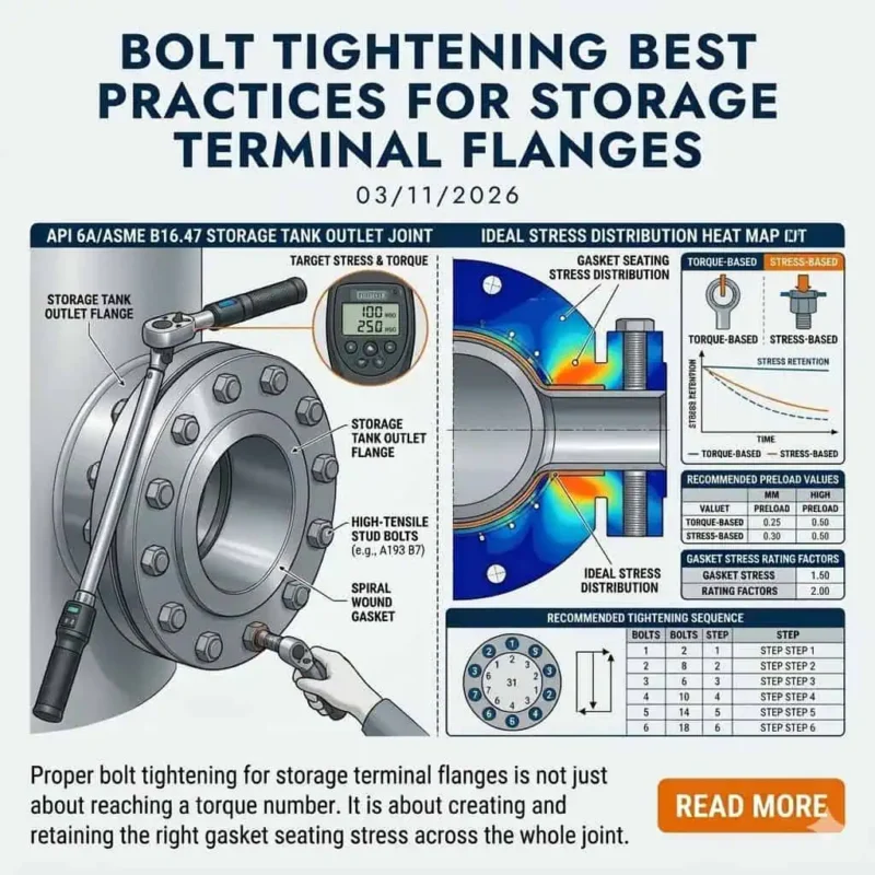
Refinery process units often operate under high pressure and elevated temperature with repeated start-up/shutdown cycles. These conditions load the flange joint through internal pressure, external piping loads, bolt relaxation, and differential thermal expansion. The selected flange must match the required pressure class and pressure-temperature rating for the specific material group, while also considering facing type, gasket seating stress, and bolting capability.
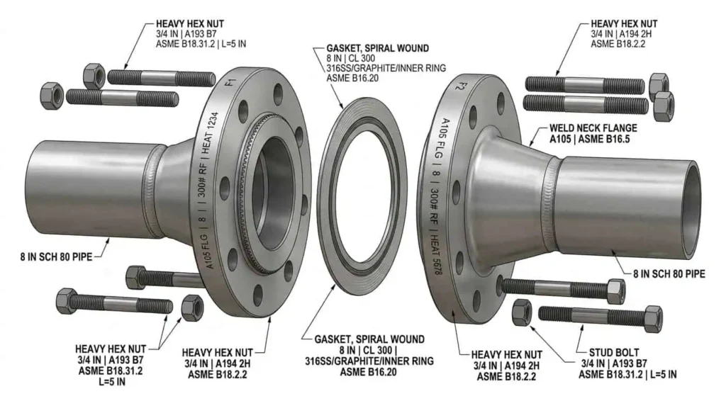
For severe service, weld neck flanges are commonly preferred because the tapered hub improves stress distribution and fatigue resistance. Reinforcement features, controlled flange thickness, and correct bolting design improve joint stability under cyclic service. Modern gasket technologies can improve leak tightness, but only when surface finish, compression, and flange flatness are controlled during installation.
| Flange Type / Design Feature | Application in High-Pressure Environments |
|---|---|
| Weld Neck / Butt Weld Connection | Preferred for high-pressure and high-temperature lines with thermal cycling and vibration due to better stress transition |
| Reinforcement Ribs / Heavier Section (where design permits) | Added stiffness and stability for large or heavily loaded joints under extreme conditions |
Field Example (HPHT Leak Recurrence): A Class 300 RF slip-on flange in cyclic hot-oil service developed repeat seepage after each turnaround. Root causes were uneven fillet weld geometry, gasket substitution without engineering review, and insufficient bolt load retention after thermal cycling. The permanent fix was a weld neck flange upgrade plus controlled gasket/bolting specification and tightening procedure.
Expert Insight:
A 30-year purchasing and field-support consultant notes, “Verify the pressure class and pressure-temperature rating from the applicable standard and the manufacturer’s documentation, then check the joint assembly details. Many failures happen because teams confirm flange size, but not the full joint design basis.”
Managing Corrosive Fluids and Sour Gas (NACE MR0175 Compliance)
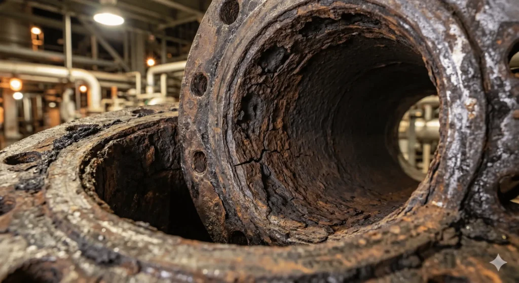
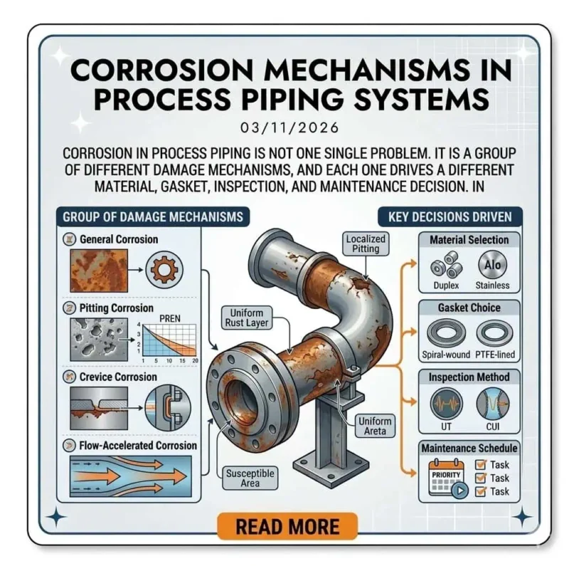
Corrosion is a leading cause of flange joint degradation in refineries, especially where stagnant pockets, wet H2S, chlorides, water condensation, or mixed metallurgy exist. Common mechanisms include crevice corrosion at the gasketed interface, galvanic corrosion between dissimilar metals, chloride-related attack in susceptible alloys, and environmental cracking in sour service. In sour environments, NACE MR0175 / ISO 15156 selection rules and limitations (including material grade, hardness, heat treatment condition, and service severity) must be considered as part of the engineering basis—not as a checkbox after purchase.
NACE compliance does not mean “all corrosion risk is eliminated.” It reduces cracking risk when materials are properly selected for the actual H2S-containing service conditions. Material verification, hardness control, traceability, and process-condition review remain essential. Duplex stainless steels, super duplex grades, and nickel alloys may be required in aggressive combinations of chlorides, temperature, and sour service, but the final choice depends on the full corrosion envelope and fabrication controls.
| Corrosion / Damage Mechanism | Engineering Concern at Flange Joints |
|---|---|
| Sulfide Stress Cracking (SSC) | Cracking risk in susceptible materials under tensile stress in H2S service; material hardness and condition are critical |
| Hydrogen Induced Cracking (HIC) | Internal cracking in susceptible steels; material quality and service chemistry strongly influence risk |
| Crevice Corrosion | Localized attack under gaskets or deposits where oxygen and chemistry differ from bulk fluid |
| High Chloride / Wet Cyclic Conditions | Can accelerate localized corrosion and damage passive films in unsuitable alloys |
| Flow Regime / Dead Leg Effects | Localized corrosion severity may increase at low-flow or deposit-prone locations (typical engineering range varies by chemistry and temperature) |
Field Example (Sour Water Overhead): A refinery experienced repeated flange leaks in a sour-water-related service after replacing bolts and gaskets during a shutdown. Investigation found missing material traceability for studs and inconsistent hardness records on replacement components. The corrective action included traceability enforcement, approved material lists, and PMI/hardness checks for critical joints before reassembly.
Expert Insight:
The consultant advises, “Request full material test certificates, heat treatment records where applicable, and NACE/ISO sour-service documentation for every critical flange package. Hidden material substitutions often create the most expensive failures.”
Meeting Strict Fugitive Emission Regulations and Leak Tightness
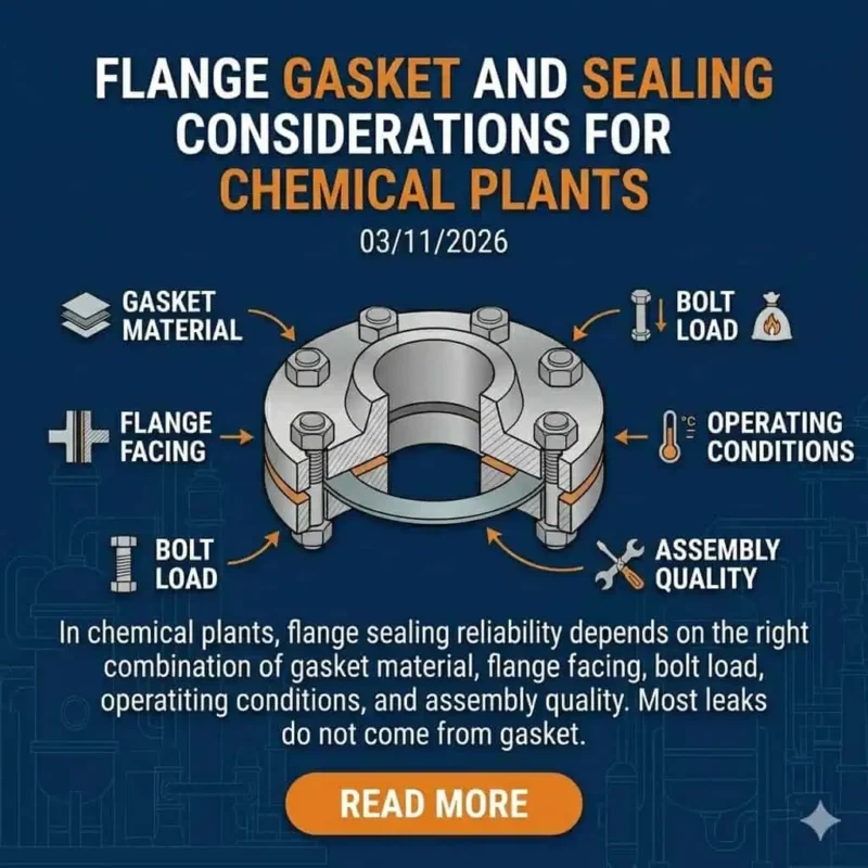
Modern refinery compliance programs increasingly focus on fugitive emission control and leak prevention. Flange leak tightness depends on correct flange facing selection, gasket type, surface condition, bolt preload, and installation practice. Raised face (RF) and ring-type joint (RTJ) flanges are widely used where tighter sealing performance is required, but performance depends on the entire assembly and maintenance discipline—not flange type alone.
One-piece body design in associated components can reduce leak paths, but flanged connections remain common and must be engineered for the expected service conditions, including upset temperature and pressure. In practical refinery work, many “flange failures” are actually assembly control failures: wrong gasket, damaged facing, reused fasteners beyond procedure, or uneven tightening patterns.
| Flange Facing Type | Description | Typical Use Case |
|---|---|---|
| Flat Face (FF) | Uses a full-face soft gasket; lower gasket stress and wider contact area | Low-pressure / lower-severity services and mating to flat-face equipment flanges where required |
| Raised Face (RF) | Concentrates gasket load on a raised sealing area for improved sealing efficiency | General refinery service across many moderate-to-high pressure applications (subject to rating and gasket compatibility) |
| Ring-Type Joint (RTJ) | Uses a metallic ring gasket with precision grooves for high-integrity sealing | Severe high-pressure / high-temperature service and critical leak-tight duties |
Field Example (Emission Compliance Gap): A unit flagged recurring low-level VOC leaks on RF joints after startup. Root cause review found non-approved gasket substitutions during maintenance and no facing inspection acceptance criteria documented. Updating the gasket control list, facing inspection standards, and bolt-tightening records reduced repeat leaks in the following operating cycle.
Expert Insight:
The consultant highlights, “Choose suppliers and contractors who document gasket compatibility, facing finish requirements, and pressure class suitability. Good paperwork upfront prevents leak investigations later.”
- Common challenges in refinery flange applications include:
- Leakage risk in HPHT or cyclic service when flange type, facing, gasket, and bolt load are not matched as a system
- Material degradation from corrosion, sour chemistry, deposits, and thermal excursions
- Installation and maintenance errors that reduce effective sealing stress
- Inspection difficulties caused by insulation, access constraints, and complex joint geometry
- Regulatory and internal reliability requirements for emissions control, traceability, and documentation
Specifying the Right Flange Type for Refinery Units
Weld Neck Flanges
Why They Are the Gold Standard for Critical Piping Systems
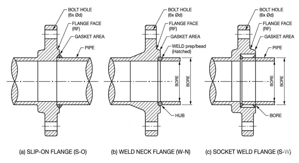
Weld neck flanges are frequently treated as the default choice for critical refinery piping because their hub geometry provides better stress distribution than many alternative types. In high-pressure lines, thermal cycling service, and vibration-prone locations, weld neck flanges generally deliver better fatigue performance and long-term joint reliability. They are especially valuable where leak consequence is high and repair access is poor.
These advantages do not remove the need for proper welding procedure qualification, fit-up control, NDE as required, and post-weld heat treatment (PWHT) when applicable. Installation cost is higher, but lifecycle cost is often lower when leak frequency, rework, and downtime are considered.
| Advantages | Limitations / Trade-Offs |
|---|---|
| Superior strength and better stress transition for pressure and thermal loads | Requires qualified welding and more installation time |
| Commonly preferred for critical high-pressure systems | Higher upfront fabrication and inspection cost |
| Better fatigue resistance in cyclic service when properly installed | Less convenient to modify than bolted-only temporary solutions |
| Strong long-term performance in refinery service | Quality depends on welding execution and joint alignment |
Blind Flanges
Best Practices for Equipment Isolation and Safe Maintenance
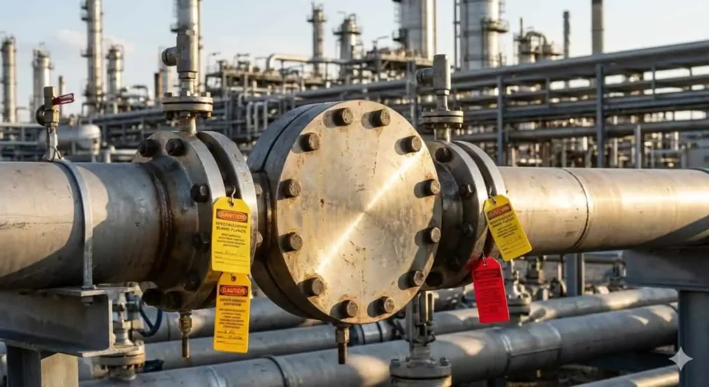
Blind flanges are essential for positive isolation, hydrotesting, future tie-ins, and maintenance planning in refinery piping systems. They close a pressure boundary and must be selected for the same design basis as the mating flange and service condition (including hydrotest condition, which may differ from operating condition). Blind flange thickness and bolting adequacy are critical engineering checks, especially at larger diameters and higher pressure classes.
- Blind flanges isolate piping sections for maintenance and line opening.
- They support pressure testing and commissioning activities.
- They provide flexibility for future tie-ins and phased project execution.
- Spectacle blinds offer clear operational status for periodic isolation duties.
- Isolation planning should include gasket type, bolt condition, and torque procedure—not just flange class.
Field Example (Hydrotest Delay): A turnaround hydrotest was delayed when a temporary blind flange package lacked traceable rating documentation and stud material records. Revalidation and replacement extended the outage window. A pre-shutdown blind flange register with ratings, sizes, and documentation requirements would have prevented the delay.
Slip-On and Socket Weld Flanges
Understanding Their Limitations and Risks in High-Stress Areas
Slip-on and socket weld flanges are widely used and can perform well in the right services, but they require stricter screening for critical refinery duty. Slip-on flanges may be less suitable for severe cyclic loading because fatigue performance depends heavily on weld quality and geometry. Socket weld designs can create crevice-prone regions and may be sensitive in corrosive or fouling services if not carefully specified and maintained.
These flange types are not “wrong” by default. The key is service classification: consequence of leak, cyclic loading, corrosion mechanism, inspection access, and maintenance practice. Where leak consequence is high or conditions are severe, engineers often specify more robust alternatives and tighter assembly controls.
| Type of flange | Leak / Reliability Risk Factors to Watch |
|---|---|
| Slip-on flange | Fatigue sensitivity in cyclic service, weld profile quality, alignment control |
| Socket weld flange | Crevice effects, weld execution quality, service suitability in corrosive/fouling conditions |
Selecting the Correct Flange Facing
Raised Face (RF) vs. Ring Type Joint (RTJ) for High-Pressure Services
Flange facing selection directly affects sealing performance and leakage risk. RF and RTJ are both common in refinery service, but they serve different sealing mechanisms and maintenance realities. RF joints offer flexibility across many services with a broad gasket selection range. RTJ joints deliver high-integrity sealing in severe conditions but require precise groove condition, compatible ring material, and stronger installation discipline.
When selecting a facing, engineers should evaluate: process severity, pressure-temperature envelope, gasket/ring availability, joint reusability expectations, surface finish requirements, bolt preload control, and maintenance competency. A technically superior facing can still underperform if the field team does not have matching installation and inspection controls.
| Flange Type | Characteristics | Performance Impact |
|---|---|---|
| Flat Face (FF) | Lower gasket seating stress; used where mating equipment requires FF | Limited suitability for high-pressure leak-tight duty |
| Raised Face (RF) | Common refinery facing with broad gasket options | Good leakage control when gasket, finish, and bolt load are correctly matched |
| Ring-Type Joint (RTJ) | Metallic ring gasket with precision groove sealing | High sealing integrity in severe high-pressure/high-temperature service |
Tip: Match flange type, facing, gasket technology, and bolting procedure to the actual refinery duty. Joint reliability comes from the full assembly design and field execution—not one component in isolation.
Metallurgy and Material Selection Strategy
Matching Material Grades to Process Conditions
Selecting flange material is a service-environment decision, not a price-only decision. Engineers should evaluate operating and upset temperature, pressure, process chemistry, corrosion mechanism, mechanical loading, fabrication route, and inspection requirements. Standards define baseline requirements, but the final material selection must reflect actual refinery process conditions and project specifications.
The table below summarizes the most important decision factors for metallurgy and material selection in refinery flange service:
| Factor | Why It Matters |
|---|---|
| Pressure & Temperature | Determine applicable pressure-temperature ratings, material suitability, and required flange class / wall strength basis |
| Corrosion Resistance | Controls resistance to general/localized corrosion and cracking mechanisms; sour/chloride service may require stricter material limits |
| Mechanical Strength & Toughness | Affects load capacity, brittleness risk, and performance in low-temperature or dynamic conditions |
| Weldability & Fabrication | Influences heat treatment, weld procedure qualification, repairability, and field execution risk |
| Traceability & QA Requirements | Critical for verifying material grade, heat number, compliance, and fit-for-service documentation |
Common flange material families used in refinery-related applications include:
- Carbon Steel (e.g., ASTM A105, A350 LF2): Cost-effective and strong for many services; temperature limits, toughness, and corrosion allowance must be checked against actual duty.
- Stainless Steel (e.g., 304/304L, 316/316L): Improved corrosion resistance; grade selection should reflect chlorides, temperature, and process contamination risks.
- Alloy Steel (e.g., ASTM A182 F11, F22): Common for elevated-temperature service where creep resistance and strength are required.
- Duplex / Super Duplex (e.g., F51, F53, F55): High strength and strong corrosion resistance in suitable environments, but fabrication and phase-balance control matter.
- Nickel Alloys (e.g., Alloy 625, C276): Used for severe corrosion and high-consequence applications where standard steels are not adequate.
Carbon Steel (e.g., ASTM A105) vs. Alloy and Stainless Steels
Carbon steel flanges such as ASTM A105 are widely used because they balance strength, availability, and cost. However, they are not universally suitable. Corrosion mechanism, temperature range, and toughness requirements can quickly eliminate carbon steel from consideration in refinery sub-services such as wet sour, chloride-contaminated, or low-temperature duty. For low-temperature service, engineers often evaluate impact-tested alternatives (for example, ASTM A350 LF2) based on project code and design conditions.
Stainless steels such as 304/304L and 316/316L provide improved corrosion resistance, but grade selection should be based on actual chemistry, temperature, and stress conditions—not generic “stainless is better” assumptions. 316/316L generally offer better chloride resistance than 304/304L, but aggressive chloride + temperature combinations can still require duplex or nickel alloys. Alloy steels such as ASTM A182 F11/F22 remain important for elevated-temperature service where mechanical performance and code compliance drive material choice.
Tip: Match the flange material to the full service envelope (normal, startup/shutdown, upset, cleaning, and hydrotest conditions). For sour or aggressive service, verify project requirements against NACE MR0175 / ISO 15156 and material qualification limits.
Material Verification and Quality Assurance
Material verification and manufacturing quality control are critical in refinery procurement because the cost of a material mix-up can far exceed the purchase price difference. Engineers and procurement teams should verify not only the flange body material but also bolting, gaskets, and any ring gaskets or accessories used in the final joint assembly.
The Crucial Role of Material Test Reports (MTRs) in Procurement
Material Test Reports (MTRs) provide traceable evidence of chemical composition and mechanical properties for the supplied material heat. In refinery projects, MTR review supports compliance with project specifications and applicable codes, and it helps verify that the flange can withstand pressure, temperature, and corrosion-related demands. For critical service, MTR review should be tied to heat numbers, markings, and receiving inspection records—not treated as a detached document check.
- MTRs confirm chemical and mechanical properties for the supplied material lot.
- They support compliance verification against project specs and code requirements.
- They improve traceability for future failure analysis, maintenance, and audit review.
Practical MTR Checkpoints: material grade, heat number, applicable standard/specification, heat treatment status (if applicable), tensile/yield values, hardness where required, impact test results where specified, and traceability to product markings.
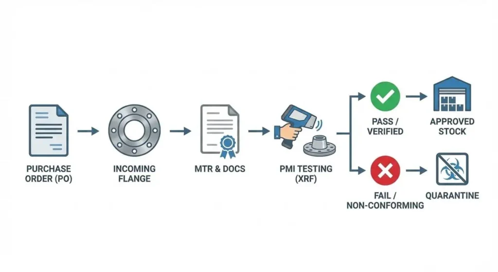
Mitigating Risks with PMI (Positive Material Identification) Testing
Positive Material Identification (PMI) testing helps prevent material mix-ups during receiving, fabrication, and maintenance. PMI verifies alloy chemistry and is especially valuable where visually similar materials can be confused (for example, carbon steel vs. low-alloy steel or different stainless grades). For refinery criticality-ranked joints, PMI should be applied through a documented sampling plan or 100% verification policy based on project risk requirements.
Teams should also understand PMI method limits. Handheld XRF is common and effective for many alloy checks, but method capability and test procedure must match the materials and elements being verified. When required by specification or risk level, supplemental methods and lab verification may be necessary.
- PMI confirms alloy identity and reduces substitution risk.
- It supports safe installation in high-consequence process units.
- PMI records improve traceability and failure investigation quality.
Note: Always request complete documentation and maintain traceability from PO to receiving inspection to installation. Clear product markings and linked records are essential for refinery reliability programs and future turnaround work.
Navigating Industry Standards and Specifications
Mastering ASME B16.5 and ASME B16.47 Dimension Codes
Industry standards provide the baseline framework for safe and interchangeable flange selection. ASME B16.5 and ASME B16.47 define core requirements such as dimensions, pressure-temperature ratings, materials, tolerances, marking, and testing. Engineers should use these standards as the dimensional/rating foundation and then apply project specifications, process requirements, and reliability controls on top of them.
- ASME B16.5 covers pipe flanges and flanged fittings for NPS 1/2 through NPS 24.
- ASME B16.47 covers large-diameter steel flanges for NPS 26 through NPS 60.
In refinery projects, the practical selection workflow should verify at least: pressure class, material group, facing type, dimensions/bolt pattern, mating flange compatibility, and marking requirements. Errors in bolt circle or facing configuration can cause expensive field delays even when the nominal size appears correct.
Tip: Confirm the flange standard, edition used by the project, pressure class, facing, and dimensional compatibility before releasing purchase orders or issuing field installation packages.
| Standard Type | Examples | Importance |
|---|---|---|
| National / Regional | GB/T, HG/T, JIS, DIN/EN (project-dependent) | Ensures compatibility with local requirements and project procurement norms |
| International / Global Project Baseline | ASME/ANSI, API, ASTM, ISO | Supports safety, interchangeability, and cross-border supply consistency |
Aligning with API Standards for Specialized Refinery Equipment
Refinery flange selection should not be isolated from the inspection and equipment standards used across the unit. API standards for piping inspection, pressure vessels, tanks, pumps, seals, and pressure-relief systems shape how joints are installed, inspected, repaired, and maintained during service life. This is especially important for procurement teams who may otherwise focus only on dimensional compliance.
For example, in-service piping inspection programs (such as API 570-based programs, where applicable) influence documentation, inspection access planning, and repair decisions around flange joints. Flange selection therefore affects not only startup performance but also long-term inspection and maintenance practicality.
| API Standard | Typical Relevance to Flange Selection / Maintenance |
|---|---|
| API 510 | Pressure vessel inspection interfaces, nozzle and vessel flange integrity considerations |
| API 570 | In-service piping inspection, repair, alteration, and rerating impacts on flange joints |
| API 650/653 | Tank systems and maintenance practices where flanged connections may be involved |
| API 610/674/675/676/682/683/685 | Pump, seal, and rotating equipment systems with leakage-critical flanged interfaces |
| API 660/661 | Heat exchanger systems with flanged connections requiring maintenance access and sealing reliability |
| API 520/521/2000 | Pressure relief / venting systems where leak-tightness and service suitability are critical |
| API 936 | Indirect relevance in refractory-lined equipment systems and shutdown planning coordination |
Proper flange selection must consider operating pressure, temperature, external loads, corrosion environment, inspection accessibility, and maintenance strategy. Noncompliance or poor specification alignment can cause leaks, recurrent failures, or regulatory findings.
Note: Verify that flange specifications align with both the project piping code basis (for example, ASME B31.3 for process piping projects) and the facility’s inspection/maintenance standards and procedures.
Vetting Your Flange Manufacturer and Supplier
Evaluating Quality Control Systems and ISO Certifications
Supplier quality systems directly affect refinery reliability. A flange that is dimensionally correct but poorly documented, incorrectly marked, or inconsistently heat-treated can create major risk in critical service. Manufacturers with structured quality control systems and auditable records are better equipped to prevent defects, maintain consistency, and support refinery documentation requirements.
ISO 9001:2015 certification is an important baseline for quality management, but buyers should still verify actual process controls: raw material traceability, in-process inspection points, final inspection criteria, calibration management, nonconformance handling, and documentation retention. For refinery use, the supplier’s ability to produce traceable records is often as important as the product itself.
- Quality control systems should:
- Identify defects before shipment
- Control dimensional and marking consistency
- Support compliance with project specifications and standards
- Reduce installation rework, leak risk, and downtime costs
Assessing Advanced Forging Capabilities and Traceability
Advanced forging and machining capability improves consistency, tolerance control, and supply reliability—especially for large-diameter or special-material flanges. However, capacity claims should be supported by evidence: equipment lists, inspection capability, documented procedures, sample reports, and traceability practices.
Traceability should cover the full chain from raw material to finished flange, including heat number linkage, machining records where applicable, inspection reports, and shipment documentation. Permanent markings should remain legible and consistent with documentation so receiving teams and maintenance personnel can verify material and rating in the field.
Quality control is non-negotiable in flange manufacturing. A trustworthy supplier should demonstrate controlled production, clear traceability, and relevant certification/documentation for the project scope—not only provide general marketing claims.
| Traceability Practice | Operational Benefit |
|---|---|
| Permanent markings (material, class, size, heat/ID where applicable) | Fast identification, receiving verification, and maintenance traceability |
| Complete documentation package (MTRs, inspection reports, certificates) | Auditability and reduced procurement/installation disputes |
| Third-party inspection reports for critical orders | Higher confidence for high-consequence refinery applications |
The Long-Term Value of Partnering with a Certified Expert Like SUNHY
For refinery and process-industry projects, long-term supplier value comes from consistent quality, traceable documentation, responsive technical support, and the ability to meet project-specific requirements—not only unit price. Suppliers that can support material verification, marking traceability, and inspection documentation reduce lifecycle risk for EPCs, procurement teams, and end users.
SUNHY’s positioning should be presented through verifiable capabilities: certified quality systems, documented traceability, machining/forging capacity, inspection controls, and the ability to provide complete documentation packages (such as EN 10204 3.1 material certificates where applicable). Framing supplier value around risk reduction and execution reliability aligns better with refinery buyer intent than generic marketing language.
Field failures often trace back to preventable causes: material mix-up, poor traceability, improper assembly, or specification mismatch. Supplier discipline in documentation and quality control is a primary defense against these failure pathways.
Choosing a supplier with proven process control and traceability can reduce rework, improve commissioning confidence, and support safer refinery operation over the long term.
Engineers and procurement managers should consistently match flange types to process conditions, verify material and documentation, and align selections with code and facility requirements. These steps significantly reduce leak and failure risk in refinery service.
- Accurate flange selection helps maintain piping integrity in hazardous and cyclic refinery services.
- Strict material verification and traceability reduce maintenance cost and failure investigation burden.
- Correct facing/gasket/bolting combinations improve leak-tight performance in HPHT and corrosive service.
Practical Daily Checklist (Refinery Flange Selection & Procurement): Confirm service conditions (normal/upset), applicable code/standard, flange type & class, facing, material grade, gasket compatibility, bolting grade, MTR/PMI requirements, marking/traceability, inspection plan, and installation procedure requirements before PO release or field issue.
Selecting certified suppliers and using this guide as a working checklist helps improve safety, cost control, and reliability across refinery operations.
FAQ
What is the most important factor when selecting a flange for refinery service?
The most important factor is service compatibility of the complete flange joint assembly. Engineers must match flange material, pressure class, facing, gasket, and bolting to the actual pressure, temperature, corrosion mechanism, and leak consequence. Reviewing only size and nominal class is not enough for refinery duty.
How can engineers verify the quality of a flange?
Use a layered verification approach: review MTRs, confirm markings/traceability, perform receiving inspection, and apply PMI testing for critical materials or high-consequence services. For sour or special materials, also verify applicable hardness/heat treatment records and project-specific compliance documents.
Which flange types are best for high-pressure refinery units?
| Flange Type / Facing | Typical Best Use Case |
|---|---|
| Weld Neck (often RF or RTJ as required) | Critical high-pressure lines, cyclic service, vibration-prone refinery piping |
| RTJ Facing (with compatible flange/joint design) | Severe high-pressure / high-temperature leak-tight service |
Weld neck flange designs and RTJ-facing joints are commonly selected for severe refinery service when pressure, temperature, leak consequence, and cyclic loading justify higher joint integrity requirements. Final selection must still follow project code and service-specific engineering review.
Why is traceability important in flange procurement?
Traceability links the installed flange to its verified material and inspection records. This allows engineers to confirm compliance during installation, maintenance, audits, and failure investigations. Without traceability, even a dimensionally correct flange may be unsafe to install in critical refinery service.
What certifications and documents should a refinery flange supplier provide?
- ISO 9001:2015 (quality management system baseline)
- Compliance to applicable flange standards (e.g., ASME B16.5 / B16.47 as specified)
- EN 10204 3.1 material certificates (where required by project/specification)
- MTRs, traceable markings, and inspection reports
- PMI / hardness / NACE-related documentation for critical sour-service orders, when specified
The exact certification/document package depends on project specification and service criticality, but refinery buyers should always require documents that prove material identity, standard compliance, and traceability.