The distinction between Class 150 and Class 300 flanges is a specification boundary that affects pressure–temperature limits, bolt pattern compatibility, gasket stress, and joint assembly requirements. In field work, wrong class selection rarely fails as “instant rupture”; it shows up as chronic leakage, flange rotation, gasket blowout, or bolt relaxation after thermal cycling—then escalates when transients (steam hammer, pump trips, blocked-in heating) occur.
This guide breaks down the technical differences in pressure handling, physical dimensions, and bolting patterns referenced by ASME B16.5 (Pipe Flanges and Flanged Fittings), then turns them into selection steps and inspection checks you can apply on drawings and in the field.
If you are sourcing stainless steel flanges, verify the material/heat traceability on the MTR (e.g., ASTM A182 F316/F316L for forged stainless flanges). Some manufacturers (including Sunhy) offer dual-certified 316/316L heats; the engineering value is traceability plus weld-sensitization resistance benefits of the low-carbon grade—provided the paperwork and PMI confirm it.
Class 150 vs Class 300: The Technical Core
Pressure-Temperature Ratings
The “Class” designation (150, 300, etc.) is a pressure–temperature rating designator (dimensionless). A common mistake is treating it as a direct psi limit. In reality, the allowable working pressure depends on temperature and material group. As temperature rises, allowable pressure drops because material strength and gasket stress retention degrade.
Below is a practical baseline comparison for carbon steel Group 1.1-type materials commonly referenced against ASME B16.5 charts (always verify against the controlling project spec/edition):
| Flange Class | Max Working Pressure @ -20 to 100°F (Typical Chart Value) | Max Working Pressure @ 600°F (Typical Chart Value) |
|---|---|---|
| Class 150 | ~275 psi | ~140 psi |
| Class 300 | ~720 psi | ~440 psi |
Engineering note: published charts often show small differences by edition, rounding convention, or material grouping. Use the design temperature/pressure from your line list and confirm the rating in the purchased ASME B16.5 tables. Do not ignore transient conditions.
Field example (selection error → leak event): A plant specified Class 150 on a 250 psig line because “150 flanges are fine up to ~275 psi at ambient.” The service was actually 400°F steam with frequent start/stop. After a few thermal cycles, leakage developed at several joints. Root cause was temperature derating plus bolt relaxation under cycling. Corrective action was upgrading to the appropriate class based on design temperature, then assembling per a controlled bolt-up procedure.
Use this quick selection sequence before you lock the class on the drawing:
- Step 1: Confirm design pressure and design temperature (not normal operating).
- Step 2: Confirm material grade and group (CS vs 316/316L changes ratings at temperature).
- Step 3: Check flange class rating at that temperature in ASME B16.5.
- Step 4: Verify gasket type and bolt material can maintain seating stress at temperature.
- Step 5: Confirm mating components (valves, instruments, equipment nozzles) are same class and standard.
Application Scenarios
The choice between these two classes dictates what the joint can tolerate in real service—especially thermal cycling, vibration, and pressure spikes. Treat the class as part of the entire pressure boundary, not a standalone component label.
| Flange Class | Industry Segment | Typical Service (Engineering Reality) |
|---|---|---|
| Class 150 | Light Industrial & Utilities | Water and low-temperature utilities, HVAC chilled water, fire protection, compressed air, low-pressure steam where temperature and transients are controlled. |
| Class 300 | Process & Heavy Industrial | Higher-pressure steam, hot oil, hydraulic/process lines with pressure spikes, refinery/petrochemical services where thermal shock and gasket blowout risk must be managed. |
Choosing the correct flange type is essential. Class 150 often meets utility duty efficiently, while Class 300 adds margin when the service includes elevated temperature, cycling, or higher consequence of leakage.
Sunhy’s 316/316L Advantage
Sunhy manufactures stainless flanges in 316/316L options. From an engineering perspective, the key is not branding—it is documented material control: MTR traceability (heat number), chemistry/mechanical compliance, and PMI verification. Low-carbon “L” grades reduce sensitization risk in welded systems, but stainless still has service limits (e.g., chloride environments and temperature can drive stress corrosion cracking). Specify material based on the fluid chemistry, temperature, and cleaning requirements, not only on class.
Engineering Deep Dive: The “Hardcore” Differences
To truly understand the difference between Class 150 and Class 300, look beyond the rating label and examine the geometry that controls joint stiffness: flange thickness, bolt circle, bolt hole size, and the gasket reaction zone. Many “mystery leaks” are not gasket defects—they are stiffness and assembly issues.
Visual Case Study: 4-Inch Weld Neck Flange
Let’s take a standard 4-inch (NPS 4) Weld Neck (WN) flange as a real-world example. The pipe bore is dictated by the pipe schedule, but the flange’s external geometry changes materially with class. This affects tool clearance, stud size, torque range, and the ability to maintain face flatness.
The technical drawing above highlights two dimensions that typically change with class:
- Flange Thickness: Higher class flanges carry more section modulus to resist rotation under bolt load and internal pressure.
- Bolt Circle (BCD): Higher class patterns usually move bolts outward and increase hole size to accommodate larger studs and higher assembly loads.
Field example (installation constraint → rework): On a retrofit skid, a Class 300 joint was specified correctly for pressure/temperature, but the designer missed tool swing clearance around the bolt circle. In the field, torque tooling could not access several studs due to nearby supports. The joint was assembled unevenly, then leaked during hot commissioning. Fix was mechanical: revise supports for access and reassemble with controlled passes.
The Data: 4″ Class 150 vs 300 Specs
Below is a practical dimensional breakdown for a 4-inch WN flange using commonly referenced ASME B16.5 dimension charts. Always verify dimensions against the flange type (WN vs SO) and the specific chart used for fabrication/inspection.
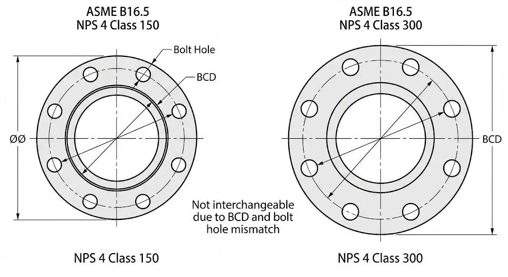
| Dimension (4″ NPS, WN) | Class 150 | Class 300 | The Practical Difference (What It Impacts) |
|---|---|---|---|
| Flange Thickness (typical chart “T”) | ~0.88″ (22.4 mm) | ~1.25″ (31.8 mm) | Higher stiffness helps keep gasket compression stable under cycling. |
| Bolt Quantity | 8 holes | 8 holes | Same count at NPS 4—do not assume compatibility. |
| Bolt Hole Diameter | ~0.75″ | ~0.88″ | Hole size drives stud selection and washer/nut fit-up. |
| Bolt Circle Diameter (BCD) | ~7.50″ (190.5 mm) | ~7.88″ (200.0 mm) | Different BCD means the flanges will not mate. |
Critical Engineering Note: Do not be fooled by the bolt count. At NPS 4, both classes commonly use 8 holes. However, the BCD and hole diameter differ, so you cannot bolt a Class 150 flange to a Class 300 flange without violating the standard pattern. Forcing fit-up damages studs, distorts faces, and makes gasket leakage more likely.
Field example (mis-mating → chronic leak): A maintenance team attempted to connect a Class 300 spool to a Class 150 nozzle by “oval-ing” holes on-site. The joint assembled, passed a cold leak check, then started weeping after a hot run. Root cause was face distortion and non-uniform gasket seating. Corrective action: replace with the correct class/nozzle adapter and restore the standard bolt pattern.
When Bolt Quantity Changes (e.g., 6-Inch)
At larger sizes, class differences often change bolt quantity as well as bolt size. This is not cosmetic; it is how the joint maintains uniform gasket stress at higher loads.
For example, on a 6-inch flange you commonly see:
- Class 150: 8 holes.
- Class 300: 12 holes.
This increased bolt density helps maintain gasket compression uniformity—especially important for hot services where gasket creep/relaxation and flange rotation are more severe.
Critical Design Detail: Flange Face Types
The difference between Class 150 vs Class 300 isn’t only thickness and drilling. The flange facing and gasket system must be aligned with the required seating stress and leakage risk. Face type is where “paper design” becomes “field performance.”
Raised Face (RF) vs. Ring Type Joint (RTJ)
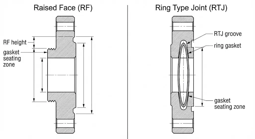
Both classes are commonly specified with a Raised Face (RF). A key detail many engineers miss: typical raised-face height is 1/16″ for Class 150 and Class 300 (higher classes often differ). RF is a gasket system decision more than a “strength” feature.
- Class 150 (RF): Widely used with soft gaskets (CNA, PTFE) in utility services. Leakage performance depends heavily on bolt-up quality and face condition.
- Class 300 (RF & RTJ): RF is common, but higher-risk services (hot hydrocarbons, higher cycling, higher consequence) may drive engineers to specify RTJ for metal-to-metal sealing performance—when the mating equipment and assembly controls support it.
Engineering Insight: RTJ is typically selected when you need higher seating stress and better blowout resistance than soft-gasket RF systems can reliably deliver. RTJ success depends on groove condition, ring material compatibility, and controlled bolt-up—not just on choosing Class 300.
Gasket & Bolting: The Hidden Variables
Selecting the correct class is only half the work. Most leakage events I’ve investigated trace back to gasket choice, bolt condition/lubrication, and tightening method. Industry guidance such as ASME PCC-1 exists for a reason: uncontrolled bolt-up creates non-uniform gasket stress and early relaxation.
| Component | Class 150 System (Typical) | Class 300 System (Typical) |
|---|---|---|
| Typical Gasket | CNA or PTFE for clean utilities; SWG may be used if faces/bolting support it | Spiral Wound Gasket (SWG) with centering ring; inner ring where required by bore/face conditions |
| Bolt Material | ASTM A193 B7 (common for CS systems) | ASTM A193 B7 or higher-temp grades where required; verify nut grade and temperature limits |
| Assembly Control | Moderate: still needs star pattern passes | High: calibrated torque control, multiple passes, lubricant consistency, and re-torque policy when applicable |
Why Gasket Selection Matters
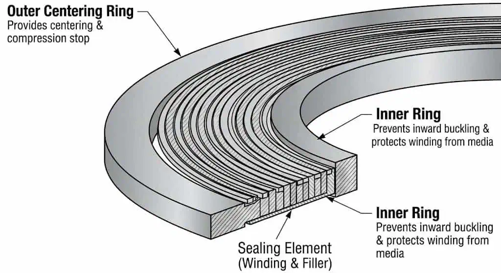
In a Class 300 system, pressure and thermal movement work the gasket harder. A common failure mode is gasket “blowout” or extrusion when the gasket system cannot maintain seating stress. Spiral wound gaskets help because the winding behaves like a spring, but only if the joint is assembled correctly and the gasket style (with outer/inner rings where needed) matches the flange bore and service.
Field example (wrong gasket + bolt-up → blowout): A Class 300 hot oil line used a soft gasket intended for low-stress utility duty. The joint sealed cold, then leaked after heat-up and vibration. Root cause was creep/relaxation plus insufficient seating stress retention. Fix: specify a gasket system appropriate for the service and reassemble using controlled tightening passes with verified stud condition and lubrication.
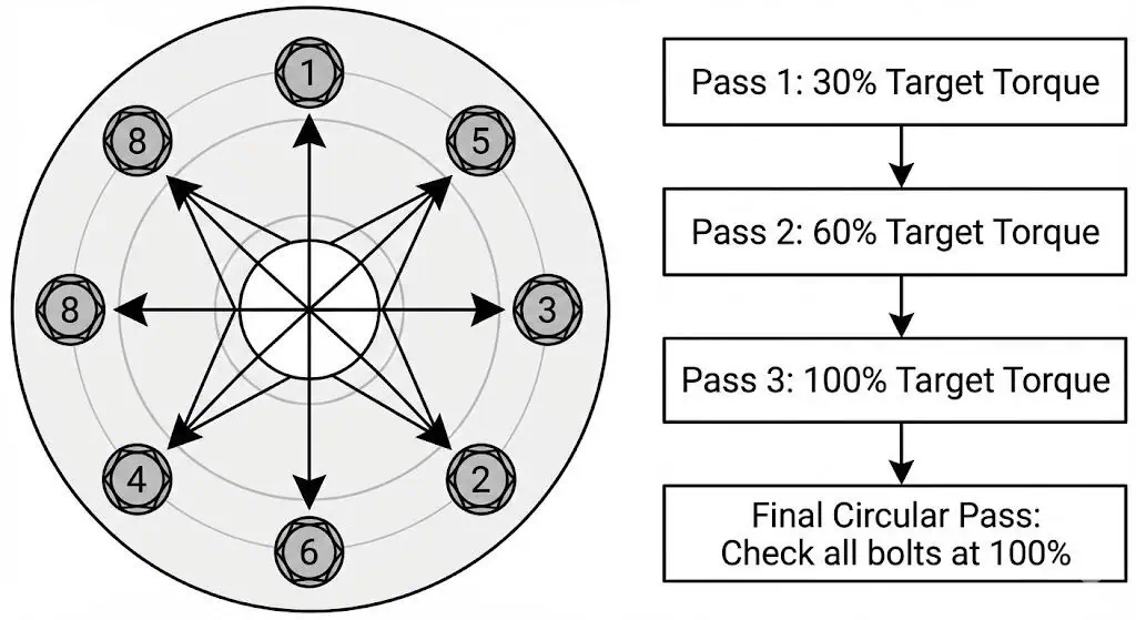
Minimum practical bolt-up checklist (works for both classes, becomes mandatory discipline at Class 300):
- Clean and inspect flange faces; reject deep dents/gouges in the sealing band.
- Verify gasket type, size, and orientation; ensure centering ring sits correctly.
- Confirm studs/nuts are correct grade, undamaged threads, and consistent lubrication.
- Tighten in a star/cross pattern using staged passes (e.g., 30% → 60% → 100%), then a final circular pass to check nut rotation.
- Document final torque and joint identification for critical services.
Verification: Hydrostatic Testing Standards
Hydrotest language is frequently misunderstood. ASME B16.5 does not require individual flanges to be pressure tested as standalone products; pressure testing requirements apply to flanged fittings and to the assembled system under the governing piping code and project procedure. Treat the flange class as a rating framework—not a substitute for a code-compliant test plan.
Practical engineering takeaways for commissioning:
- Differentiate: product/fitting tests vs system hydrotest under ASME B31.x or project standard.
- Never “prove” a class by over-pressurizing beyond the test procedure; over-test can permanently yield the flange or overload fasteners.
- Leak checks after heat-up are critical for hot services because gasket stress changes with temperature and relaxation.
Field example (over-test → permanent distortion): A utility line built with Class 150 flanges was hydrotested using a pressure intended for a higher-class system. The flanges did not burst, but several joints developed persistent seepage later. Post-mortem showed face rotation/bolt stretch beyond elastic range. The cost was not “catastrophic failure”—it was repeated outages and rework.
When to Use Class 150 Flanges
Optimized for Low-Pressure Utility
Class 150 flanges are widely used where the duty is utility-focused and temperature/transients are controlled. They are lighter, easier to handle, and typically reduce installed cost—when they are truly within the design envelope.
Best Fit Applications:
- Water Distribution: Municipal water lines and wastewater treatment.
- HVAC: Chilled water and low-pressure heating loops.
- Food & Beverage: Moderate pressure services where hygiene/material compatibility matters more than class margin.
- Fire Suppression: Standard sprinkler feed lines (per project and authority requirements).
Procurement/QA tip: For Class 150 utility work, most “leaks” still come from face damage, wrong gasket size, and uneven bolt-up. Add a simple incoming check: class stamp, MTR heat number, face condition, hole pattern match, and gasket fit verification.
Industry Deployment
Class 150 is often used in chemical and pharmaceutical facilities not because the pressure is low, but because stainless material compatibility, surface condition, and documentation control drive the spec. In those cases, selection discipline shifts from “pressure margin” to “materials + cleanliness + traceability + repeatable assembly.”
When to Upgrade to Class 300
Handling High Pressure & Thermal Shock
Moving to Class 300 is necessary when the design envelope includes higher pressure and/or temperature, or when the service includes cycling and higher leak consequence. This class increases stiffness and typically requires more disciplined assembly controls.
Why upgrade? A “pressure-only” check at ambient temperature can be misleading. If the service includes elevated temperature, the allowable working pressure can drop sharply. Your decision should be based on design temperature and material rating at that temperature, not on ambient values.
Critical Service Examples
- Main Steam Lines: hot steam distribution with cycling and vibration.
- Hydraulics: higher-pressure fluid power systems with dynamic spikes.
- Refining/Process: hydrocarbon services where leakage consequence is high.
According to the Class 300 pressure tables, Class 300 provides additional margin, but only when the rest of the system (valves, gaskets, studs, and assembly method) is controlled to the same rating discipline.
System Consistency: Valves & Gaskets
Matching the “Weakest Link”
A piping system is only as strong as its lowest-rated component. Even if a Class 300 flange is correctly selected, pairing it with a lower-rated valve end, a mismatched standard (ASME vs EN drilling), or an incompatible gasket system creates a reliability trap.
Field example (standard mismatch): A site received a valve drilled to an EN pattern while the spool was ASME B16.5. On paper both were “similar size,” but the bolt circle did not match. The only safe correction was to replace the valve ends or use the correct standard adapter—never modify the pressure boundary by slotting holes.
Rule of Thumb: Flanges, valves, and gaskets must share the same pressure class and compatible drilling standard at the joint. Do not mix classes or standards in a single flanged joint.
Summary: Making the Right Choice
Choosing between Class 150 and Class 300 comes down to matching your design pressure + design temperature + material group to the rating tables, then confirming bolt pattern, facing, gasket, and assembly controls are aligned.
| Feature | Class 150 | Class 300 |
|---|---|---|
| Typical Ambient Rating (CS charts) | ~275 psi | ~720 psi |
| Geometry | Lighter thickness and smaller drilling pattern | Heavier section, larger drilling pattern, higher stiffness |
| Joint Sensitivity | Can still leak if faces/bolt-up are poor | More tolerant in stiffness, but demands better gasket/bolt-up control |
| Best Use | Utilities and controlled-duty services | Higher pressure/temperature, cycling, higher consequence services |
If you are buying flanges for either class, ask for MTR traceability, confirm markings (class, material, heat), verify drilling pattern, and control bolt-up quality. In practice, good assembly discipline prevents more leaks than “buying a higher class”.
FAQ
Can I bolt a Class 150 flange to a Class 300 flange?
No. Even when bolt count looks similar (e.g., NPS 4), the bolt circle diameter and hole size differ, so the patterns will not align. Modifying holes or forcing fit-up violates standard drilling and increases leakage risk due to face distortion and uneven gasket stress.
Is Class 300 always better than Class 150?
No. Class 300 adds stiffness and higher rating capacity, but it costs more, weighs more, and often requires higher assembly control (stud size, torque range, access). If your design envelope is truly low-pressure/low-temperature and controlled, Class 150 is the correct engineering choice.
How do I visually tell them apart?
Check the stamp on the flange rim (e.g., “150” or “300”), then confirm the drilling pattern. Visually, Class 300 flanges are typically thicker and have a larger bolt circle/holes for the same NPS. For critical work, do not rely on “looks”—verify BCD and hole diameter against a chart before fit-up.
Does “Class 150” mean the flange is limited to 150 psi?
No. “Class” is a pressure–temperature rating designation. At ambient temperature, many carbon steel charts show Class 150 allowable pressure well above 150 psi, but at higher temperature the allowable pressure drops. Always design to the temperature-dependent rating and the project code.
What gasket is typically used for Class 300 raised face joints?
Spiral wound gaskets are common for Class 300 RF joints in hot/cycling services because they can maintain sealing stress better under relaxation—provided the joint is assembled with controlled passes and the gasket style (rings) matches flange bore/face conditions. Gasket choice must be compatible with the fluid chemistry and temperature.