
If your piping job crosses regions, the quickest way to lose time and money is ordering “the right size” flange to the wrong standard. JIS vs ANSI vs DIN flanges are not directly interchangeable: bolt circle, bolt size, facing details, and rating systems are different. The practical goal is simple—match the project standard on the drawing, then confirm the flange matches the mating part in three checks: dimensions, facing, and pressure–temperature rating.
- ASME B16.5 (ANSI/ASME) standardizes dimensions, facing, marking, and pressure–temperature rating tables so parts built to the same class and material group fit without rework.
- EN 1092-1 (DIN/EN) uses metric DN/PN designations and defines flange types/facings widely used across Europe and many EPC specs.
- JIS B 2220 defines steel pipe flanges by “A” nominal size and “K” nominal pressure series common in Japan and much of Asia-Pacific supply chains.
Sunhy supplies stainless steel flanges for demanding environments. For engineering teams, the useful question is not the brand—it’s whether the flange is built and documented to the same standard, heat traceability, and inspection scope your project requires.
JIS vs ANSI vs DIN: Key Differences
Understanding the key differences between jis vs ansi vs din flanges helps you select parts that assemble cleanly and seal the first time. Each standard defines a complete “fit-and-seal package”: dimensions (OD, thickness, bolt circle), facing details, marking, materials, and rating rules. The safest workflow is: confirm the governing standard in the piping class/spec, then verify the mating flange drawing before purchasing.
Design Features Compared
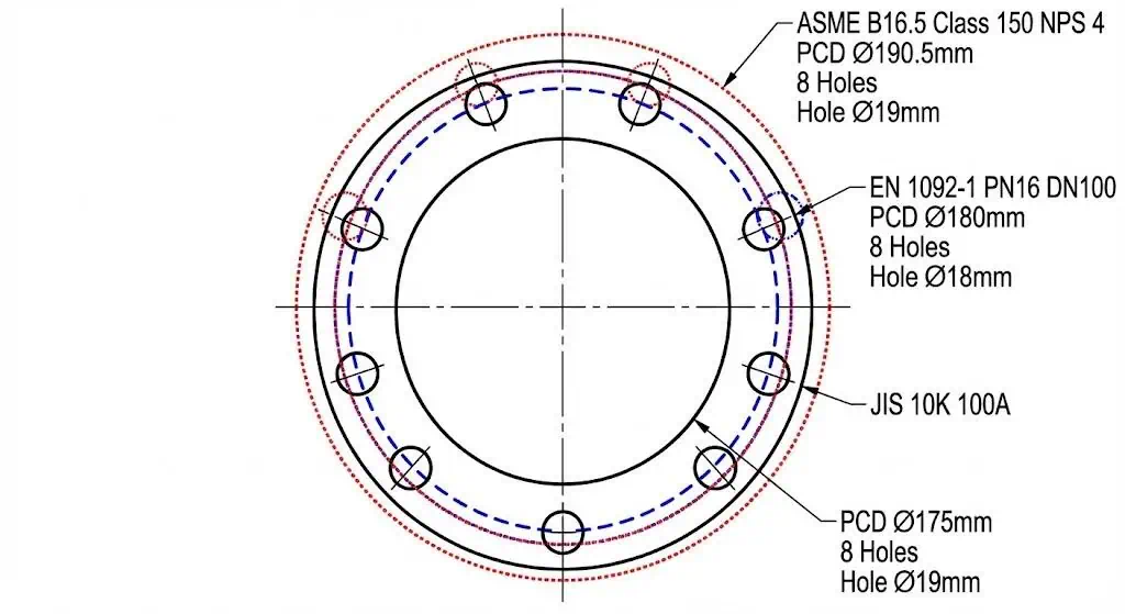
In the field, people summarize it as “ANSI is bigger, JIS is compact, DIN is metric.” The more accurate view is: (1) ASME/ANSI is typically specified in NPS and class designations; (2) DIN/EN is DN/PN and flange “types”; (3) JIS is nominal size “A” and “K” series. The differences show up first at the bolt circle and bolt size—exactly where rework happens when standards get mixed.
| Flange Type | Nominal Size | Bolt Holes | Bolt Circle (mm) | Pressure Rating |
|---|---|---|---|---|
| JIS 10K | 100A (≈4”) | 8 | 175 | 10K (nominal) |
| ANSI Class 150 | 4” | 8 | 190 | Class 150 |
| DIN PN16 | DN100 | 8 | 180 | PN16 (nominal) |
- ANSI/ASME flanges follow dimensional rules in ASME B16.5 (and large diameter in ASME B16.47), so bolt patterns and facing details are predictable within each class/size.
- JIS flange designs often come with smaller bolt circles for the “same” line size, which matters when you have limited wrench swing or tight skid layouts.
- DIN/EN flanges use metric DN and defined flange types; the project spec normally calls out both PN and the flange type/facing form.
Tip: If you only do one pre-install check, measure the bolt circle (PCD) and confirm bolt size. “DN100” and “4 inch” describe the line, not the flange drilling.
Field example (misalignment): A DN100 PN16 valve arrived on site and the crew tried to bolt it to an ASME Class 150 spool because the line tag said “100/4.” Holes were close but not true; bolts went in at an angle, gasket crushed unevenly, and the joint seeped during hydrotest. The fix was not “more torque”—it was a proper transition piece with the correct drilling and facing on each side.
Pressure Ratings Overview
JIS, ANSI, and DIN use different rating languages. Treat these as systems, not unit conversions: ASME “Class” is not a direct psi value; DIN “PN” is a nominal series tied to reference conditions; JIS “K” is a nominal series historically based on kgf/cm². What actually matters for safety is the pressure–temperature rating for the material at the design temperature, plus the gasket/bolting limits.
| Standard | Pressure Ratings | Description |
|---|---|---|
| ANSI | 150, 300, 600, 900 | Class designations with pressure–temperature tables by material group (do not read “150” as “150 psi”). |
| DIN | PN10, PN16, PN25 | Nominal pressure series; allowable pressure reduces as temperature rises and depends on material group. |
| JIS | 10K, 16K, 20K | Nominal “K” series commonly used in Japan/Asia; confirm rating tables and temperature limits. |

- JIS uses “K” series commonly associated with kgf/cm² nominal pressure—treat it as a rating family, then verify allowable pressure at your design temperature.
- ANSI/ASME uses “Class” with pressure–temperature tables tied to material groups in the standard.
- DIN/EN uses “PN” nominal series; project specs usually define PN + flange type + material group.
Engineering check: If your design temperature is elevated (steam, hot oil, thermal cycling), do not “convert” PN/K/Class. Pull the rating table for the exact material and temperature and document it in the line list.
Dimensional Standards
Dimensions are where mixing standards fails first. For a given line size, standards can differ on flange outside diameter, thickness, raised-face diameter, bolt circle, and bolt size. Even when the hole count matches, a few millimeters of bolt circle difference forces bolts to “bend into place,” which reduces preload consistency and increases leak risk.
| Feature | JIS Flanges | ANSI Flanges |
|---|---|---|
| Bolt Hole Patterns | Defined per JIS series and nominal size | Defined per ASME class and NPS |
| Flange Face | Facing details vary by JIS type/class | RF/FF/RTJ options with defined facing geometry |
DIN and JIS are both metric in many dimensions, but they are not the same drilling or facing rules. ANSI/ASME uses inch-based bolt sizing even when dimensions are provided in metric units. Before ordering, confirm the mating standard on valves, pumps, heat exchanger nozzles, and skid interfaces—the “line size” alone is not enough.
Material Specifications
JIS, ANSI, and DIN standards point to different material grades for flanges, which affects strength, weldability, and corrosion behavior. The safest method is to specify by the project’s material standard (ASTM/ASME or EN/JIS) and require traceable mill test reports for each heat.
- JIS commonly uses Japanese grades such as SS400 and SUS304 (and equivalent stainless families by JIS designation).
- ANSI/ASME commonly specifies ASTM/ASME grades such as A105 (carbon steel) and A182 F304/F316 (stainless/alloy).
- DIN/EN commonly uses EN material numbers such as 1.4301 (≈304) and 1.4404 (≈316L), depending on service and welding requirements.
| Material Type | Specification | Application Description |
|---|---|---|
| Carbon Steel | ASTM A105 | Common for pressure systems at ambient and higher temperatures; confirm impact toughness when temperature is low. |
| Stainless Steel | ASTM A182 | Used for corrosive/high-temperature service; grade selection depends on chloride level, temperature, and welding practice. |
| Low-Temperature Carbon Steel | ASTM A350 | Selected when the minimum design metal temperature requires verified toughness. |
| Alloy Steel | ASTM A182 F11, F22 | Common in high-temperature service (power/refining); welding procedure control matters for long-term integrity. |
Note: Sunhy manufactures flanges from dual-certified 316/316L stainless steel forgings. From an engineering standpoint, “316/316L” matters when welding is involved: the L-grade reduces sensitization risk in many heat-affected zones, but you still need the correct filler metal, heat input control, and post-weld cleaning for chloride service.
Field example (material selection error): A seawater utility line used 304 stainless flanges because they were “available and stainless.” After months of warm service, crevice corrosion initiated under the gasket seating area and the joint began to seep. The corrective action was upgrading to a more suitable material (often 316/316L in similar service, depending on chloride level and temperature), improving gasket selection, and enforcing washdown/cleaning practice.
Typical Applications
Regional usage is real, but project specification controls the job. You typically see ASME/ANSI in the Americas and many oil & gas EPC specs, JIS across Japanese/Asia-Pacific equipment ecosystems, and DIN/EN throughout Europe and regions that adopt EN flange types.
- ANSI/ASME flanges are common in oil & gas, chemical, and power generation projects that follow ASME piping classes.
- JIS flanges are common in Japanese industrial plants, shipbuilding, and many Asia-Pacific supply chains tied to Japanese equipment standards.
- DIN/EN flanges are common in European chemical, water treatment, and manufacturing plants where EN 1092-1 types are specified.
Practical rule: match the flange standard to the equipment nozzle standard and the piping class. If you must transition, design it as a dedicated transition spool—don’t “make it fit” in the field.
JIS Flange, ANSI Flange, and DIN Flange Overviews
JIS Standard and Usage
JIS flange follows Japanese Industrial Standards and is widely used in Asia.
On many projects, the governing document is JIS B 2220 for steel pipe flanges, defined by nominal size “A” and nominal pressure series such as 5K, 10K, 16K, and higher series depending on service. JIS parts are often physically compact for a given line size, which helps in tight skids, but it also increases the chance of mismatch when someone assumes “4 inch equals DN100 equals 100A.”
- JIS flange series are specified by K rating (commonly 5K/10K/16K/20K and higher series depending on the standard/type).
- Common in marine, chemical, utilities, and industrial piping tied to Japanese equipment standards.
- Metric dimensions are typical; confirm drilling and bolt sizes before mixing with EN systems.
Tip: When the datasheet says “100A,” verify the bolt circle and bolt size from the JIS table. Do not order by “DN100” alone unless the standard is stated.
ANSI Flange in the Americas
ANSI flange (commonly called ASME/ANSI flange on job sites) is the dominant system in North and South America for industrial piping.
The controlling standard for many projects is ASME B16.5 (NPS 1/2 through NPS 24) and ASME B16.47 for large diameter steel flanges. These standards define dimensions, facing, marking, and pressure–temperature rating tables. “Class 150/300/600…” is a designation system, not a pressure unit.
- ANSI/ASME flange class designations commonly include 150, 300, 400, 600, 900, 1500, and 2500 (scope depends on the standard and size range).
- Common in refineries, pipelines, power plants, and chemical facilities built to ASME piping classes.
- Inch-based bolt sizing is typical; always confirm bolt diameter/length and gasket type with the flange facing.
Note: A “Class 150” flange is not “150 psi.” Always use the pressure–temperature rating tables for the exact material group and design temperature.
DIN Flange in Europe
DIN flange in modern specifications is usually an EN 1092-1 steel flange with PN designation.
You find these flanges in water treatment, chemical processing, district energy, and general industry across Europe and many regions that adopt EN flange types. EN 1092-1 defines flange types, dimensions, facing forms, and PN series; allowable pressure depends on material group and temperature.
- DIN/EN PN series commonly includes PN6, PN10, PN16, PN25, PN40, PN63, PN100, and higher where specified.
- Common in European industrial and municipal systems where DN/PN is used throughout the piping class.
- Project specs often define flange type + facing + gasket standard (for example EN 1514 gasket series) to avoid mismatch.
Tip: If a purchase request says “DIN PN16,” ask which EN 1092-1 type and facing is required. That single line item prevents most site-fit surprises.
Sunhy’s Global Flange Solutions
For global projects, the practical value is consistent manufacturing control across standards: forged vs plate, machining tolerances, NDT scope, heat traceability, and documentation. Sunhy manufactures flanges to JIS, ASME/ANSI, and EN/DIN requirements, including large diameter and higher-pressure designs when the governing standard calls for them. If your interface is non-standard, treat it as an engineered transition and submit drawings so the drilling/facing are correct by design.
| Flange Standard | Specifications |
|---|---|
| JIS | JIS B2220 5K, 10K, 16K, 20K, 30K, 40K (confirm series and type on the datasheet) |
| ANSI | ASME B16.5 / ASME B16.47 Class series (RF, FF, RTJ per project spec) |
| DIN | EN 1092-1 PN series (type/facing defined by the piping class) |
| Large Diameter | ASME B16.47 (NPS 26–60) for large diameter steel flanges |
| High Pressure | API 6A 6B & 6BX for wellhead/subsea interfaces when specified |
| Custom Flanges | Custom / Non-Standard: submit drawings and specify mating standard, facing, and gasket type |
If you want reliability, specify the standard, facing, gasket, bolting grade, and documentation package—then inspect to that list at receiving.
Dimensional Comparison of Flanges
Bolt Patterns and Sizes
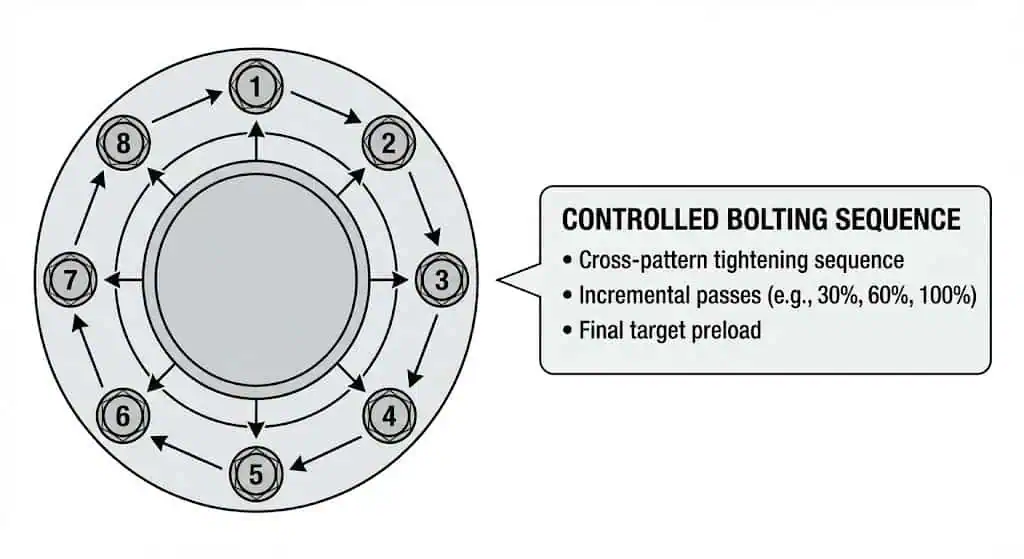
Bolt patterns and bolt sizing differ among JIS, ANSI/ASME, and DIN/EN flanges. This affects installation time, bolt procurement, torque procedure, and whether the joint achieves uniform preload.
You notice that ASME flanges use bolt patterns tied to class and NPS; DIN/EN uses DN/PN plus flange types; JIS uses nominal size “A” plus K series. These differences mean you should verify bolt alignment before connecting flanges from different standards. A quick site method is: measure bolt circle (PCD), count holes, measure hole diameter, then confirm bolt size and length on the flange drawing.
| Feature | ANSI Flanges | DIN Flanges | JIS Flanges |
|---|---|---|---|
| Dimensions | Defined by class + NPS | Defined by type + DN/PN | Defined by nominal size A + K series |
| Pressure Ratings | Class designation with P–T tables | PN nominal series with temperature/material limits | K nominal series with temperature/material limits |
| Market Focus | Americas + ASME-driven EPC specs | Europe + EN-driven EPC specs | Japan/Asia-Pacific supply chains |
Tip: If bolts “almost” fit, stop. Forced alignment is a preload problem waiting to become a leak.
Face Types and Thickness
Face types and thickness affect gasket seating stress and joint stiffness. This is where joints pass a hydrotest and then start weeping after thermal cycling—because the gasket was never loaded evenly or the facing mismatch concentrated stress.
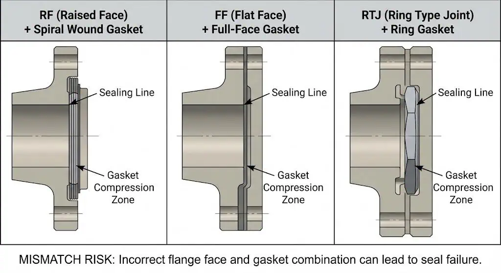
ASME flanges commonly use raised face (RF), flat face (FF), and ring-type joint (RTJ). DIN/EN provides multiple flange facing forms defined by type. JIS facing forms depend on the JIS series and flange type. When you select a flange, match the facing to the gasket and the mating flange; “RF to FF” combinations are not automatically acceptable without an engineered gasket solution.
- ANSI/ASME: RF, FF, RTJ options; thickness varies by class.
- DIN/EN: facing forms defined by flange type; thickness varies by PN and type.
- JIS: facing depends on the JIS series/type; confirm gasket selection accordingly.
Field example (sealing failure): A spiral-wound gasket intended for RF was installed against a mismatched facing. The joint held during initial fill but seeped after the first heat-up. The corrective action was to match facing and gasket type, then reassemble with a controlled bolting procedure rather than “tighten until it stops.”
Size Ranges
Size ranges depend on the governing standard. In ASME, B16.5 covers common flange sizes up to NPS 24; large diameter flanges are handled in separate standards. In EN, the range depends on the PN series and flange type. In JIS, the nominal “A” size range and K series depend on the specific JIS standard and edition.
As a procurement step, always attach the governing standard page and the flange drawing to the RFQ. That single attachment prevents “DN vs NPS” interpretation errors and reduces receiving inspection disputes.
| Standard | Size Range | Description |
|---|---|---|
| JIS | Depends on JIS edition/series | Nominal size “A” with K series; verify exact scope from the JIS document used on your project. |
| ANSI | NPS 1/2 to NPS 24 (B16.5) | Common ASME flange range; large diameter is covered by separate standards. |
| DIN | Depends on PN/type | EN 1092-1 PN series; allowable pressure depends on temperature and material group. |
Review flange dimensions, facing, and pressure–temperature ratings together. Checking only one of the three is how mismatches slip through.
Choosing the right standard and size range is mostly about interface control: identify where your piping meets equipment, then lock the standard at that boundary.
Pressure Ratings and Classes in JIS, ANSI, DIN
JIS Pressure Classes
JIS pressure classes use “K” series designations in JIS flange specifications.
Common series include 5K, 10K, 16K, and higher series depending on application. Treat “K” as a rating family and verify allowable pressure at design temperature for your specific flange type/material. On jobs with steam or hot oil, the temperature effect is often what drives the selection—not the room-temperature nominal series.
| Standard | Pressure Class Designations |
|---|---|
| JIS | 5K, 10K, 16K, 20K, 30K, 40K (series depends on the JIS document used) |
Tip: When “10K” is specified, confirm whether the project expects JIS B 2220 steel pipe flanges or another JIS flange standard—then verify drilling and facing before procurement.
ANSI Pressure Classes
ANSI/ASME pressure classes use a “Class” system (e.g., 150, 300, 600) defined in the standard’s pressure–temperature tables.
You see class designations such as 150, 300, 600, 900, 1500, and 2500. The key rule is that class rating depends on material group and temperature; the same class designation has different allowable pressures for different materials and drops as temperature rises.
- ANSI/ASME flanges are designed around pressure–temperature tables, with ASME B16.5 covering the common size range and classes used in most process piping.
- Selection in high-pressure or cyclic service should include gasket stress requirements and a controlled bolting plan, not “tighten by feel.”
| Standard | Pressure Class Designations |
|---|---|
| ANSI | 150, 300, 400, 600, 900, 1500, 2500 |
Note: Always document the pressure–temperature rating using the exact flange material and the design temperature. That record is what protects you during MOC and audits.
DIN Pressure Classes
DIN/EN pressure classes use a “PN” system (“nominal pressure”) expressed as a series designation.
Common PN series include PN10, PN16, PN25, and PN40, with higher series available where specified. In practice, allowable pressure depends on temperature and material group; PN is not a guarantee at elevated temperature without checking the rating rules.
| Pressure Class | Applications |
|---|---|
| DIN/EN PN6 | Low-pressure water/utility systems where specified |
| DIN/EN PN10 | Water treatment, general utilities, low-pressure process service |
| DIN/EN PN16 | Common industrial water/process service; often the default in many plants |
| DIN/EN PN25 | Higher-pressure utilities and process applications |
| DIN/EN PN40 | Higher-pressure process service where specified |
| Standard | Pressure Class Designations |
|---|---|
| DIN | PN6, PN10, PN16, PN25, PN40, PN63, PN100 (and higher where specified) |
Engineering check: For temperatures above the reference range used for PN, confirm the p/T rating rule for your material group and record it on the line list.
Material and Quality Standards
Common Materials Used
You see stainless steel, carbon steel, and nickel alloys used across JIS, ASME/ANSI, and DIN/EN systems. The “right” material is dictated by corrosion mechanism, temperature, welding requirements, and inspection scope—not simply by what a vendor typically stocks.
| Material Type | Corrosion Resistance Description |
|---|---|
| Stainless Steel | Good general corrosion resistance; grade selection depends on chloride level, temperature, and crevice conditions (gasket seating areas are common initiation points). |
| Nickel Alloys | Selected for severe corrosion or high temperature; typically justified by a corrosion study and lifecycle cost, not by purchase price. |
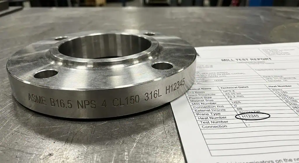
For quality control, require traceability and inspection documentation: heat number on the flange, mill test report (MTR), dimensional inspection records, and NDT scope when specified. If your project is regulated (pressure equipment, oil & gas), treat missing documentation as nonconforming until resolved.
Sunhy’s Stainless Steel Advantages
You benefit from Sunhy’s dual-certified 316/316L stainless steel flanges because they support common process plant requirements where welding and corrosion resistance both matter. The engineering controls that count are forging quality, heat treatment, PMI (positive material identification) when required, and consistent machining of facing and bolt holes.
Sunhy’s flanges meet pressure–temperature requirements when manufactured and certified to the governing standard and correct material grade. On site, verify marking, facing finish, bolt-hole quality, and documentation before installation—those checks catch most issues before they become downtime.
Note: Sunhy uses controlled assembly guidance references in training contexts; your project should still define the actual bolting procedure, lubricant, target preload method, and QA hold points.
- Define the required furnace/heat treatment route per material spec and project ITP.
- Verify mechanical properties and chemistry on the MTR for the heat/lot supplied.
- Use ultrasonic inspection where specified for forgings; reject indications outside acceptance criteria.
- Inspect facing for damage, chatter, or coating contamination before gasket installation.
- Confirm flange marking matches the purchase order: standard, size, rating, material grade, heat number.
You receive flanges that pass rigorous inspections when inspection scope is defined and enforced at receiving and prior to assembly.
Regional and Industry Applications
Geographic Distribution
You find JIS, ANSI/ASME, and DIN/EN flange standards used in different regions, which shapes supply chains and spare parts strategy. A practical spare parts lesson: standardize within a facility whenever possible, because “close enough” flanges create long-term maintenance traps.
JIS flanges are common in Japan and many Asia-Pacific projects. ASME/ANSI is common in the United States and widely used in oil & gas EPC specs globally. DIN/EN systems are common across Europe and many regions adopting EN flange types.
Here is a summary of where each standard is most common:
| Flange Standard | Common Regions | Key Features |
|---|---|---|
| JIS B2220 | Japan, Southeast Asia | Nominal size “A” and K series; strong linkage to Japanese equipment ecosystems |
| ANSI/ASME | US, Americas, many EPC specs | NPS + Class; pressure–temperature tables by material group |
| DIN/EN 1092-1 | Europe and EN-adopting regions | DN/PN + flange types; European flange facing forms |
Tip: Before ordering, identify the mating nozzle standard for every tie-in. That one line in the requisition prevents most field-fit issues.
Industry-Specific Uses
Each standard tends to cluster by industry because equipment packages, codes, and legacy plant standards differ. The best selection is the one that matches the project’s piping class and maintenance strategy.
- JIS flanges are common in shipbuilding, waterworks, and industrial plants tied to Japanese equipment standards.
- ANSI/ASME flanges are common in oil and gas, power generation, and chemical processing plants built to ASME piping classes.
- DIN/EN flanges are common in European process plants, water utilities, and manufacturing facilities where DN/PN is used throughout.
Note: Matching standards reduces rework, but matching facing + gasket + bolting procedure is what stops leaks.
You can work with suppliers like Sunhy to source the right flange for your application, but keep the selection logic on the engineering side: standard, facing, material, inspection scope, and documentation.
Compatibility and Conversion Issues
Interchangeability Challenges
You cannot directly interchange JIS, ANSI, and DIN flanges because their drilling, facing details, and rating rules differ.
When teams try to connect flanges from different standards, common failure modes look like this:
- Bolt Hole Misalignment: Bolt circle diameter and bolt size may differ even if the hole count matches.
- Rating Misinterpretation: Class/PN/K are not simple unit conversions; allowable pressure depends on temperature and material.
- Facing/Gasket Mismatch: RF/FF/RTJ (and EN facing forms) require correct gasket selection and assembly method.
- Spare Parts Trap: Mixing standards in one unit creates long-term maintenance risk and mis-ordering during outages.
| Issue | JIS | ANSI | DIN |
|---|---|---|---|
| Bolt Pattern | Defined per JIS series and size | Defined per class and NPS | Defined per type and DN/PN |
| Pressure Rating System | K nominal series | Class with P–T tables | PN nominal series |
| Sizing System | Nominal “A” (metric ecosystem) | NPS (inch ecosystem) | DN (metric ecosystem) |
Tip: If you are forced to mix standards, require a drawing review and a dedicated transition. “Make it fit” is not an engineering control.
Adapting Between Standards
You can adapt between JIS, ANSI, and DIN flanges using engineered transition spools, purpose-made adapters, or custom flanges—provided rating and facing are verified.
If your project requires joining different standards, use one of these controlled options:
- Use Flange Adapters: Specify drilling/facing on each side and include the gasket plan. Treat adapters as engineered pressure boundary components, not “hardware.”
- Order Custom Flanges: Provide the mating standards/drawings. Custom drilling can solve bolt circle mismatch, but only if facing and rating are correct.
- Install Conversion Gaskets: Only when a qualified gasket solution exists for the exact facing mismatch and service. Verify allowable gasket stress and bolt preload.
Note: Do not accept a transition design without documenting the rating basis (pressure–temperature), facing/gasket type, bolting grade, and assembly procedure.
When these controls are in place, mixed-standard interfaces can be safe. When they are not, leaks and rework are predictable outcomes.
Choosing the Right Flange
Project Requirements
Match the flange standard to the piping class and the equipment nozzle interface. Then confirm pressure–temperature rating, facing, gasket, and bolting. This sequence prevents most “fit and leak” problems.
When you start choosing the right flange, consider these factors:
- Design pressure and design temperature (including transient and upset where required)
- Material compatibility with the fluid/gas and corrosion mechanism
- Mating standard on valves/pumps/exchanger nozzles (interface control)
- Facing and gasket type required by the piping class
- Bolting grade, lubricant, and assembly method (torque-only vs controlled preload)
- Space constraints (wrench clearance, stud length, insulation clearance)
To make selection auditable, many teams use a short decision table like the one below at procurement time.
| Selection Item | What to Record | Why it Matters |
|---|---|---|
| Standard | JIS B 2220 / ASME B16.5 / EN 1092-1 | Controls drilling, facing, marking, and acceptance rules |
| Rating | K / Class / PN + rating basis | Prevents unsafe “conversion” assumptions |
| Facing | RF / FF / RTJ (or EN facing form) | Determines gasket compatibility and sealing reliability |
| Material | Exact grade + documentation | Corrosion, weldability, and mechanical integrity |
| Documentation | MTR/traceability + NDT scope | Required for regulated/critical service and outage reliability |
Tip: Review drawings and mating nozzle standards before RFQ. Ordering “DN100 PN16” without a flange type/facing is how wrong parts get delivered.
Compliance and Certification
Verify flanges meet the compliance requirements for your industry and location. This normally includes correct standard marking, traceability, material certification, and inspection/test records as required by the project ITP.
Here is a comparison of compliance focus for each standard family:
| Standard | Description | Compliance Focus |
|---|---|---|
| ANSI/ASME | Dimensions and pressure–temperature rating system for flanges/fittings | Consistent interfaces for ASME piping classes and regulated pressure systems |
| DIN/EN | DN/PN flange types and facing forms (EN 1092 series) | European interface control + material group rating basis |
| JIS | Nominal size and K series flanges (e.g., JIS B 2220) | Japanese/Asia-Pacific equipment compatibility + defined flange series |
Confirm documentation such as MTRs, heat numbers, and inspection scope (dimension checks, PMI when required, NDT when specified). This is the difference between “installed” and “auditable.”
Note: Sunhy provides traceability and certification packages when specified; your receiving inspection should verify the documents match the heat numbers on the flanges.
Cost and Availability
Cost and availability are mostly driven by material grade, forging route, inspection scope, and lead time—not by the standard name. A Class 300 flange with full traceability and NDT can cost more than a higher-series flange with minimal documentation. Define what the project actually needs (service severity + compliance) and procure to that requirement.
Plan for bolt/gasket availability as well. Many delays come from “flanges arrived” but the correct studs, nuts, washers, and gasket types were not ordered to match facing and service.
You ensure long-term reliability and safety when you choose the correct flange standard for your project. Adhering to JIS, ASME/ANSI, or EN standards reduces fit-up errors and supports predictable maintenance. Regional norms and project requirements guide your decision, as shown below:
| Flange Standard | Primary Regions of Use |
|---|---|
| ASME/ANSI | Americas + ASME-driven EPC specs globally |
| EN/DIN | Europe + EN-adopting regions |
| JIS | Japan + Asia-Pacific supply chains |
Sunhy’s role in that process is supply and documentation; your role is interface control and assembly discipline. When both are done well, flange joints are boring—and that’s the goal.
FAQ
What is the main difference between JIS, ANSI, and DIN flanges?
They use different dimensional rules and different rating languages. JIS commonly uses nominal size “A” with K series, ASME/ANSI uses NPS with Class designations, and DIN/EN uses DN with PN plus flange types/facing forms. The practical differences show up at bolt circle, bolt size, and facing geometry.
| Standard | Sizing System | Region |
|---|---|---|
| JIS | Nominal “A” (metric ecosystem) | Asia (Japan/Asia-Pacific) |
| ANSI | NPS (inch ecosystem) | Americas + ASME EPC specs |
| DIN | DN (metric ecosystem) | Europe + EN-adopting regions |
Can you mix JIS, ANSI, and DIN flanges in one piping system?
Not directly. Bolt drilling and facing details usually differ. If you must connect standards, use a dedicated transition spool/adapter designed with the correct drilling and facing on each side, and document the rating basis and gasket/bolting plan.
Use engineered adapters or custom transition pieces—never force-fit bolts or slot holes as a “solution.”
How do you choose the right flange for your project?
Start from the governing standard on the piping class and the mating equipment nozzle, then verify rating, facing, gasket, and bolting.
- Confirm standard (JIS / ASME / EN) and the mating interface
- Verify pressure–temperature rating at design temperature for the exact material
- Match facing to gasket type and service
- Specify bolting grade and an assembly procedure (controlled preload where required)
- Require traceability and inspection documentation for critical service
What materials does Sunhy use for stainless steel flanges?
Common supply includes dual-certified 316/316L stainless steel forgings, depending on project specification. Always verify the exact grade on the MTR and the flange marking, especially when chloride service, welding, or temperature cycling are involved.
Engineering note: “316/316L” helps with weld-related sensitization control in many cases, but corrosion resistance still depends on service chemistry, temperature, and gasket crevice conditions.
Where can you use JIS, ANSI, and DIN flanges?
Use the standard required by the project’s piping class and equipment nozzle interfaces. As a rule of thumb: JIS is common in Asia-Pacific tied to Japanese equipment, ASME/ANSI is common in the Americas and ASME-based EPC specs, and DIN/EN is common in Europe and EN-based systems.
| Flange Type | Common Region | Typical Industry |
|---|---|---|
| JIS | Asia-Pacific | Shipbuilding, utilities, industrial plants |
| ANSI | Americas + ASME EPC specs | Oil & Gas, power, chemicals |
| DIN/EN | Europe + EN systems | Chemical, water, manufacturing |


