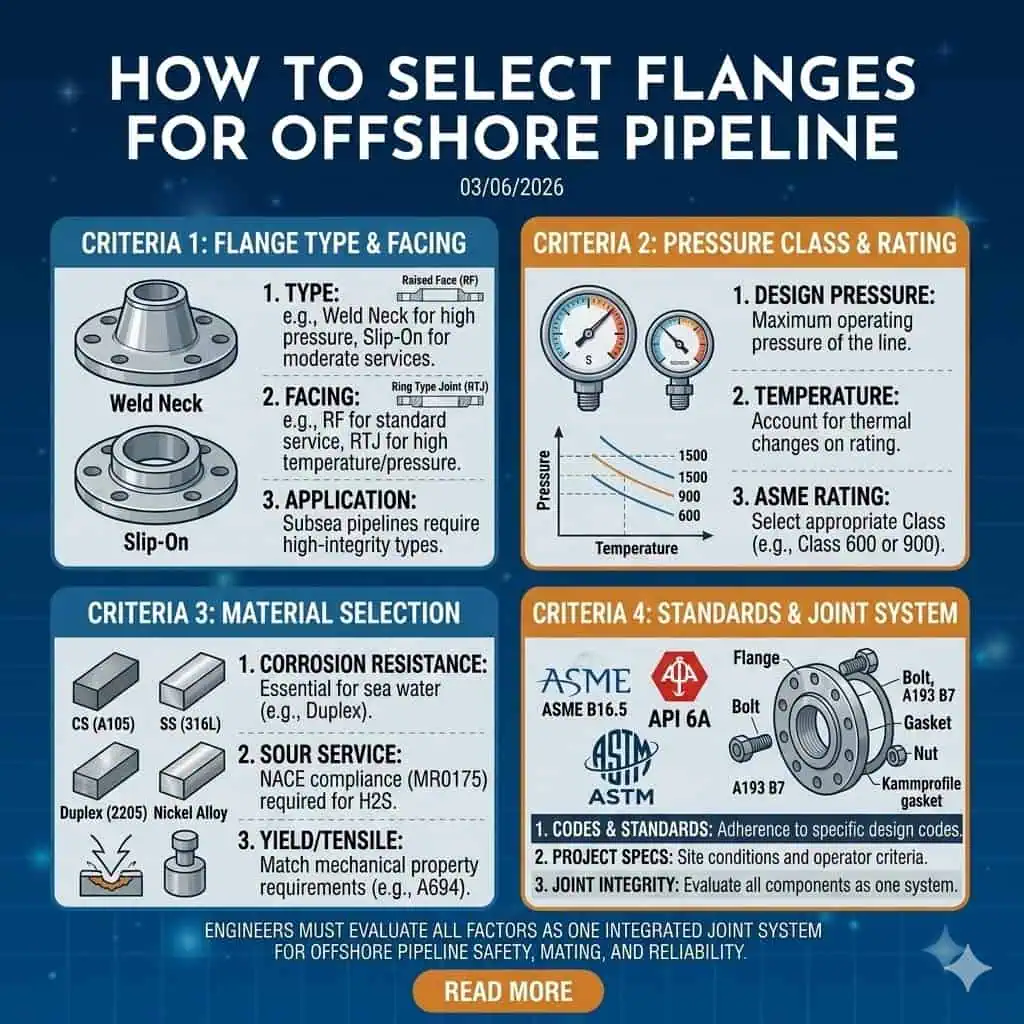
To select flanges for offshore oil and gas pipelines, engineers must evaluate flange type, facing, pressure class, material, and project standards as one joint system. Each factor affects pipeline safety, mating compatibility, installation risk, and long-term durability in marine exposure (salt spray, humidity, vibration, thermal cycling, and limited maintenance access). Certified manufacturers such as SUNHY can support audit-ready procurement when they provide controlled manufacturing, clear marking, and complete documentation packages.
Expert Insight:
A 30-year veteran consultant warns that traceability gaps (missing heat numbers, incomplete MTR/MTC, unclear inspection scope) are a common cause of offshore package delays. He recommends verifying documentation requirements before PO release, not after delivery.
If you want to know how to select flanges for challenging offshore environments, focus on the decision criteria and the verification steps below.
How to Select Flanges for Offshore Oil and Gas Pipelines
Start with the Actual Service Conditions
Define medium, pressure, temperature, salinity, and corrosion exposure
Engineers must first define real service conditions before deciding how to select flanges. Offshore systems commonly see chlorides, intermittent wetting/drying, vibration, and operational transients. The process medium (seawater, produced water, hydrocarbons, gas, chemical injection, or sour service) determines corrosion mechanisms and gasket/material compatibility. Pressure and temperature determine pressure class and material group selection. Salinity, splash-zone exposure, insulation conditions, and oxygen ingress can accelerate localized corrosion and sealing-face degradation.
- Define the service envelope: normal operation + startup/shutdown + upset events (surge, depressurization, thermal transients).
- Identify corrosion drivers: chlorides, H2S/CO2, oxygen, sand/erosion, stagnant zones, and crevices.
- State the location exposure: topside, splash zone, enclosed module, or submerged/subsea (project-dependent).
Expert Insight:
The consultant notes that skipping a documented service envelope often causes material mismatches (e.g., gasket degradation, chloride pitting, sour-service cracking risk) and later rework. He recommends recording medium, design pressure, design temperature, and corrosion assumptions as the first step.
Check installation location, maintenance access, and service life target
Installation location and maintenance access directly affect how to select flanges. Offshore platforms often have limited laydown space and restricted tool access. Engineers should confirm whether the joint can be assembled with the planned bolting method (torque, tensioning), inspected after installation, and serviced during shutdown windows. Service life targets influence material choice, coating strategy, cathodic protection interfaces, and the required documentation for future integrity management.
- Access constraint: Can the joint be aligned without forcing fit-up? Is there space for stud installation and tensioning tools?
- Inspection constraint: Can you visually inspect the facing, gasket seating, and bolt condition during maintenance?
- Service-life target: Define whether the joint is designed for “minimal intervention” service (higher verification burden) or periodic replacement.
Identify whether the priority is sealing reliability, corrosion resistance, fast installation, or cost control
Project priorities shape the flange selection process. Some offshore lines prioritize sealing reliability (high consequence lines, difficult access, or high pressure), while others prioritize corrosion resistance (chloride-rich service, splash zone exposure) or fast installation (shutdown scope). Cost control matters, but offshore economics usually favor lifecycle cost control over lowest first cost because rework and offshore interventions are expensive.
Expert Insight:
The consultant advises aligning priorities early. He warns that cost-driven substitutions without technical review often reappear as delayed commissioning, repeat leakage, or audit nonconformance.
A Practical Selection Sequence Engineers Actually Use
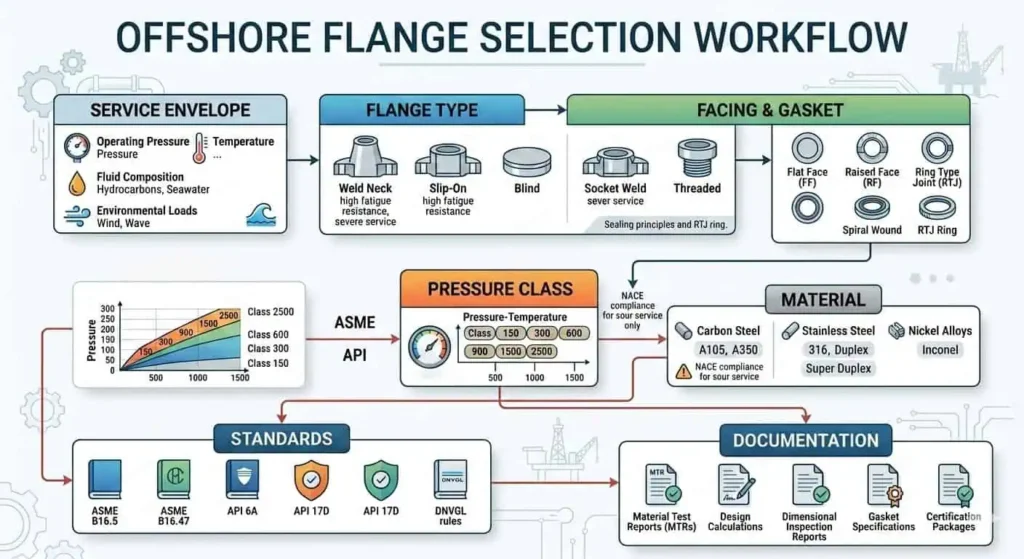
The following sequence shows how to select flanges for offshore pipelines in a logical, risk-managed way:
- Assess service conditions: Define design and operating envelope (pressure/temperature/medium), corrosion mechanism, and location exposure.
- Select flange type: Choose based on load/vibration sensitivity, accessibility, and joint criticality.
- Pick flange facing: Match facing to gasket technology and sealing reliability needs.
- Determine pressure class: Verify against pressure–temperature ratings for the selected material group and design standard.
- Choose material: Select for corrosion mechanism, mechanical strength/toughness, and fabrication constraints.
- Check standards: Confirm dimensional/rating standard (e.g., ASME B16.5/B16.47 or project-required equivalents) and any sour-service requirements where applicable.
- Review documentation: Require traceability, inspection scope, and certificates to match project QA and client acceptance criteria.
| Criteria | What to Verify in Offshore Practice |
|---|---|
| Flange Facing Types | Facing must match gasket type and assembly method (RF with spiral-wound/Kammprofile options; RTJ with correct ring and groove; FF only for specific mating requirements). |
| Pressure Class | Verify rating against design pressure/temperature for the selected material group and include surge/upset margin per project requirements. |
| Material Selection | Choose by corrosion mechanism (chlorides, sour service, erosion) and fabrication controls; confirm impact/toughness requirements if specified. |
| Compliance with Standards | Confirm flange dimensions/ratings, material specifications, marking, and inspection/testing requirements match the project standard set. |
Tip:
The consultant highlights that starting with price alone often leads to under- or over-specification. Follow the technical sequence above, then optimize cost with verified alternatives and a controlled documentation package.
Common Offshore Flange Selection Mistakes
Choosing by drawing habit instead of actual operating conditions
Many engineers select flanges based on old drawings or habits, not current pipeline needs. This can lead to mismatched material grades, wrong facing/gasket pairing, or pressure class selection that ignores temperature derating, surge events, or vibration loads.
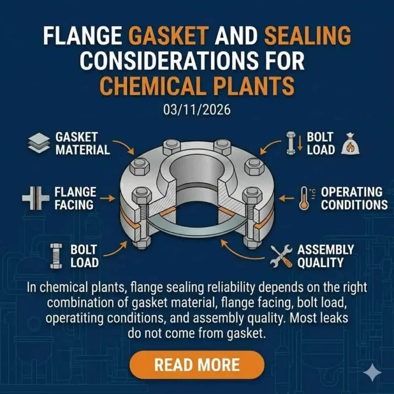
Ignoring gasket and bolting compatibility
Flange, gasket, and bolting must work together as a single sealing system. A flange that meets dimensional requirements can still leak if the gasket is incompatible or if bolt preload control is not achievable under field constraints. Offshore joints often fail by preload loss under vibration or thermal cycling, not by flange “strength” alone.
Focusing on initial purchase cost instead of total lifecycle cost
Choosing flanges based only on the lowest price can backfire offshore. Overrating pressure class increases weight, cost, and assembly burden. Under-rating increases leak and shutdown risk. Mixing dissimilar materials without review can accelerate galvanic corrosion. Ignoring thermal cycling or bolt preload retention increases fatigue and leak recurrence.
- Overrating pressure class increases cost and complicates installation.
- Mixing materials can increase galvanic corrosion risk at joints if not controlled.
- Ignoring thermal cycling can contribute to fatigue and preload loss.
- Neglecting bolt preload control can result in gasket failure and repeat leaks.
- Overlooking maintenance access can turn a minor leak into a major intervention.
Expert Insight:
The consultant warns that most costly offshore failures come from compatibility shortcuts (facing/gasket/bolting) or documentation gaps. He recommends evaluating lifecycle cost with verification steps, not assumptions.
In summary, how to select flanges for offshore pipelines means starting with service conditions, following a proven technical sequence, and verifying the joint system. This approach improves safety, reliability, and cost control for offshore oil and gas projects.
Flange Types and Applications in Offshore Pipelines
Which Flange Type Fits Which Offshore Use Case
Engineers select flange types based on load sensitivity, installation risk, and maintenance constraints. Each type serves a specific purpose in offshore pipelines.
| Flange Type | Key Characteristics | Recommended Use |
|---|---|---|
| Weld Neck | Tapered hub improves stress distribution and fatigue resistance | High-pressure lines, cyclic/vibration-prone service, critical joints |
| Slip-On | Easier fit-up; lower fatigue resistance than weld neck in severe cyclic service | Lower criticality and lower load environments with controlled installation |
| Blind | Isolation, pressure boundary closure | Isolation points, hydrotest boundaries, future tie-ins |
| Threaded | No welding; sensitive to vibration and sealant practice | Small-bore utility service where vibration and cyclic loading are controlled |
The most common flange types include weld neck, slip-on, blind, socket weld, threaded, and lap joint. In offshore service, weld neck flanges are frequently preferred for fatigue-sensitive or high-consequence joints. Slip-on flanges can be acceptable for lower criticality services if installation controls and loading environment are suitable. Blind flanges support isolation during maintenance and testing. Socket weld and threaded flanges are generally limited to small-bore or utility applications where vibration and crevice/corrosion risks are managed.
Expert Insight:
The consultant advises matching flange type to actual operating loads and access constraints. He notes that “easy to install” does not always mean “reliable offshore” if vibration and thermal movement are present.
How Layout and Maintenance Constraints Affect Flange Choice
Layout and maintenance needs influence which flange engineers select for offshore pipelines.
- Space limitations on skids, topside modules, and compact piping systems can restrict bolting access and gasket handling.
- Vibration, movement, and load transfer in offshore installations favor robust joints and controlled preload methods to reduce leak recurrence.
- Ease of inspection and replacement during shutdowns matters. Lap joint designs may support easier alignment in some maintenance scenarios, but they must still match service loads and sealing requirements.
Frequent inspection and maintenance are critical in offshore systems. Overlooking maintenance access can increase total intervention time and cost, especially where scaffolding, permits, and isolation steps dominate the schedule.
Expert Insight:
The consultant notes that many offshore delays are caused by “maintenance-unfriendly” joints. He recommends designing for realistic tool access and inspection tasks, not idealized drawings.
Practical Industry Case
Offshore water injection line: why weld neck flanges were selected to improve fatigue resistance and reduce leak risk
Offshore water injection lines can see cyclic pressure, pump-induced vibration, and temperature variation. Engineers selected weld neck flanges because the hub geometry improves stress transition and supports better fatigue performance. The package also specified controlled bolting procedures and inspection records to improve startup reliability.
Utility service skid: why slip on flanges were acceptable for non-critical lower pressure service
On a utility service skid, engineers selected slip-on flanges for non-critical, lower pressure service with controlled vibration. The selection focused on ease of fit-up and cost control, while still requiring verified facing/gasket compatibility and a documented tightening method to prevent early leakage.
Expert Insight:
The consultant highlights that selecting the right flange type controls both leak risk and lead time. He advises buyers to avoid “one-type-fits-all” specifications across mixed criticality lines.
Flange Facing Selection
Facing Types and Gasket Compatibility
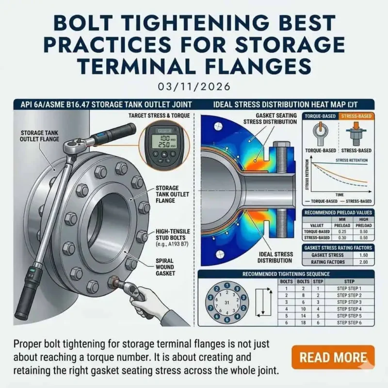
Selecting the right flange facing is essential for reliable sealing in offshore pipelines. Facing selection must match gasket technology, bolt preload control capability, and service severity.
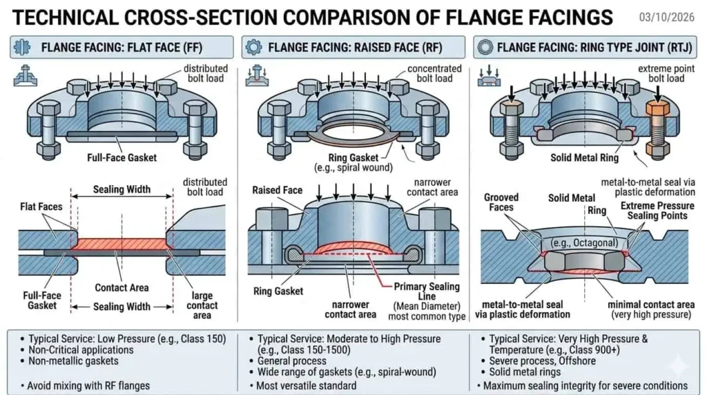
Raised face for common offshore piping systems with standard gasket solutions
Raised face is the most common flange facing for many offshore piping systems when service severity and project standards permit. It works with widely used gasket solutions (for example, spiral wound or other semi-metallic options) and concentrates gasket load on a smaller sealing area, which can improve sealing stability when preload control is consistent.
- Raised face flanges suit many oil and gas piping systems with appropriate gaskets.
- They support common maintenance workflows when access is adequate.
- Gaskets are widely available, but compatibility must still be verified for the medium and temperature.
Expert Insight:
The consultant recommends RF for many offshore packages as a practical balance of availability and sealing reliability—provided gasket selection and bolting control are specified, not assumed.
Ring type joint for high pressure and critical sealing service
Ring type joint (RTJ) facings are typically selected for high-pressure or high-consequence sealing service where project standards require higher sealing integrity and controlled ring/groove interfaces. RTJ joints require correct ring type and material selection, proper groove condition, and disciplined assembly.
- RTJ joints can tolerate demanding conditions when ring selection and groove condition are correct.
- They are commonly used on critical hydrocarbon service boundaries (project-dependent).
- RTJ performance depends strongly on ring/groove compatibility and controlled assembly.
Expert Insight:
The consultant advises specifying RTJ for critical lines when the project requires it and maintenance capability supports proper assembly and inspection. “RTJ is not a shortcut—it’s a higher-discipline joint,” he notes.
Flat face for specific low-pressure mating requirements
Flat face flanges are typically used for low-pressure service or specific mating requirements (for example, when connecting to brittle materials that should not be overstressed). Flat face joints generally require full-face gaskets and are not intended for severe cyclic loading unless specifically engineered and approved by project requirements.
- Flat face flanges generally require full-face gasket coverage.
- They are not the default choice for high-pressure or vibration-prone offshore joints.
- Use flat face only when the mating equipment and project specification require it.
Sealing Performance Under Offshore Conditions
Offshore pipelines face conditions that can reduce sealing stability: vibration, thermal cycling, pressure transients, and bolt preload loss. Design, gasket selection, and assembly control must account for these effects.
How vibration, thermal cycling, and bolt load loss affect sealing stability
Sealing performance can decline under offshore conditions if preload retention is not controlled. Vibration and thermal cycling can contribute to joint relaxation, embedment effects, and micro-movement at the interface. These mechanisms can increase leak risk over time, especially on joints near rotating equipment or in areas with cyclic loading. The practical control measures are consistent preload method, correct gasket technology, and verified installation discipline.
| Aspect | Offshore-Relevant Implication |
|---|---|
| Vibration Loads | Can accelerate preload loss and increase micro-movement at the interface, raising leak risk |
| Fretting / Micro-movement | May damage sealing surfaces and degrade gasket performance over cycles |
| Preload Control Method | Torque-only methods may be less consistent on large joints; controlled procedures and verification improve reliability |
Expert Insight:
The consultant urges buyers to consider offshore vibration and thermal swings when selecting facing and gasket solutions. He recommends documenting preload method and inspection acceptance criteria for critical joints.
Why facing choice must match gasket material and bolting design
Flange facing, gasket material, and bolting design must work together for a reliable seal. Raised face joints generally pair with soft/semi-metallic gaskets, while RTJ joints require compatible metal ring gaskets. Using the wrong combination can cause leakage, gasket damage, or joint instability.
- Match gasket type to the flange facing and the medium/temperature.
- Specify the bolting method and verification steps for preload consistency.
- Confirm manufacturer recommendations and project standards for the joint system.
How incorrect facing selection creates recurrent leakage problems
Incorrect facing–gasket pairing is a common cause of recurrent leakage. For example, installing a spiral wound gasket on an RTJ groove is a mismatch and can lead to poor seating and leakage. Similarly, using an RF gasket solution outside its service envelope can increase startup leak risk.
Expert Insight:
The consultant warns that repeat leaks often trace back to “compatibility shortcuts.” He recommends confirming facing, gasket type, and bolting method as a package before approving any flange order.
Practical Industry Case
Produced water line sealing issue caused by mismatch between flange facing and gasket type
A produced water line experienced repeat seepage after startup. Investigation found a mismatch between the facing requirement and the installed gasket type. After replacing the gasket with the correct facing-compatible solution and documenting the assembly method, leak recurrence reduced significantly.
Offshore hydrocarbon service line upgraded from RF to RTJ to improve sealing reliability under pressure fluctuations
An offshore hydrocarbon line experienced leakage during pressure fluctuations and thermal cycling. The project upgraded the joint specification (including facing strategy and installation controls) to improve sealing reliability. The improvement was achieved through combined changes: facing selection, gasket compatibility, and controlled preload verification.
Expert Insight:
The consultant highlights that facing changes only work when the project also controls gasket selection, groove condition, and bolting method. “Upgrading facing without upgrading assembly discipline is a false fix,” he notes.
Pressure Class Choice for Offshore Flanges
Understanding Pressure Ratings Beyond the Nameplate
Difference between nominal class and actual operating capacity
The nominal class on a flange nameplate must be verified against pressure–temperature ratings for the selected material group and standard. Actual allowable pressure depends on material grade, design temperature (derating at elevated temperatures), flange size, and project design rules. Offshore projects should also consider hydrotest pressure, transient surge, and future operating changes if specified.
- Material and alloy type affect strength and temperature derating behavior.
- Temperature impacts allowable pressure; higher temperatures generally reduce rating capacity.
- Size and flange series affect pressure–temperature ratings and bolting loads.
Expert Insight:
The consultant warns that relying only on the nameplate can lead to under- or over-specification. He advises verifying material grade, design temperature, and the governing standard tables before approval.
Why temperature, material grade, and design code all affect final pressure capability
Temperature, material grade, and design code collectively determine final pressure capability. High temperatures reduce allowable stress in many materials. Material grade defines baseline strength and toughness. Design codes (such as ASME flange standards where specified) provide the rating rules and dimensional requirements that must be met for safe operation.
| Factor | Impact on Pressure Capability |
|---|---|
| Temperature | Higher temperatures typically reduce allowable pressure for many material groups |
| Material Grade | Controls strength/toughness baseline and suitability for specified service |
| Design Code | Defines rating rules, dimensions, and acceptance requirements for the flange system |
Expert Insight:
The consultant notes that many supply chain issues come from missing the project’s governing standard set. He recommends confirming the design basis and client acceptance requirements before ordering.
How to Choose the Right Pressure Class for Pipeline Safety
Match design pressure and temperature to ASME class requirements
Engineers must match design pressure and temperature to the correct pressure class. Use the governing standard rating tables for the selected material group. Confirm whether hydrotest pressure or operator-specific design margins apply.
Allow margin for surge, upset conditions, and future operating changes
A margin strategy is essential when choosing a pressure class. Offshore pipelines can experience transient events such as surge, depressurization, or operational changes. The correct approach is to apply the project’s defined margin policy and verify the joint system can be installed and maintained at that class (weight, bolting, and access constraints matter).
- Review historical data for pressure spikes if available.
- Consider future operating changes and tie-in plans if defined.
- Confirm that installation method and bolting access remain feasible at selected class.
Expert Insight:
The consultant stresses that missing surge/upset considerations can lead to leak risk, while uncontrolled overspecification can create unnecessary weight and lead-time impacts.
Avoid under-specification that increases leak and shutdown risk
Under-specifying pressure class increases leak and shutdown risk, especially when transients and temperature derating are ignored. Savings from a lower class are often outweighed by rework, delay, and offshore intervention cost if the joint fails acceptance or leaks after commissioning.
Practical Industry Case
Offshore export line project where Class 600 was selected instead of Class 300 because of upset pressure and long-term safety margin
An offshore export line package included upset pressure scenarios and restart transients. The engineering team selected a higher pressure class to maintain margin under defined conditions and reduce leak risk during surges. The decision was supported by rating verification, installation feasibility checks, and documented acceptance criteria.
Lesson learned from overspecification: when a higher pressure class increased cost and lead time without adding real project value
In another project, the team selected a higher pressure class than required by the verified service envelope. The selection increased cost and lead time and added assembly burden without operational benefit. The lesson is to right-size class using verified pressure–temperature ratings and project margin policy, not habit.
Expert Insight:
The consultant advises buyers to avoid both under- and over-specification. He recommends confirming rating tables, installation feasibility, and acceptance scope with certified manufacturers before finalizing.
Material Selection for Offshore Flanges
Corrosion Resistance and Durability in Marine Environments
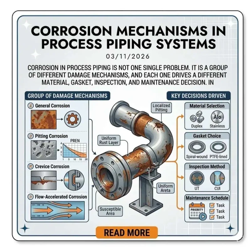
Selecting the right material for offshore flanges is critical for long-term durability and corrosion resistance. Marine environments expose joints to chlorides, wet/dry cycling, and high humidity. Material selection should follow corrosion mechanism and fabrication controls, not popularity.
| Material Type | Properties | Applications |
|---|---|---|
| Stainless Steel (304, 316) | Better general corrosion resistance than carbon steel; chloride pitting risk depends on chloride level and temperature (typical offshore range varies by exposure) | Moderate chloride exposure, topside piping, chemical systems (project-dependent) |
| Duplex and Super Duplex | High strength and improved resistance to chloride-related corrosion mechanisms when properly specified and fabricated | Seawater/produced water systems, aggressive chloride exposure, marine service (project-dependent) |
| Titanium, Copper-Nickel | Specialized corrosion performance for selected marine systems | Seawater/desalination/marine systems where justified by design life and corrosion risk |
Carbon steel for controlled environments with coating and corrosion protection strategy
Carbon steel can be cost-effective where corrosion exposure is controlled through coatings, insulation strategy, and cathodic protection integration. This is more suitable for non-critical services where inspection access and maintenance planning are realistic. Offshore projects should explicitly define the corrosion protection strategy if carbon steel is used.
Expert Insight:
The consultant advises confirming that coating scope, inspection access, and maintenance planning are defined before approving carbon steel offshore. He warns that “carbon steel without a protection plan is a schedule risk.”
Stainless steel for improved corrosion resistance in chloride-containing service
Stainless steel, especially 316 series, can be used in some chloride-containing services, but it is not automatically “seawater-proof.” Suitability depends on chloride concentration, temperature, oxygen content, and exposure type (immersed vs splash). Verify corrosion mechanism and project material selection rules.
Duplex and super duplex for aggressive offshore conditions requiring strength and corrosion performance
Duplex and super duplex materials are often selected for more aggressive chloride exposure because they combine strength with improved corrosion resistance when properly specified and fabricated. Welding procedure control and material verification are important to preserve corrosion performance.
Alloy materials for highly demanding sour, corrosive, or special process media
Special alloys may be required for sour service, chemical injection, or severe corrosion mechanisms where standard steels are not adequate. Selection should be based on corrosion mechanism, mechanical requirements, fabrication controls, and documented service envelope. When sour service applies, material limits are often governed by project requirements aligned to NACE MR0175 / ISO 15156 (where applicable).
Material Compatibility with Pipeline Media
Material compatibility with the pipeline medium is a safety and reliability requirement. The wrong material can lead to corrosion, cracking, leaks, or rework. Use corrosion mechanism and service envelope as the decision basis.
| Flange Material | Advantages | Suitable Conditions |
|---|---|---|
| Carbon Steel | Cost-efficient; broad availability | Controlled corrosion environments with defined protection strategy |
| Stainless Steel | Improved corrosion resistance vs carbon steel | Moderate chloride/chemical exposure (verify pitting/crevice risk) |
| Duplex Alloys | High strength with improved chloride corrosion resistance when properly specified | Seawater/produced water and more aggressive marine exposure (project-dependent) |
Seawater, produced water, hydrocarbons, gas, sour service, and chemical injection lines
Each medium presents different risks. Seawater and produced water often drive chloride-related corrosion mechanisms. Hydrocarbons and gas may introduce pressure transients and temperature cycling issues. Sour service may require additional material limits and documentation. Chemical injection lines can require higher-alloy materials depending on chemistry and temperature.
Why corrosion mechanism matters more than material popularity
Corrosion mechanisms (pitting, crevice corrosion, galvanic corrosion, sour-service cracking risk, erosion-corrosion) determine material selection. “Popular” materials are not automatically appropriate. Offshore selection should be justified by mechanism and documented assumptions, especially for high-consequence joints.
How to balance corrosion resistance, strength, fabrication difficulty, and budget
Engineers balance corrosion resistance, mechanical strength/toughness, fabrication complexity, inspection burden, and budget. Duplex alloys can be a practical compromise when chloride exposure is significant and strength is needed, but fabrication controls must be managed. Carbon steel can be viable for certain utilities if corrosion protection is defined. These are typical engineering trade-offs and depend on exposure, temperature, and design life targets.
Expert Insight:
The consultant recommends selecting materials by mechanism and verification scope. He warns that unreviewed substitutions create both integrity risk and audit risk.
What Buyers Should Check Before Approving a Material Option
Buyers must verify material quality and traceability before approving any flange for offshore use.
| Factors to Consider | Description |
|---|---|
| Material Specifications | Confirm the material specification and grade match the PO and project requirements. |
| Quality System Evidence | Verify supplier quality system evidence (e.g., ISO 9001) and inspection scope consistency. |
| Compliance with Standards | Check dimensional standard, material standard, and required testing/inspection records match the project spec. |
| Intended Application | Confirm service envelope, corrosion mechanism, and installation constraints before final approval. |
- Choose flange material based on intended service envelope and inspection plan.
- Match flange material with pipe material where required and review galvanic compatibility for mixed metallurgy.
- Confirm fabrication/welding controls for materials sensitive to heat input or phase balance (project-dependent).
MTC review, heat number traceability, PMI, corrosion-related testing, and compliance with project specs
Buyers should review Mill Test Certificates (MTC), confirm heat number traceability, and require PMI when specified or when criticality warrants. Corrosion-related testing and compliance with project specifications reduce the risk of receiving incorrect materials. The required scope depends on project QA and service criticality.
Risks of substituting materials without full technical review
Substituting materials without technical review is a common offshore risk. Even “equivalent” materials may change corrosion performance, toughness, welding procedure requirements, and documentation acceptance. Any substitution should be reviewed and approved per project change control.
Expert Insight:
The consultant urges clients to demand complete MTC/MTR traceability and clear inspection scope for every offshore flange order. He warns that documentation gaps or unauthorized substitutions often trigger client rejection or re-inspection.
Practical Industry Case
- Some offshore EPC packages require operator-specific approvals or third-party inspection witnessing for critical flanges. Suppliers must demonstrate controlled material sourcing and traceability to meet these requirements.
- Marine exposure often drives higher corrosion performance requirements for seawater/produced water systems, which increases the importance of correct material selection and fabrication controls.
Seawater service line where duplex flange selection reduced corrosion risk compared with conventional stainless steel
A seawater service line experienced localized corrosion risk under chloride exposure. Engineers selected duplex flange material based on corrosion mechanism and design life targets, supported by documentation and verification controls. The change reduced corrosion-related intervention frequency (typical offshore benefit depends on chloride level, temperature, and exposure conditions).
Carbon steel flange with coating system used successfully in a non-critical offshore utility application with proper maintenance planning
On a non-critical utility line, engineers used carbon steel flanges with a defined coating and inspection plan. The approach was cost-effective because access for inspection and maintenance was feasible. The key lesson is that carbon steel success offshore depends on protection strategy and realistic maintenance planning.
Expert Insight:
The consultant highlights that success comes from matching material to exposure and verification scope, not from a single “best material” rule.
End Connections, Welding Methods, and Installation Risks
End Connection Choice in Real Offshore Fabrication
Butt weld ends for structural integrity and long-term reliability
Butt weld ends generally provide the best structural continuity for critical offshore pipelines because they reduce stress concentrations and support better fatigue performance when welding quality is controlled. Offshore projects should verify welding procedures, fit-up tolerances, and inspection scope as part of joint integrity control.
Expert Insight:
The consultant emphasizes verifying welding procedure qualification, material compatibility, and inspection scope for butt weld ends. Poor welding control can compromise sealing alignment and schedule reliability.
Socket weld and threaded options for small bore systems and their limitations
Socket weld and threaded flanges can suit small bore systems but have limitations offshore. Socket welds may introduce crevice and corrosion risks at the root area, while threaded joints can be sensitive to vibration and sealant/assembly practice. These options are typically limited to utility service or non-critical applications where vibration and corrosion drivers are controlled.
- Socket welds can concentrate corrosion at crevice-like regions if conditions permit.
- Threaded joints can loosen under vibration if not controlled.
- Both types require careful inspection and installation discipline to reduce leak risk.
Welding Quality Control Matters as Much as Flange Design
Welding quality control is as important as flange design in offshore pipeline installations. Fit-up quality, heat input control, distortion management, and coating/insulation interface control all affect flange alignment and sealing stability. Offshore repairs are expensive, so prevention is driven by controlled fabrication and verification.
- Corrosion protection and surface preparation reduce moisture-driven degradation at weld zones.
- Distortion control reduces alignment and facing flatness risks.
- Long-term reliability depends on both design and installation quality.
Welding procedure qualification, welder qualification, and NDT expectations
Offshore projects typically require verified welding procedures, qualified welders, and defined NDT scope. The exact acceptance criteria depend on project specification and operator requirements. NDT (UT/RT/MT/PT where applicable) supports defect detection before commissioning.
Why poor fit-up and welding distortion can undermine flange sealing performance
Poor fit-up and welding distortion can undermine flange sealing performance even when materials are correct. Distortion can cause facing non-parallelism and uneven gasket loading. Engineers should treat alignment and distortion as sealing risks, not only “fabrication issues.”
Expert Insight:
The consultant advises prioritizing QA/QC inspections during fabrication. He notes that many offshore leak investigations trace back to alignment and distortion, not material defects.
Practical Industry Case
Fabrication delay caused by mismatch between flange end preparation and site welding practice
A project experienced fabrication delay when flange end preparation did not match the site welding practice and fit-up method. The team had to re-machine components and re-qualify the work scope. This case highlights the need to align procurement details with fabrication practice before shipment.
Leakage issue traced back to installation alignment rather than flange material failure
A persistent leak occurred at a flange joint after reassembly. Investigation showed poor installation alignment was consuming bolt load and creating uneven gasket compression. After correcting alignment and controlling preload method, the leak stopped—demonstrating why fit-up control is a sealing control.
- Offshore repairs often require specialized logistics and increased downtime risk.
- Corrosion at weld zones can drive long-term integrity issues if coating/insulation interfaces are not controlled.
- Distortion and alignment issues can create recurrent leaks even when documentation is complete.
Expert Insight:
The consultant recommends managing alignment and weld quality as part of joint integrity control and verifying the inspection scope during fabrication to avoid expensive offshore interventions.
Standards and Certifications Buyers Should Verify
Core Offshore Flange Standards
ASME dimensional and pressure class standards
Buyers must verify the dimensional and rating standard required by the project (commonly ASME B16.5/B16.47 or project-required equivalents). Using mismatched standards can create bolt pattern incompatibility and costly rework, even when materials are correct.
Expert Insight:
The consultant explains that mismatched dimensional standards are a common offshore rework cause. He urges buyers to confirm the governing standard set and marking requirements before approval.
ASTM material standards
ASTM material specifications define chemical composition, mechanical properties, and test requirements. Buyers should verify that the MTC/MTR references the correct ASTM/ASME material specification and grade required by the project. “ASTM” is typically a specification basis, not a standalone “certification.”
DIN and ISO requirements when project specifications require them
Some projects require DIN/EN or ISO-based standards for dimensions and material requirements. This is common on European-led projects or where operator specifications standardize on DIN/EN. Buyers should confirm whether mixing ASME and DIN/EN components is permitted and how gasket/bolting interfaces will be managed.
NACE, EN 10204 3.1, and project-specific offshore documentation requirements where applicable
Where sour service applies, projects may require alignment with NACE MR0175 / ISO 15156 limits. EN 10204 certificates support material inspection documentation: 3.1 is typically an inspection certificate issued by the manufacturer, while 3.2 generally involves additional independent witnessing/validation per project requirement. Offshore projects may also require coating records, NDT reports, PMI scope, and full traceability for client acceptance.
| Certification | Description |
|---|---|
| ISO 9001:2015 | Quality management system for consistent manufacturing and documentation control |
| ASME B16.5/B16.47 | Dimensional and rating standard set (project-dependent) |
| ASTM material specification compliance | Material requirements verified through MTC/MTR |
| NACE MR0175/ISO 15156 | Material limits for sour service where applicable |
| EN 10204 3.1/3.2 | Inspection certificate scope (3.1 manufacturer certificate; 3.2 with additional independent witnessing per requirement) |
| PED 2014/68/EU | Pressure equipment compliance where EU regulatory scope applies |
| API 6A | Where applicable for wellhead/pressure-control equipment packages (project-dependent) |
| NORSOK | Project standards often referenced in North Sea-related specifications (project-dependent) |
Standard dimensions and documentation scope must match project requirements to ensure safe installation and smooth client acceptance.
Documentation and Compliance for Audit-Ready Procurement
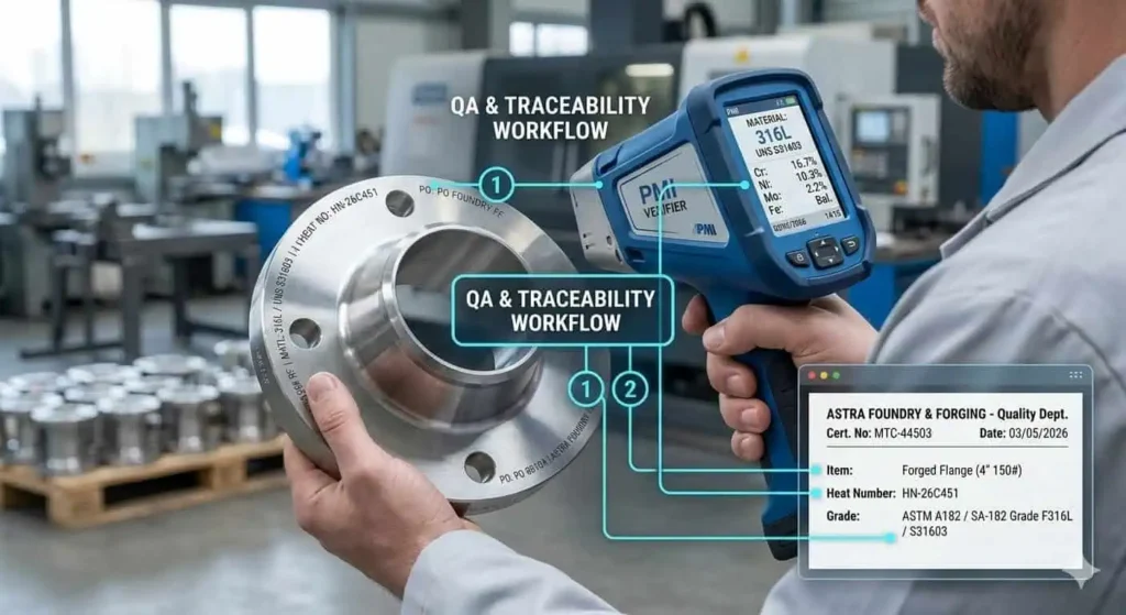
Material test certificates, dimensional inspection reports, PMI, NDT, coating records, and traceability documents
Audit-ready procurement requires complete documentation for each flange package. Buyers typically verify MTC/MTR, dimensional inspection reports, PMI records where required, NDT results per spec, coating/packing records, and traceability documents linked to heat numbers and markings.
| Aspect | Description |
|---|---|
| Vendor Qualification | Confirms supplier capability to meet dimensions, material specifications, and documentation scope |
| Material Specifications | Defines required material grade, heat treatment, and test scope |
| Procurement Inspections | Verifies dimensional, marking, and inspection results during production |
| Risk Reduction | Prevents wrong material/standard deliveries and reduces rework risk |
| Compliance and Safety | Supports regulatory and client acceptance requirements |
| Cost Efficiency | Early detection avoids offshore rework and schedule impacts |
Expert Insight:
The consultant notes that incomplete documentation is a frequent cause of project delay. He recommends confirming certificate format, required scope, and traceability linkage before shipment.
Why documentation quality directly affects project approval and site acceptance
High-quality documentation speeds approval and site acceptance because inspectors can verify compliance without re-testing or re-inspection. Poor records can lead to hold points, rejected lots, or unplanned third-party inspection.
What EPC buyers and QA teams typically ask before issuing final approval
EPC buyers and QA teams typically require proof of standard compliance, material certificates, inspection reports, and traceability linkage. They may also require third-party witnessing for critical items. Clarifying this checklist early reduces downstream disputes.
Practical Industry Case
Project approval delay caused by incomplete traceability records
A project faced schedule delay because traceability records were incomplete for several items in an offshore flange package. Client acceptance required linked heat numbers and complete inspection certificates for the lot. The team had to perform re-inspection and document reconstruction, increasing cost and delaying installation.
Expert Insight:
The consultant advises verifying traceability scope and acceptance format before shipment. “If the client can’t verify it on day one, it becomes a delay,” he notes.
How complete documentation helped accelerate offshore client inspection and shipment release
In another package, the supplier provided complete documentation, clear marking, and inspection scope aligned to client requirements. The client completed inspection quickly and released the shipment without additional hold points. The lesson is that documentation quality is a schedule control tool.
Standard compliance, complete documentation, and traceability reduce offshore project risk and delay.
How to Compare Offshore Flange Suppliers
What Makes a Manufacturer Reliable for Offshore Projects
A reliable manufacturer for offshore projects must meet strict technical and operational requirements. Dependable suppliers demonstrate offshore specification experience, controlled material sourcing, consistent machining accuracy, defined inspection capability, and predictable delivery with complete export documentation.
| Criteria | Description |
|---|---|
| Design | Design review aligned to service envelope and project standard set reduces mismatch risk |
| Construction | Controlled forging, machining, and heat treatment processes support consistency |
| Integrity Management | Traceability and inspection records support long-term maintenance and audits |
| Operational Safety | Compliance with standards and verification scope reduces leak and failure risk |
| Cost Efficiency | Right-spec selection and stable delivery reduce rework and offshore intervention costs |
Experience with offshore oil and gas specifications
Manufacturers with offshore project experience understand specification structure, documentation requirements, and common failure modes. They can support correct standard selection and verification scope planning.
Material sourcing control and batch traceability
Reliable suppliers control material sourcing and maintain batch/heat traceability. This ensures that delivered flanges match the specified material grade and test requirements.
Machining accuracy, inspection capability, and delivery consistency
Machining accuracy and inspection capability reduce fit-up issues and field rework. Delivery consistency reduces supply chain risk and protects commissioning schedules.
Ability to support special materials, urgent lead times, and complete export documents
Offshore projects often require special alloys, urgent replacements, and complex documentation. Suppliers who can support these requirements reduce operational risk during fast-track packages.
Expert Insight:
The consultant advises prioritizing suppliers with controlled documentation, traceability, and proven offshore delivery performance. “A technically correct flange that arrives without acceptable records is not usable offshore,” he notes.
Questions Buyers Should Ask Before Placing an Order
Buyers should ask key questions to confirm supplier reliability and project fit.
| Question | Explanation |
|---|---|
| How to Verify Supplier’s Reliability? | Review quality system evidence, request MTC/MTR samples, confirm inspection scope, and verify delivery performance for similar offshore packages. |
| Do All Suppliers Have Minimum Order Quantities? | MOQs vary by product and material; confirm trial order policy and spare strategy early. |
| Are Free Samples Typically Offered? | Sampling policy depends on standard vs custom items; confirm cost, lead time, and inspection scope for samples. |
| Can I Visit the Manufacturing Facility? | Factory audit (in-person or virtual) helps verify process control and inspection capability. |
| What Is the Typical Lead Time After Sample Approval? | Lead time varies by material, class, size, and inspection scope; confirm critical-path items early. |
| Can International Suppliers Handle Global Shipments? | Confirm export packing, corrosion protection, document set, and customs requirements to avoid damage or delays. |
Can the supplier provide full traceability and third-party inspection support
Confirm whether the supplier can provide full traceability and support third-party witnessing where the project requires it. Define what “traceability” means in the contract (heat number linkage, marking, certificate format, lot separation).
Can they handle project documentation and customer-specific QA requirements
Confirm document format, required scope (MTC/MTR, dimensional reports, PMI, NDT, coating records), and submission timing before shipment.
Do they have proven experience with offshore, marine, or corrosive service applications
Experience with similar service conditions reduces risk. Ask for examples aligned to comparable media, exposure, and documentation scope (without disclosing confidential client information).
Expert Insight:
The consultant recommends verifying supplier documentation processes and inspection capability early. He notes that this reduces procurement disputes and protects commissioning schedules.
Practical Industry Case
- In integrity-sensitive projects, properly specified anchor or stability-related flange solutions can reduce displacement risk and leak potential when they match loads and verification scope.
- In dynamic load environments, joint stability depends on load control, correct standard selection, and traceable verification—not on “stronger parts” alone.
Why one offshore contractor changed suppliers after repeated document inconsistency and late delivery
An offshore contractor changed suppliers after repeated document inconsistency and late delivery. The contractor selected a manufacturer with stronger traceability control and predictable delivery, reducing client hold points and schedule risk.
How qualified manufacturer support reduced procurement risk in a fast-track offshore package
A fast-track offshore package required urgent delivery and full compliance. The project team selected a qualified manufacturer with verified documentation processes and inspection scope. The supplier’s support reduced procurement risk and helped keep the package on schedule.
Expert Insight:
The consultant highlights that offshore procurement success is driven by documentation readiness and delivery reliability, not only unit price.
Offshore Flange Selection Checklist for Buyers and Engineers
Selecting the right flange for an offshore pipeline requires review at every stage. Buyers and engineers should use a structured checklist to ensure safety, compliance, and long-term reliability.
Technical Checklist Before Final Approval
Engineers and buyers must confirm all technical details before approving pipe flanges for offshore use.
| Checklist Item | Description |
|---|---|
| Service conditions | Confirm medium, pressure, temperature, salinity, exposure category, and corrosion mechanism assumptions. |
| Flange type & facing | Match flange type and facing to loads, sealing reliability needs, and maintenance access. |
| Pressure class | Verify rating against design envelope and project margin policy; confirm installation feasibility at selected class. |
| Material review | Confirm material selection by corrosion mechanism, strength/toughness requirements, and fabrication controls. |
| Gasket & bolting | Verify gasket compatibility and define bolting/preload method and acceptance checks. |
| Standards & testing | Align standards, testing, and documentation scope with project specification and client acceptance. |
Expert Insight:
The consultant advises buyers to insist on heat-traceable MTC/MTR and clear inspection scope. He warns that missing toughness/impact requirements for fatigue-sensitive systems can create rework risk. Always require visual and dimensional inspection to the specified dimensional standard (e.g., ASME B16.5 or EN 1092-1 where applicable).
A detailed technical checklist helps prevent mismatches and ensures the right flange fits the pipeline’s operating environment.
Additional technical requirements for offshore pipe flanges include:
| Checklist Item | Description |
|---|---|
| Specify Material | If high-strength pipeline flanges are required, specify the correct material standard/grade per design (e.g., ASTM A694 grade as applicable) on the PO. |
| MTR Requirements | Require MTC/MTR referencing the correct material specification and grade used for the order. |
| CVN Temperature | Specify required impact test temperature and acceptance scope if required by the project for low-temperature or critical service. |
| Flange Standards | Call out dimensional standard (ASME B16.5 or EN 1092-1) and rating class as required. |
| Impact Data | For critical or low-temperature systems, include toughness/impact requirements in the contract package. |
| Heat Traceability | Insist on heat-traceable MTC/MTR and marking linkage; define lot separation rules where required. |
| Mechanical Tests | Confirm required mechanical test scope and documentation format for client acceptance. |
| NDT Requirements | Define NDT scope (UT/RT/MT/PT where applicable) if required by spec or client witness plan. |
| Visual Inspection | Visual & dimensional inspection to the specified dimensional standard and project acceptance criteria. |
This table ensures buyers and engineers cover critical points before final approval of offshore flange packages.
Procurement Checklist Before Purchase Order
Buyers must verify procurement details to secure the right flange and avoid supply chain risks.
- Confirm drawings and BOM match pipeline layout and the required dimensional standard.
- Define inspection and testing requirements, including any client witness points.
- Require MTC/MTR and traceability linkage for each lot of flanges.
- Specify export packing and corrosion protection for offshore shipment to prevent damage.
- Arrange third-party inspection or client witness scope where required by project specification.
Expert Insight:
The consultant recommends confirming documentation scope and acceptance format before PO release. He notes that unclear packing and certificate requirements often cause offshore delays and additional cost.
A procurement checklist protects buyers from costly mistakes and ensures the flange arrives ready for installation.
Summary:
Buyers and engineers should use both technical and procurement checklists to select pipe flanges for offshore pipelines. These steps help ensure the flange meets project requirements and supports safe, reliable operation.
To select the right flange for offshore oil and gas pipelines, engineers should follow these steps:
- Assess service conditions.
- Choose the correct flange type and facing.
- Verify pressure class and material.
- Check compliance with industry standards and documentation requirements.
Expert Insight:
A 30-year veteran consultant suggests consulting certified manufacturers like SUNHY for audit-ready solutions. For complex packages, engineers should confirm the standard set, documentation scope, and assembly constraints before finalizing.
FAQ
What is the most important factor when selecting offshore flanges?
Service conditions and the full joint system are the most important factors. Selection should match medium, pressure–temperature envelope, corrosion mechanism, and installation constraints—then verify facing/gasket/bolting compatibility.
A 30-year veteran consultant says, “Always match flange type and material to pressure, temperature, and medium—and confirm how the joint will be assembled offshore. Skipping this step leads to leaks and costly rework.”
How can buyers avoid common purchasing pitfalls?
Buyers should demand full documentation and traceability aligned to client acceptance. Confirm what certificates are required, how heat numbers link to markings, and whether witness/third-party scope applies.
- Request Mill Test Certificates / MTRs and clarify EN 10204 scope if specified
- Verify supplier quality system evidence and inspection capability
- Review past offshore package experience and delivery performance
The consultant warns, “Missing documents cause delays and audit failures. Define acceptance format before shipment.”
Which flange material works best for seawater pipelines?
Duplex or super duplex is often selected for seawater-related exposure because it can offer strong corrosion performance and strength when properly specified and fabricated. Final selection depends on chloride level, temperature, exposure category, and project requirements.
The consultant notes, “For seawater exposure, verify corrosion mechanism and fabrication controls. Material choice without verification is not risk control.”
Why does documentation quality affect project success?
Complete documentation speeds approval and site acceptance because it reduces hold points. If the client cannot verify compliance quickly, packages may be held for re-inspection.
| Document Type | Purpose |
|---|---|
| MTC/MTR | Material verification |
| NDT Reports (where required) | Quality assurance and defect verification |
| Traceability linkage | Audit compliance and lot identification |
The consultant says, “Incomplete records delay projects and increase supply chain risk.”
How can buyers control costs without sacrificing safety?
Control cost by right-sizing specifications and reducing rework risk, not by cutting verification steps. Confirm the service envelope, verify rating tables and material requirements, and standardize documentation packages for repeatability.
- Avoid overspecification that increases weight, lead time, and assembly burden
- Use verified materials and gasket/facing combinations for the service
- Work with certified manufacturers and lock down documentation scope early
The consultant advises, “Right-sizing specs and verifying supplier capability protect budgets and reduce offshore intervention risk.”