Key Takeaways: Measuring Butt Weld Fittings
- Identify the standard first: confirm whether the fitting is supplied to ASME B16.9, MSS SP-43, or an EN 10253 series requirement before checking take-off dimensions.
- Measure OD, not ID, to identify size: butt weld fittings are matched to pipe by outside diameter and NPS, not by inside diameter.
- Center-to-end is the critical spool dimension: most fabrication mismatches come from wrong take-off, not wrong OD.
- Use the right tools: digital calipers for OD and take-off, micrometers for wall thickness, and bevel or angle gauges for weld-end prep.
")
Stainless steel butt weld fittings are measured by outside diameter, nominal pipe size, wall thickness or schedule, and fitting take-off dimensions such as center-to-end or end-to-end. These measurements determine whether the fitting matches the pipe, maintains bore alignment, and can be welded without forced fit-up. For most factory-made wrought butt-weld fittings, dimensional requirements and tolerances are defined in ASME B16.9, while welding-end bevel preparation is covered by ASME B16.25. Common stainless material requirements for WP304/L, WP316/L, and similar grades are typically specified to ASTM A403/A403M.
The fastest way to avoid site rework is to verify three things before fabrication starts: the correct OD and NPS, the correct wall thickness, and the correct take-off dimension for the fitting series actually supplied. On stainless systems, a fitting that “almost fits” usually turns into forced alignment, distortion during welding, extra grinding, or repair welding later.
From a QA standpoint, a practical receiving and fit-up inspection plan focuses on dimensional verification plus traceability evidence. Common controls include:
- Dimensional checks for OD, overall length, and center-to-end using calibrated calipers or gauges and documented sampling
- Wall-thickness verification by micrometer and, when needed, UT spot checks where forming may thin the tangent area
- Review of the MTR or inspection certificate, with heat-number traceability and PMI spot checks where specified
- Fit-up checks on welding ends, including bevel condition, land or root face, and end roundness before release to fabrication
If your project requires strict traceability, it helps to keep dimensional records tied to part markings and the heat paperwork. For buyers and QA teams, this works best when dimensional checks are reviewed together with material certificate interpretation rather than as separate paperwork after the fact.
Key dimensions of stainless steel butt weld fittings
Nominal pipe size (NPS)
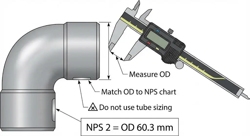
NPS is the naming system used to order pipe and butt weld fittings, but you do not measure NPS directly with a caliper.
NPS is a designation that corresponds to standardized outside diameters. For smaller sizes, the NPS number does not equal the actual OD. ASME highlights this distinction clearly: pipe uses standardized OD values, while tube is usually identified directly by OD under different sizing rules. For stainless pipe, the standard OD series is listed in ASME B36.19M.
Field example: A maintenance team measured about 60.3 mm OD and ordered “60 mm tube fittings.” The line was actually NPS 2 pipe, which uses the same OD but a different pipe-based designation and weld-end expectation. The reducers arrived with the wrong assumption behind the order and did not fit the line correctly. The real fix was to identify the pipe size from OD first, then specify NPS, schedule, and standard on the purchase order.
| Nominal Pipe Size (NPS) | Outside Diameter (OD) | Inside Diameter (ID) Variation |
|---|---|---|
| 12 inches and smaller | Fixed for each size | Decreases as wall thickness or schedule increases |
| Above 14 inches | OD and NPS align more closely | ID still varies with wall thickness |
Practical identification tip: measure OD first, then match OD to a pipe OD table based on ASME B36.10 or B36.19. Once NPS is identified, you can correctly interpret schedule and fitting take-off dimensions.
Outside diameter (OD)
OD is the physical measurement you can verify immediately at receiving and before fit-up.
The OD must match the pipe OD for the stated NPS so the welding ends align without offset. For stainless pipe and matching fittings, the OD series is standardized under ASME B36.19M. A quick OD check is often the fastest way to catch mixed pipe and tube assumptions or DN-only purchasing mistakes.
- Example OD checks, always confirmed against the project’s adopted OD table:
- NPS 1/2 (DN 15): OD ≈ 0.840 in or 21.3 mm
- NPS 1 (DN 25): OD ≈ 1.315 in or 33.4 mm
- NPS 4 (DN 100): OD ≈ 4.500 in or 114.3 mm
Field example: On a stainless spool, the OD matched the drawing, but the fitting end was slightly out-of-round. The welder had to pull the joint into place with clamps, creating internal mismatch and burn-through risk on the thin side. The better practice is to measure OD in at least two perpendicular directions at each end and correct or reject ends that exceed the project’s roundness limits before fit-up.
Wall thickness (Schedule)
Wall thickness controls fit-up tolerance, weld behavior, and whether the fitting actually matches the line schedule.
On stainless piping systems, Schedule 10S, 40S, 80S, and similar designations are common. Those schedule names tie back to standardized wall-thickness tables in ASME B36.19M. In practice, fittings are often described as matching the connected pipe schedule, but acceptance still has to be verified by measurement and by the adopted fitting standard.
Field example: A crew installed Sch.10S elbows into a Sch.40S line because the OD was correct and the markings were missed. The first sign of trouble was excessive root opening and poor penetration control at fit-up. The correction was to verify wall thickness during receiving inspection, require readable markings, and keep traceable paperwork attached to the lot before parts entered fabrication.

End-to-end and center-to-end (Take-off)
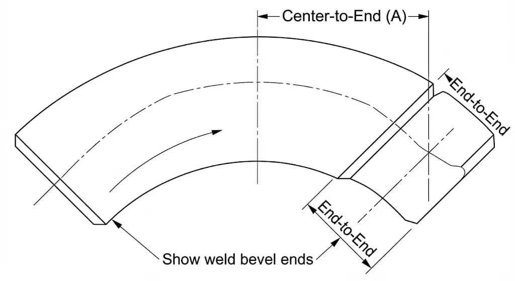
Take-off dimensions decide whether a spool lands correctly on supports and reaches the next weld point without forced fit.
End-to-end is used for straight fittings such as reducers or caps. Center-to-end, also called center-to-face, is the critical dimension for elbows and tees because it determines the turn point or branch location in the spool. In practice, many site rework problems are caused by take-off mismatch rather than OD mismatch because OD is usually easy to standardize, while take-off errors only become obvious when the spool is assembled.
Field example: A rack spool ended up about 6 mm short because the shop assumed a different elbow series than the drawing. The real correction was not “stretching” the spool in the field. It was measuring center-to-end on a sample elbow from the actual lot and locking the fitting series in the BOM before any pipe cutting started.
Standard Dimensions Chart (ASME B16.9)
Use the chart below as a practical check for long-radius elbows, which are among the most common butt-weld fittings.
| NPS (Size) | Outside Diameter (OD) | 90° LR Elbow Center-to-End |
|---|---|---|
| 1/2 | 21.3 mm (0.84″) | 38 mm (1.50″) |
| 3/4 | 26.7 mm (1.05″) | 38 mm (1.50″)* |
| 1 | 33.4 mm (1.32″) | 38 mm (1.50″) |
| 1-1/2 | 48.3 mm (1.90″) | 57 mm (2.25″) |
| 2 | 60.3 mm (2.38″) | 76 mm (3.00″) |
| 3 | 88.9 mm (3.50″) | 114 mm (4.50″) |
| 4 | 114.3 mm (4.50″) | 152 mm (6.00″) |
| 6 | 168.3 mm (6.63″) | 229 mm (9.00″) |
| 8 | 219.1 mm (8.63″) | 305 mm (12.00″) |
| 10 | 273.1 mm (10.75″) | 381 mm (15.00″) |
| 12 | 323.9 mm (12.75″) | 457 mm (18.00″) |
*For NPS 3/4 and smaller, always verify the adopted standard and fitting type because small-bore alternatives can vary in other product families. Use the full ASME B16.9 standard for the official dimensions and tolerances.
Dimensional Tolerances (ASME B16.9)
Knowing the nominal dimension is not enough. You also need the allowable tolerance to decide whether the part is acceptable for fabrication.
| NPS Range | Off-Angle (Q) | Off-Plane (P) | Center-to-End Tolerance |
|---|---|---|---|
| 1/2 to 4 | ± 1 mm | ± 2 mm | ± 2 mm |
| 5 to 8 | ± 2 mm | ± 4 mm | ± 2 mm |
| 10 to 12 | ± 3 mm | ± 5 mm | ± 3 mm |
| 14 to 16 | ± 3 mm | ± 5 mm | ± 3 mm |
This is a general tolerance guide only. Use the official tolerance table in ASME B16.9 for project QA acceptance.
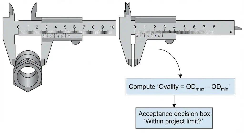
Additional measurements: bevel angle and ovality

Bevel condition and roundness affect weld quality before the welder even starts.
- Bevel preparation: standard butt-weld end-prep geometry is defined in ASME B16.25. Practical shop checks include bevel-angle consistency, root face or land uniformity, and end squareness.
- Ovality: measure OD in multiple orientations, typically 0° and 90°, on both ends. Oval ends create internal mismatch and uneven root opening, which is especially risky on thinner stainless wall sections.
- Thermal effects during measurement: stainless expands measurably with temperature. Stable shop temperature helps avoid drift when tolerances are tight.
Field example: A repair series showed lack of penetration at the 6 o’clock position. The real cause was not only welding technique. The bevel land varied, and one end was slightly oval, making the root tighter at the bottom of the joint. The correction was to re-face the bevel to a consistent land and re-round the end before fit-up.
Typical dimensions by fitting type
Different fittings have different critical dimensions.
ASME B16.9 covers a wide range of wrought butt-weld fitting types and sizes. In practical inspection, focus on the dimensions that actually control fit-up:
- Elbows: center-to-end, end roundness, and bend angle
- Tees: center-to-end on run and branch, branch alignment, and squareness
- Reducers: overall length, concentricity or eccentricity, and end prep on both ends
- Caps: OD, depth, and end prep
| Types of Fittings | Size Range (NPS) |
|---|---|
| 45° and 90° long-radius elbows, tees, crosses, caps | 1/2 – 48, within ASME B16.9 scope |
| Reducing elbows, returns, reducers, stub ends | Commonly supplied across small to medium sizes, depending on the adopted standard and supplier capability |
Good measurement is not only about getting a number. It is about proving that the fitting will assemble without forced alignment and will satisfy the adopted standard and WPS requirements.
How to measure pipe fittings accurately
Tools for measurement
Use tools that match the tolerance you actually need. Calipers are practical for OD and take-off checks, micrometers are more reliable for wall thickness, and circumference tapes help on larger diameters where calipers are not practical.
For most receiving inspections, a calibrated digital caliper is the main shop tool for OD and take-off checks. Shop calipers may show 0.01 mm resolution, but resolution is not the same as real measurement accuracy. Good technique and valid calibration matter just as much as the display. A concise reference is available from Mitutoyo’s guidance.
- Digital calipers for OD, inside checks, and shorter end-to-end or center-to-end measurements
- Tape measure or steel rule for longer take-off dimensions
- Micrometer for wall thickness
- Circumference tape for large outside diameters
- Angle or bevel gauge for weld-end verification
Step-by-step process to measure pipe fittings
Use a repeatable sequence so you do not miss the dimension that actually causes site rework.
- Confirm fitting type and standard.
Identify whether the part is an elbow, tee, reducer, cap, or other fitting. Confirm whether the project uses ASME B16.9, MSS SP-43, or an EN 10253 series requirement. Mixed standards are a common source of take-off mismatch. - Measure OD on each end.
Take at least two readings 90° apart on both ends. Record max and min to screen for ovality and handling damage. - Identify NPS from OD.
Use a pipe OD chart based on ASME B36.19M for stainless pipe. Do not rely on DN alone in mixed-spec jobs. - Measure wall thickness at multiple points.
Use a micrometer where accessible. On formed fittings, check near the tangent area as well as close to the end. Add UT spot checks if the application is more sensitive. - Verify take-off dimensions.
Measure end-to-end or center-to-end depending on fitting type. Compare with both the drawing and the adopted fitting standard before fabrication starts. - Check end prep before fit-up.
Inspect bevel condition, land uniformity, and squareness. Correct heavy dents or out-of-round ends before welding. - Document the results for traceability.
Record NPS, schedule, heat number or markings, measured OD, thickness, take-off, and inspector identification.
Tip: If a dimension barely fits, treat it as a nonconformance. Stainless butt-weld joints punish forced fit-up with distortion, mismatch, and repair welding.
Ensuring measurement accuracy
Accuracy comes from calibration, technique, and stable conditions, not from the display alone.
A practical method is to standardize how inspectors take readings, including the same contact points, the same measuring pressure, and the same orientation for repeated checks. Clean the fitting ends, remove burrs, and measure on a stable surface. If tolerances are tight, keep both tools and parts close to room temperature so thermal expansion does not distort the reading.
- Confirm calibration status and zero setting before use
- Clean the fitting surface before measuring
- Measure at multiple points to screen for ovality and formed-wall thinning
- Record results with units and location, such as end, tangent, or body
Common measurement mistakes to avoid
The most common mistakes are treating DN as a physical diameter and ignoring end condition.
- Mixing pipe and tube sizing: pipe OD follows NPS-based OD tables and does not equal the nominal size number on small sizes.
- Measuring only one point: a single OD reading can miss ovality and denting that later create internal mismatch.
- Skipping take-off checks: wrong take-off is a common cause of spool fit-up problems.
- Assuming schedule by eye: two fittings with the same OD can have very different wall thicknesses.
Note: If the part is already on site, it is much cheaper to find a mismatch with a caliper than later with cutting, grinding, and repair welding.
Standards and tolerances for stainless steel butt weld fittings
ASME B16.9 and ASTM standards
ASME B16.9 defines dimensional requirements for factory-made wrought butt-weld fittings, including key dimensions, tolerances, and markings. For stainless material requirements and grade designations commonly used in butt-weld fittings, ASTM A403/A403M is widely used for wrought austenitic stainless steel piping fittings.
| Standard | Key Requirements |
|---|---|
| ASTM A403/A403M | Material requirements for wrought austenitic stainless steel piping fittings, including grades and heat treatment |
| ASME B16.9 | Dimensional requirements, tolerances, and markings for factory-made wrought butt-weld fittings |
| ASME B16.25 | Butt-weld end-preparation requirements |
- Common stainless grades include WP304/L and WP316/L, depending on the project specification and corrosion environment.
- For light-wall corrosion-resistant fittings, projects may also reference MSS SP-43.
- For EU-directed pressure-equipment work, EN 10253 Part 3 or 4 may be referenced for stainless butt-weld fittings.
Tolerance ranges and compliance
Tolerances define how far a dimension may deviate before fit-up and design assumptions begin to break down. The reliable method is to confirm the adopted standard, measure the dimensions that control fit-up, and compare those readings with both the standard and any project-specific tolerance class. Where multiple standards are possible, that choice should be locked into the PO, ITP, and fabrication documents so the supply chain does not mix dimensional series.
| Control Item | Why It Matters |
|---|---|
| OD and end roundness | Controls internal mismatch and root-opening stability during welding |
| Wall thickness at end and tangent | Controls weldability and minimum remaining thickness after forming |
| Center-to-end or end-to-end | Controls spool geometry, support alignment, and forced-fit risk |
If you are sourcing from Sunhy or any other manufacturer, ask for a dimensional inspection record tied to heat numbers and marking photos. That is the shortest route to resolving disputes while keeping traceability intact.
Marking and documentation
Marking and documentation prove that the fitting you received is the fitting you specified.
At minimum, the marking should trace size, material grade, and adopted standard. On higher-spec projects, request inspection documents and make sure the heat number on the fitting matches the paperwork exactly.
Tip: Do not accept box paperwork that cannot be tied back to the heat numbers on the actual fittings. Once traceability breaks, the part becomes a risk item even if it measures correctly.
Importance of accurate measurement
Fit and weld integrity
Precise measurement reduces forced fit-up, minimizes mismatch, and improves weld quality.
When fittings actually meet the adopted dimensional standard and have correct weld-end prep, the joint is easier to align and weld without excessive clamp load. That means fewer repairs and less distortion, especially on thinner stainless wall sections where heat input matters.
- Correct alignment reduces internal mismatch and stabilizes root opening
- Consistent take-off prevents spool stress and spring during welding
- Uniform end condition improves repeatability against the WPS
- Standardized dimensions improve future maintenance interchangeability
Safety and operational reliability
Dimensional mismatch is often an early warning sign for later leak paths and fatigue problems.
A fitting that almost fits is often welded under stress. That stress can later become distortion, misalignment, or localized thinning after grinding and repair. When OD, NPS, schedule, and take-off are verified early, the system is built with fewer unknowns and less rework.
A common hidden failure mode is accepting the correct OD but missing wall-thickness mismatch or end out-of-roundness and then compensating with clamps. The joint may pass initial testing but still crack or leak earlier under vibration or thermal cycling.
Avoiding costly errors
Receiving inspection prevents the most expensive mistake: discovering mismatch after fabrication has already started.
Incorrectly sized stainless butt-weld fittings can cause leaks, weak welds, and unstable fit-up. These problems often lead to repairs, extra scrap, and commissioning delay.
- Repairs and downtime, because stainless cut-out and rework are labor-intensive
- Increased scrap, because one wrong elbow series can invalidate a whole spool
- Commissioning delay due to reinspection and retesting
Choosing a supplier with a documented inspection plan and traceability process helps reduce these risks. In practical receiving inspection, the best approach is to tie OD, wall-thickness, and take-off measurements to marking photos and heat paperwork so deviations can be resolved immediately.
Main steps for measuring stainless steel butt-weld fittings:
Measure OD first on both ends and in multiple orientations, identify NPS from the OD table, verify wall thickness at more than one location, and confirm take-off against the drawing and the standard. Finally, check end condition, including bevel and roundness, before fit-up.
Quick checklist for best results:
- Verify the adopted standard before measuring
- Measure both ends and record max and min OD to screen for ovality
- Confirm schedule by measurement rather than assumption
- Check take-off before cutting pipe
- Maintain traceability with marking, heat paperwork, and inspection record
Technical Review Basis
Reviewed for: butt-weld fitting dimensional verification, fit-up control, weld-end acceptance, and traceability checks for stainless piping fabrication.
Suggested reviewer title: Piping QA / Fabrication / Welding Inspection Engineer
Source basis: ASME B16.9 dimensional practice, ASME B16.25 weld-end preparation, ASME B36.19M stainless pipe OD and wall-thickness series, ASTM A403 material requirements, and practical receiving-inspection workflow.
Last updated: 2026-03-26
FAQ
How does Sunhy ensure the accuracy of fitting measurements?
A credible approach is a documented inspection plan tied to calibration and traceability.
Ask for dimensional inspection records for OD, wall thickness, and take-off, together with calibration control and paperwork tied to heat numbers and markings. For higher-spec work, add UT spot checks at formed areas and verify end condition before release to fabrication.
What tools work best for measuring stainless steel butt weld fittings?
Use calipers for OD and take-off, micrometers for wall thickness, and circumference tape for large OD checks.
For end prep, use a bevel or angle gauge and a straightedge check for squareness. Keep tools calibrated and use repeatable technique so different inspectors get consistent results.
Why do standards like ASME B16.9 matter?
They control interchangeability and reduce surprises during fit-up.
ASME B16.9 defines dimensional requirements and tolerances so fittings assemble consistently across suppliers. When combined with proper weld-end prep under ASME B16.25, it becomes easier to weld the joint to the WPS without forced alignment or excessive mismatch.
What is the difference between NPS and OD?
NPS is a size designation, while OD is the physical diameter you measure.
To identify NPS correctly, measure OD first and then match that reading to the standardized OD table for pipe. This avoids the common mistake of confusing pipe sizing with tube sizing.
How can buyers verify fitting quality before installation?
Verify three things: dimensions, end condition, and traceability.
Dimensions include OD on both ends, wall thickness at multiple points, and take-off. End condition includes roundness and bevel quality. Traceability means the marking and heat number on the fitting match the inspection paperwork and material certificate. If any one of these is missing, the risk of site rework rises sharply.


