


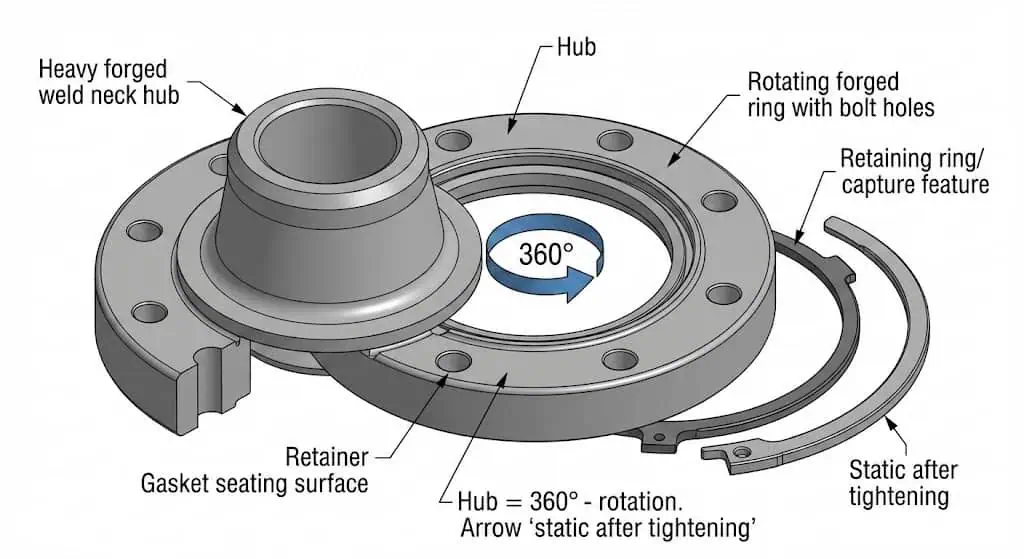
A swivel flange allows 360° rotation for precise bolt hole alignment during installation. In practice, the rotating ring is an assembly aid: you align the bolt pattern without twisting pipe spools, metal hoses, or fixed connectors, then you tighten the bolts and the connection becomes a normal static bolted joint. This is why swivel flanges are common in tie-ins, offshore/subsea work, and any location where pipe rotation is restricted.
Engineering note: treat the swivel flange as a bolted flange joint governed by the same fundamentals—pressure/temperature rating, flange facing, gasket selection, bolting material, and controlled tightening. On ASME-based projects, your dimensional/pressure framework typically references ASME B16.5 / B16.47 for flanges, ASME B16.20 for metallic gaskets, and ASME PCC-1 for assembly practices.
What is a swivel flange
Swivel flange definition
A swivel flange is a two-piece flange assembly designed for easy alignment during pipe installation.
This assembly consists of (1) a heavy forged welding hub (often weld neck) and (2) a rotating forged ring that carries the bolt hole pattern and mating face. A retainer keeps the ring captured on the hub. The key feature is that the ring can rotate freely before bolt-up, so you can match bolt holes without rotating the pipe spool.
Once bolts are tightened to the specified preload, the ring is clamped and does not provide operational “swivel” movement. If your system requires rotation during operation, that is typically a swivel joint/rotary union design—different component, different qualification basis.
Typical specification envelope (project-dependent):
- Pressure class and dimensions follow the project flange standard (commonly ASME B16.5 for NPS 1/2–24; large bore may follow ASME B16.47 for NPS 26–60).
- Facing options usually match standard practice: RF / FF / RTJ as required by service severity and the mating flange.
- Materials are selected by corrosion/temperature/service (for stainless, forged grades commonly fall under ASTM A182 families; bolts/nuts are specified separately).
Field example (alignment-controlled shutdown): On an offshore tie-in where the spool is fixed between guides, a swivel ring flange avoided cutting/re-welding a spool that was off by one bolt-hole pitch. The ring was rotated to match the mating flange, then bolts were installed using guide pins, and bolt-up proceeded normally.
Tip: A classic avoidable mistake is welding the hub to the pipe and then realizing the rotating ring was not installed/captured. Verify “ring on hub” before final weld-out.
Key working principle
The key working principle of a swivel flange is controlled rotation of the ring for bolt hole alignment.
Unlike a standard flange (bolt pattern fixed to the pipe end), the swivel ring lets the installer rotate only the bolt circle while the hub remains fixed to the pipe. This reduces assembly stress and avoids torsion on connected equipment such as metal hoses, expansion joints, and instrument tubing manifolds.
- Floating/swivel ring flanges allow bolt-hole alignment without twisting the connected component, which helps protect flexible connectors from torsional loading during assembly.
- Standard flanges have no alignment freedom; misalignment often forces “pipe movement,” which can introduce bending stress into the joint.
- After bolt-up, the joint is static; do not assume a swivel flange compensates for thermal expansion or vibration in operation—use proper supports, expansion devices, and stress analysis.
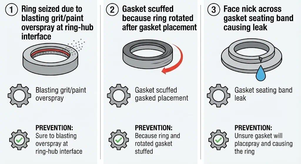
Field example (gasket damage prevention): A common leak cause is placing the gasket, then rotating the ring—this can scuff a soft gasket or displace a spiral-wound gasket. The fix is procedural: rotate the ring into final alignment using two guide studs first, then insert the gasket, then install bolts and tighten in sequence.
Sunhy’s swivel flange design is built around forged integrity and precision machining. From an engineering acceptance standpoint, you still confirm the mating dimensions, facing finish, and documentation (heat number traceability, mechanical tests, NDE where required) against the project specification.
Swivel Flange Types
Several types of swivel flange exist to meet different industrial needs.
In most projects, “type” is driven by hub attachment method (weld neck vs slip-on concept) and by material/service class. Always check the manufacturer drawing: swivel ring flanges are frequently configured as an assembly tailored to the mating flange standard and the end connection geometry.
The table below shows typical categories you will see in specifications and purchase descriptions:
| Type of Swivel Flange | Material | Application Type | Attachment Method |
|---|---|---|---|
| Carbon Steel Swivel Flange | Carbon Steel | General utility / non-corrosive service (per project spec) | Rotating ring for easy alignment; hub typically welded to pipe |
| Stainless Steel Swivel Flange | Stainless Steel | Corrosive media / offshore / chemical duty (grade verified by MTR) | Rotating ring for easy alignment; facing selected for gasket/service |
| Slip-on Swivel Flange | Various | General use where welding details allow slip-on style hub | Hub attaches per design; ring remains a captured rotating part |
| Weld Neck Swivel Flange | Various | Higher stress / fatigue-sensitive tie-ins and offshore spools | Hub welded directly to the pipe; ring rotates for bolt-up alignment |
The Swivel Ring Flange (SRF) stands out in offshore and subsea alignment work.
Teams use this configuration when bolt-hole alignment is difficult or impossible by rotating the spool—typical during subsea tie-ins or repair spools where movement is constrained. Key design features you should verify on the drawing include the retainer method, the ring capture detail, and the mating face compliance (RF/FF/RTJ) with the rest of the system.
- Simple rotation feature for bolt-hole alignment during installation.
- Retainer/capture feature to keep the ring in position on the hub (design varies by manufacturer).
- Accessible areas for cleaning (paint, grit, and weld spatter here can lock the ring and ruin the alignment benefit).
Field example (ring seizure): On a coastal chemical plant retrofit, a swivel ring would not rotate because blasting grit and coating overspray bridged the ring/hub interface. The corrective action was to mask the interface before coating, then clean and apply a controlled, service-compatible lubricant only where permitted by the assembly procedure.
Stainless steel swivel flange types, such as those produced by Sunhy, are typically chosen for corrosion resistance and traceable forging quality. Weld neck swivel flange types offer better stress distribution in higher-cycle service, while simpler configurations can suit general installations when the piping layout is accessible.
Tip: When “swivel flange” appears in a spec, ask one question early: is it only for assembly alignment, or does the system need rotation in operation? The answer changes the component selection and qualification approach.
Swivel flange components
Rotating ring and hub
The rotating ring and hub form the core of a swivel flange.
The hub is the structural element attached to the pipe end; the rotating ring carries the bolt holes and mates to the opposing flange face. The ring rotates around the hub prior to tightening, then becomes clamped after bolt-up.
What to inspect before assembly (practical checklist):
- Ring rotates smoothly by hand (no burrs, no coating bridges, no weld spatter in the interface).
- Retainer/capture feature is intact and correctly installed (verify per drawing).
- Bolt holes are clean and free of paint runs; chase threads on studs/nuts if required by procedure.
- Facing damage check: nicks, radial scratches across the gasket seating surface, and corrosion pitting in the gasket band are common leak starters.
Sunhy uses dual-certified 316/316L forgings for stainless swivel flange components. In engineering terms, dual certification can help procurement continuity, but acceptance still relies on the project-required MTR, PMI (if specified), and dimensional inspection.
- The hub provides a solid anchor for welding to the pipe.
- The rotating ring enables bolt hole alignment without moving the pipe.
- Both parts work together to reduce assembly-induced bending and rework.
Sealing surface and fasteners
The sealing surface and fasteners determine whether the joint stays leak-free.
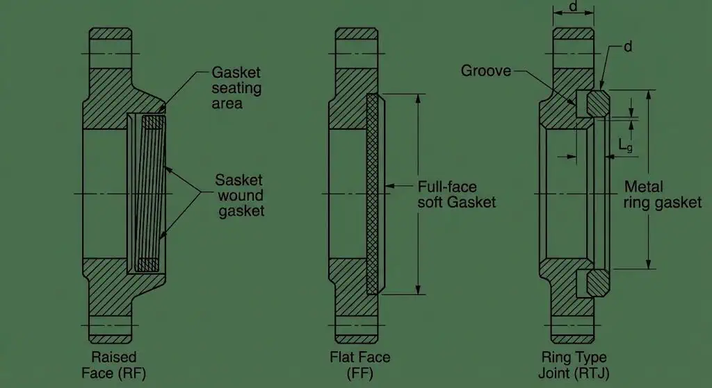
Facing type and surface finish must match the gasket design. For example, RF/FF faces commonly use controlled serrations/roughness for spiral-wound or soft gaskets, while RTJ faces require the correct ring groove geometry and metallic ring gasket selection.
Practical finish guidance (verify against your spec): For ASME-style RF faces, a typical finish range is 125–250 µin Ra (about 3–6 µm Ra). RTJ grooves commonly reference a much smoother finish requirement (often cited around 63 AARH). These values are widely used to support gasket seating, but your project specification and gasket vendor requirements govern the final acceptance.
- The sealing surface must match the gasket type for optimal sealing performance.
- Fasteners hold the assembly together and maintain gasket stress; bolt material/grade matters as much as torque value.
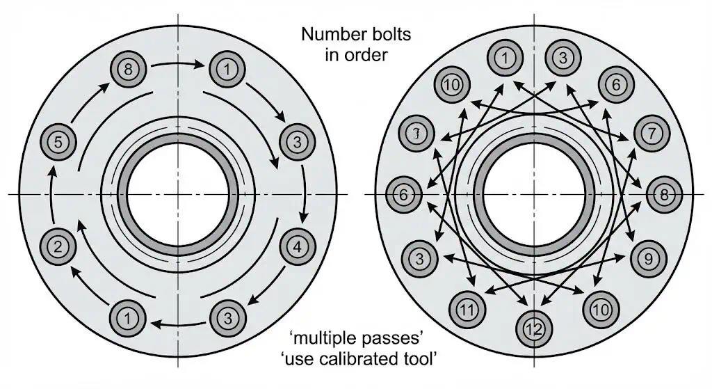
- Controlled tightening (sequence + passes + calibrated tooling) is a primary leak-prevention measure, not an afterthought.
Note: A swivel flange does not “fix” poor gasket selection or inconsistent bolt preload. Treat it like any other critical bolted flange joint—alignment gets easier, engineering discipline stays the same.
| Component | Function |
|---|---|
| Flange (Hub) | Provides the structural base, typically a forged hub attached to the pipe end. |
| Rotating joint (Ring) | Allows bolt-hole alignment by rotating around the hub prior to tightening. |
| Bearings/Bushings | In most swivel ring flange designs, rotation is achieved by controlled clearance and surface finish rather than rolling bearings; verify capture/retainer details on the drawing. |
| Sealing elements | Prevent leaks via the selected gasket system (RF/FF gasket, or RTJ metallic ring), matched to facing type and service. |
| Fasteners | Secure the joint and maintain gasket stress; stud/bolt and nut grades are specified separately from the flange forging. |
Sunhy’s swivel flange design combines forged manufacturing with machining control. For engineering acceptance, verify: (1) dimensions and facing per the applicable flange standard, (2) MTR/traceability, and (3) inspection/test requirements per the project ITP.
How does a swivel flange work
Installation and alignment
A swivel flange works by allowing the installer to rotate the flange ring for perfect bolt hole alignment.
During installation, the hub is attached to the pipe end (commonly welded). The rotating ring is then positioned so it can spin freely, and you rotate it until the bolt holes match the mating flange. This eliminates forced pipe movement and reduces assembly stress.
Common field trap to avoid: If the ring must be captured on the hub, install it before final hub-to-pipe welding. If you forget, correction often means cutting and rewelding—avoidable rework that also risks heat tint and distortion on the pipe end.
Tip: Use two guide studs (or alignment pins) to set the final bolt circle position first. Insert the gasket only after the ring is in final alignment to avoid scuffing or displacement.
Step-by-step installation and alignment process:
- Position the hub and weld it to the pipe end (per WPS/PQR and project spec).
- Slide the rotating ring onto the hub / confirm the capture/retainer detail is correct.
- Rotate the ring until the bolt holes align with the mating flange (use guide studs).
- Confirm that the flange surfaces are clean, smooth, and free of defects in the gasket seating area.
- Select the correct gasket material and thickness for the fluid, pressure, and temperature.
This method answers the question, how does a swivel flange work, by showing how rotation simplifies bolt-up while standard bolted-joint controls (cleanliness, facing, gasket, tightening) still determine sealing success.
Securing and sealing process
The swivel flange achieves a secure and leak-free seal through gasket control and disciplined bolt tightening.
After aligning the bolt holes, place the gasket and tighten bolts in a controlled, cross-pattern sequence using multiple passes. A calibrated torque wrench (or tensioning method where specified) helps achieve consistent bolt preload. Post-assembly leak checks and inspection are part of good practice—especially on critical fluids.
Industry standards for securing and sealing swivel flanges typically reference the same bolted joint principles used on standard flanges:
| Standard Aspect | Description |
|---|---|
| Material Compatibility | Confirm flange and bolting materials suit the operating environment; include sour service rules if H2S is present. |
| Size & Dimensions | Verify flange standard, NPS/DN, facing type, and bolt pattern match the mating flange and drawing. |
| Pressure & Temperature Ratings | Use the applicable flange standard pressure-temperature tables; class numbers are not “psi.” |
| Sealing Mechanisms | Match gasket type to facing (RF/FF gasket vs RTJ metallic ring) and finish requirements. |
| Ease of Installation | Use guide studs and keep the ring/hub interface clean so rotation remains smooth until bolt-up. |
| Certification & Standards | Request MTR/traceability and inspection records per the project ITP (dimensional, PMI, NDE where required). |
| Vendor Support & Warranty | Ensure supplier can provide drawings, tolerances, and material traceability to support engineering review. |
Checklist for securing and sealing:
- Select the appropriate gasket type and specification for service (pressure, temperature, media).
- Ensure gasket seating surfaces are clean and undamaged; do not “dress” faces unless the procedure allows it.
- Tighten bolts in a crisscross pattern using multiple passes; avoid single-pass “full torque” bolt-up.
- Use calibrated tools and follow the project tightening method (torque, tensioning, or turn-of-nut where specified).
- After the first controlled pressure/temperature cycle (as allowed by procedure), inspect for relaxation/leakage and re-verify bolt condition per site practice.
Sunhy’s swivel flange can be manufactured to common ASME/ASTM frameworks. Quality assurance for any supplier should be evidenced by documentation (MTR, heat number traceability), dimensional inspection records, and NDE/test results where required by the project.
The swivel flange design answers how does a swivel flange work by combining rotation for alignment with standard bolted-joint sealing practices. Alignment becomes easier; leak prevention still depends on correct facing, gasket choice, bolting, and tightening discipline.
Applications and advantages
Industry uses
Swivel flanges play a key role where bolt-hole alignment is the limiting factor during assembly.
They are most valuable when the connected pipe/spool cannot be rotated, or where rotating the connected equipment risks damage (hoses, expansion joints, instrument connections, subsea hardware).
- Oil and Gas / Offshore: Tie-ins, repair spools, constrained bolt-up locations, subsea alignment.
- Manufacturing and process plants: Retrofits where spools are fixed and bolt-hole orientation cannot be corrected by pipe rotation.
- Construction and hydraulics (project-specific): Where assemblies require alignment without twisting connected components (confirm the joint type—flange vs swivel joint).
- Agricultural and mobile equipment (project-specific): Similar alignment benefit on constrained assemblies.
- Petrochemical: Critical services where alignment errors translate into sealing risk and downtime.
- Robotics and medical devices (niche): Only where a true flanged pressure boundary exists; many systems use different connector families.
- Process Engineering: Skids and packaged units where space limits wrench access and alignment freedom.
For procurement and engineering, “where used” should always tie back to the joint need: alignment constraint + criticality + access. If those aren’t present, a standard flange often remains the simplest and most economical option.
Benefits over standard flanges
Swivel flanges offer practical benefits over standard flanges when alignment is constrained.
The main advantage is reduced assembly rework and reduced risk of forcing misalignment into the joint. That can improve sealing reliability because the bolts are not fighting a bent spool.
| Advantage | Description |
|---|---|
| Better Alignment | Swivel ring flanges allow rotational adjustment of the bolt hole pattern during installation, improving bolt fit-up. |
| Rotational Adjustment | The ring rotates around the hub so you can match the bolt circle without rotating the pipe spool. |
| Enhanced Leak Prevention | By avoiding forced misalignment, the joint is less likely to start with uneven gasket stress and uneven bolt load. |
Sunhy’s swivel flange stands out when the project requires controlled machining and traceable stainless forgings. For special layouts, confirm the drawing package early so bolt pattern, facing, and thickness match the mating flange and gasket system.
Note: A swivel flange improves fit-up efficiency. It is not a substitute for proper gasket selection, facing finish control, or disciplined tightening.
Selection Checklist
Standard/pressure rating
Choose a swivel flange with a pressure rating and standard basis that match your system requirements.
Pressure ratings must be verified against the applicable pressure-temperature tables for the correct material group. Avoid treating “Class” as “psi.” Use the governing standard and the project material group.
Rule of thumb for engineers: identify (1) governing flange standard, (2) material group/grade, (3) design temperature range, then confirm allowable rating. This prevents the common mismatch where a flange is “Class 300” but the material group or temperature makes the allowable pressure lower than expected.
| Class | Max Pressure (psi) | Typical Uses |
|---|---|---|
| 150 | ~285 (typical at low temperature range; verify by standard/material group) | General water, low-pressure steam |
| 300 | ~740 (typical at low temperature range; verify by standard/material group) | Oil, steam, higher pressure water |
| 600 | ~1,480 (typical at low temperature range; verify by standard/material group) | Chemical service, high-pressure lines |
| 900 | ~2,220 (typical at low temperature range; verify by standard/material group) | Refineries, power plants |
| 1500 | ~3,700 (typical at low temperature range; verify by standard/material group) | High-pressure steam & gas |
| 2500 | ~6,170 (typical at low temperature range; verify by standard/material group) | Extreme pressure, critical service |

Facing
Select the correct flange facing to ensure a reliable seal.
Facing type affects gasket seating stress, leak path geometry, and suitability for pressure/temperature. Always match facing to the mating flange and gasket standard.
- Raised face (RF): Concentrates gasket stress on a smaller area; common for process piping with spiral-wound or soft gaskets.
- Flat face (FF): Full-face contact; often used with full-face gaskets on certain flange materials and designs (verify system requirements).
- Ring-type joint (RTJ): Metal ring gasket seated in a groove; typical for higher pressure/temperature and critical sealing duties (groove and ring number must match).
Tip: Facing mismatch (RF to FF without correct gasket practice, or RTJ ring/groove mismatch) is a frequent root cause of persistent leaks.
Material
Pick a material that resists corrosion and matches your process fluid.
Material choice impacts corrosion, temperature capability, and sour service eligibility. Procurement should be backed by traceable MTRs and, where required, PMI/NDE. For H2S environments, material selection may be governed by sour service standards and project restrictions.
| Material | Corrosion Resistance Level |
|---|---|
| Stainless Steel | Excellent (grade and environment dependent) |
| Carbon Steel | Moderate (often needs corrosion allowance/coating/inhibitor) |
| Hastelloy | High (service-specific selection) |
| Inconel | High (service-specific selection) |
| Nickel Alloys | Very High (service-specific selection) |
| Titanium | Very High (chlorides and crevice conditions still matter) |
| Zirconium | Very High (specialty chemical duty) |
| Tantalum | Very High (specialty chemical duty) |
Environment
Consider the operating environment before selecting a swivel flange.
Temperature, pressure cycles, vibration sources, external corrosion, and media chemistry (chlorides, H2S, CO2, acids) all influence flange material and gasket/bolting selection. In offshore/subsea work, also consider cathodic protection interactions and crevice corrosion risk at gasket interfaces.
Note: Stainless selection is not “one size fits all.” If H2S is present, confirm sour service rules and project limits (e.g., ISO 15156 / NACE MR0175 where applicable).
Documentation
Verify that the flange meets all required standards and comes with proper documentation.
Documentation should include compliance certificates, pressure class/standard basis, material specifications, heat number traceability, and test reports. On critical systems, you may also require PMI, dimensional reports, and NDE records per the ITP.
| Checklist Item | Description |
|---|---|
| High-pressure rating | Confirmed by the governing standard’s pressure-temperature tables for the correct material group. |
| Corrosion resistance | Validated against the actual media chemistry and operating temperature range. |
| Material quality | Backed by MTR/traceability and tests required by the project specification. |
| Connection quality | Facing and bolt pattern match the mating flange; gasket selection matches facing and service. |
| Compliance with standards | Referenced standards are clearly stated (flange standard, gasket standard, bolting standard, assembly method). |
Tip: Always request drawings and an ITP summary from your supplier when the swivel flange is used in a constrained tie-in or critical service.
Limitations / Practical Notes
When it’s unnecessary
A swivel flange is unnecessary when pipe alignment is simple and space is ample.
If the pipe run can be rotated freely, or the bolt holes naturally align, standard flanges are usually simpler and lower cost. Low-pressure, non-critical services often do not justify the added parts and handling controls of a swivel ring assembly.
- Straight pipeline sections with no alignment challenges
- Low-pressure systems with minimal risk of leaks
- Installations where pipes and flanges can be freely rotated
Tip: Evaluate the fit-up risk first. If bolt-hole alignment is not a schedule driver, you may not benefit from a swivel flange.
Compatibility checks
Installers must perform compatibility checks before adding a swivel flange to an existing pipeline.
These checks prevent mismatches and confirm sealing compatibility. Use the drawing and the governing standard, not assumptions from “similar looking” flanges.
| Compatibility Check | Description |
|---|---|
| Specifications | Verify nominal size, pressure rating, facing type, and governing standard match system design. |
| Material Compatibility | Ensure flange/bolting/gasket materials match the media and temperature; check sour service requirements if applicable. |
| Alignment | Use guide studs and confirm bolt hole match before inserting the gasket and starting bolt-up. |
| Gasket Selection | Choose gasket type that matches the facing and finish; confirm thickness and inner/outer ring requirements where applicable. |
| Ongoing Maintenance | Inspect for leaks, bolt relaxation, corrosion at the gasket band, and any abnormal joint movement in supports. |
Installers should confirm that all components work together to maintain a leak-free connection. Proper checks reduce the risk of downtime and repeated tightening attempts that can damage the gasket or distort the joint.
Cost/lead time realities
Swivel flanges may increase project cost and lead time compared to standard flanges.
They include additional forged/machined parts and must maintain functional rotation during assembly. Custom bolt patterns, facing requirements, or NDE demands can extend lead time. The trade is often reduced installation rework and a lower chance of forced misalignment.
- Higher upfront cost due to multi-piece construction and machining controls
- Longer lead times for custom drawings, special materials, or enhanced inspection
- Potential savings in installation time and reduced fit-up rework
Note: The long-term value is usually in fit-up reliability and reduced rework—not in “absorbing vibration” or “taking thermal expansion” in operation.
A swivel flange enables fast, precise alignment and secure sealing when bolt-hole alignment is the limiting factor.
This design supports easier assembly and reduces forced fit-up stress, which can improve gasket seating conditions. Sunhy Stainless Steel Flanges can be supplied with traceable stainless forgings and machining controls suitable for demanding environments when specified correctly.
Choosing a swivel flange is an engineering decision about installation constraints. It does not replace expansion joints, vibration isolation, or proper piping supports.
| Benefit | Description | Example |
|---|---|---|
| Fit-up stress reduction | Avoids forcing misalignment into the joint | Retrofit tie-in where the spool cannot be rotated |
| Controlled bolt-up | Improves ability to use guide studs and tightening sequence | Critical service where gasket stress uniformity matters |
| Installation efficiency | Faster alignment in constrained access areas | Offshore deck piping with limited maneuvering room |
| Maintenance planning | Reduces repeated disassembly caused by alignment errors | Turnaround work with strict schedule windows |
Sunhy’s products can be specified to meet required standards and documentation. For offshore/subsea work, add clear requirements for materials, facing, bolting, and inspection in the purchase specification so alignment convenience does not come at the cost of sealing reliability.
FAQ
What makes a swivel flange different from a standard flange?
A swivel flange allows 360° rotation of the ring for bolt alignment during assembly.
The hub stays fixed to the pipe while the ring rotates to match bolt holes. After bolts are tightened, the joint is clamped and behaves like a standard bolted flange connection.
Where are swivel flanges most commonly used?
Swivel flanges are most common where alignment is constrained and the service is critical.
Typical use cases include offshore/subsea tie-ins, constrained retrofits in process plants, and assemblies where rotating the pipe spool would twist or damage connected equipment.
How does Sunhy ensure the quality of its swivel flanges?
Quality should be demonstrated through traceable materials and inspection records.
For stainless swivel flanges, verify MTR/heat number traceability, dimensional inspection, and any specified NDE (e.g., ultrasonic testing) per the project ITP. Manufacturing claims matter less than documented evidence that the supplied flange matches the drawing and specification.
Can swivel flanges be customized for special projects?
Yes—customization is common, but it must be controlled by drawings and standards references.
Clients may request unique sizes, special bolt patterns, facing finishes, or enhanced inspection. Provide mating flange details and service conditions early so the rotating ring, retainer, and facing system are engineered correctly.
What maintenance do swivel flanges require?
Maintain them like any other bolted flange joint: inspect for leaks, corrosion, and bolt condition.
Focus on gasket-band corrosion, bolt relaxation indicators, and any abnormal movement in supports. If the system experiences thermal cycles, follow site procedure for post-cycle inspection and bolt condition verification. The “swivel” feature is for assembly; it is not a routine operational movement mechanism.