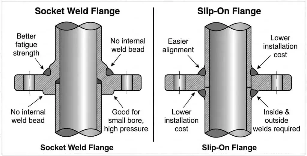
The main difference between socket weld flanges and slip on flanges lies in how the pipe is seated and welded—this directly affects fatigue behavior, weld-related leak risk, and how sensitive the joint is to fit-up errors.
In practice, the right choice depends on pressure class, pipe size (especially small-bore), vibration/cyclic loading, corrosion risk, fabrication quality control, and maintenance philosophy. This page is written as a selection and comparison guide for engineers, buyers, and maintenance teams. If you need product-specific dimensions and purchasing details, see our Socket Weld Flanges (SW), Slip On Flanges (SO), and Weld Neck Flanges (WN) product pages.
If your project uses ASME flange systems, dimensional patterns and rating classes are commonly governed by ASME B16.5 flange dimensions and drilling patterns. For official standard scope references, see the ASME B16.5 standard page.
Procurement note: Treat this as an engineering decision, not a “cheapest flange” decision. The hidden cost is usually rework: face distortion, hydrotest leakage, misalignment, or vibration-driven failures after startup.
Quick answer (typical selection tendency; final decision = code + piping class + load case):
| Flange Type | Typical Strengths | Where It Fits Best |
|---|---|---|
| Slip-On (SO) | Fast fit-up, economical fabrication, broad use in utility/general piping | Stable-load services where weld distortion and vibration are controlled |
| Socket Weld (SW) | Compact small-bore joint, repeatable fit-up location, common in higher-pressure small-bore service | Small-bore service where piping class allows SW and workmanship/support controls are strong |
| Weld Neck (WN) | Better stress transition and load transfer, often favored in critical duty | Severe cyclic, high vibration, high consequence, or stricter piping classes |
Need a product-specific breakdown? Review Socket Weld Flange specifications, Slip On Flange specifications, and Flange Standards Overview before purchase release.
Socket weld flange overview (SW)
Design and fit-up logic
Socket weld flanges are designed so the pipe OD nests into a counterbore (“socket”), and the pressure boundary is completed with an external fillet weld.
The socket helps locate the pipe during fit-up, which is why SW flanges are common in small-bore work. In service, performance depends less on the socket shape itself and more on fit-up discipline, weld profile quality, support spacing, and vibration/thermal cycling control.
Procurement note (common field mismatch): Ensure the PO clearly states NPS, class, facing (RF/FF/RTJ where applicable), bore, and the socket weld end type. If you are ordering for repeat skids or modular builds, standardize your datasheet language—see how to order socket weld flanges for a practical checklist.
| Feature | Description |
|---|---|
| Joint Type | Socket Weld (SW) flange |
| Geometry | Socket/counterbore locates pipe before external fillet weld |
| Typical Use | Small-bore service where compact geometry and repeatable fit-up matter |
| Key Risk If Misapplied | Vibration fatigue, crevice/corrosion concerns in some wet services, poor fit-up/WPS control |
How socket weld flanges work in real systems
Socket weld flanges create a welded pressure boundary after the pipe is seated in the socket and welded externally. Many project procedures require a small stand-off (gap) after full insertion before welding to reduce shrinkage stress and improve weld consistency; the exact value is controlled by the applicable code/specification and qualified WPS.

- Fit-up control: seat the pipe, apply the required stand-off per WPS/spec, then tack and re-check face alignment.
- Weld profile control: over/under-welding and poor heat input control can reduce fatigue margin and distort alignment.
- Crevice awareness: the socket region can be problematic in aggressive wet/chloride-bearing services if chemistry and maintenance are not controlled.
- Bolted face control: flange facing condition and bolting method still govern gasket sealing performance after welding.
Field example (common shutdown issue): A small-bore SW line passes hydrotest but leaks after warm-up. In many cases, the root cause is not “bad gasket quality,” but a combination of fit-up/stand-off error, face misalignment, and thermal movement unloading the gasket.
Where engineers use caution
Socket weld flanges are often a strong option in small-bore service, but they are not a universal upgrade. Engineers get cautious in vibration-prone areas, severe thermal cycling, and wet corrosive services where crevice conditions may accelerate corrosion.
| Limitation Type | Description |
|---|---|
| Fatigue Cracking | Small-bore vibration + cyclic pressure/temperature can crack at the weld toe if supports are poor. |
| Fit-up / WPS Issues | Poor stand-off control, alignment, or weld profile can reduce reliability and increase leak risk. |
| Face/Gasket Mismatch | Wrong facing or gasket type can cause leakage independent of flange type. |
| Crevice / Corrosion Risk | Socket region and poor drainage can trap deposits in some wet services. |
For broader SW product data, materials, and ordering details, see Socket Weld Flanges (SW) specifications.
Slip-on flange overview (SO)
Design and fit-up logic
A slip on flange slides over the pipe OD and is secured by fillet welds (typically inside + outside per WPS/spec).
This geometry makes slip-on flanges fast to fit and economical in many utility and general services. The tradeoff is that the joint is highly dependent on weld sequence, weld profile, and flange-face distortion control.
Tip: Slip on flanges look forgiving during fit-up, but many startup leaks are caused by weld sequence distortion, poor alignment, or uneven bolt load—not the gasket alone.
How slip on flanges work in real systems
The slip-on joint is built by setting pipe projection and applying controlled fillet welds. The engineering challenge is not simply “making the weld”; it is preserving face alignment and gasket seating quality after welding.
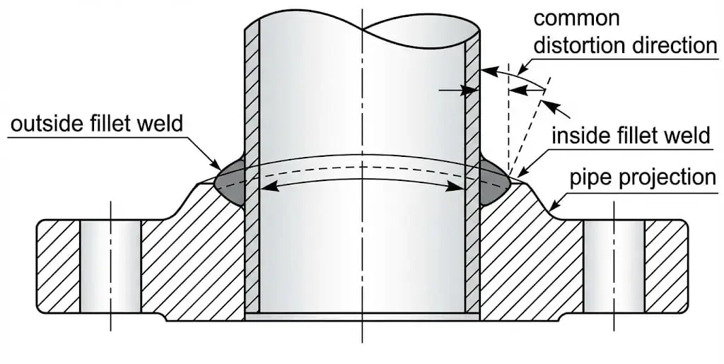
- Projection control: set pipe projection per WPS/spec to avoid poor inside fillet geometry or crevice issues.
- Distortion control: weld sequence and heat input can rotate/pull the flange face; verify face parallelism before bolting.
- Weld size control: under-sized welds reduce margin; excessive welding can distort the face and increase leak risk.
- Bolted face protection: keep gasket seating surfaces free from arc strikes and grinding damage.
Slip-on flanges are widely used because they are fast to fabricate and economical, especially where external loads are stable and inspection access is good. For sizes/classes/materials, see Slip On Flanges (SO) specifications.
Socket weld flange vs slip on flange: comparison
Installation process
Socket weld flanges demand tighter fit-up discipline at the socket region; slip on flanges generally install faster but require consistent control of weld sequence and face distortion.
Neither joint type “wins” if the flange face is out of parallel or if piping is forced into alignment during bolt-up.
- Socket weld flange: seat pipe, set stand-off per WPS/spec, tack, verify squareness/parallelism, then apply external fillet weld with controlled heat input.
- Slip on flange: slide into position, set projection per WPS/spec, tack evenly, then weld in a sequence that limits flange-face distortion.
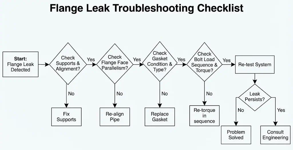
Field check before blaming the gasket: (1) flange face parallelism, (2) support/vibration condition, and (3) bolt load uniformity.
Strength and performance under real loads
Both socket weld and slip on flanges can meet code dimensions and ratings, but they respond differently to vibration and bending loads.
In fatigue-driven systems, weld profile quality, support spacing, and cyclic load magnitude often dominate performance more than the flange label.
| Flange Type | Performance Character | Where It Performs Well |
|---|---|---|
| Socket Weld Flange | Compact joint; sensitive to fit-up and weld quality at the socket region | Small-bore service when vibration/corrosion risks are managed |
| Slip On Flange | Economical and fast; relies on consistent fillet weld quality and face control | Stable-load utility/general services with good QC and support control |
| Weld Neck Flange (reference) | Better stress transition and load transfer in many severe services | Critical duty / higher cyclic or vibration loads when specified |
- If the line is near rotating equipment, evaluate vibration and cyclic bending first—poor supports will cause leaks regardless of flange type.
- If the service is wet and chloride-bearing, review crevice/corrosion risk at weld regions and confirm cleaning/passivation expectations for stainless systems.
Pressure rating and service restrictions
Pressure capability is governed by flange rating and pressure-temperature tables, then constrained by service rules in the piping class.
Both socket weld and slip on flanges are available in ASME pressure classes, but many owner specifications restrict where they may be used in severe cyclic, high-vibration, or hazardous services.
- High pressure + small-bore: SW is commonly selected where compact geometry and access favor socket weld construction and the piping class permits it.
- Stable-load utilities: SO is commonly selected where speed and cost matter and vibration is controlled.
- Severe cyclic/vibration: many piping classes move to higher-integrity designs (often weld neck flanges) rather than trying to “make SO/SW work” in the wrong location.
Cost, maintenance, and hidden rework risk
Slip on flanges are usually lower unit cost and faster in repetitive fabrication work; socket weld flanges can reduce fit-up variability in compact small-bore installations when procedures are standardized.
The hidden cost in both cases is rework: face distortion, hydrotest leaks, alignment correction, gasket replacement, and downtime.
| Factor | Slip On Flange (SO) | Socket Weld Flange (SW) |
|---|---|---|
| Installed Cost Driver | Fabrication speed vs weld distortion rework | Fit-up discipline / inspection expectation vs repeatability benefit |
| Maintenance Attention | Check weld integrity, face distortion, bolt-up quality | Check socket-region condition, alignment/supports, weld quality |
| Typical Leak Driver | Uneven bolt load, face distortion, misalignment | Fit-up/stand-off issue, vibration fatigue, face load loss after thermal movement |
Bolted joint assembly discipline matters for both types. Many sites reference procedures based on ASME PCC-1 (Pressure Boundary Bolted Flange Joint Assembly) or equivalent owner standards.
How to choose the right flange
Selection criteria (what actually prevents startup leaks)
Prioritize pressure-temperature requirements, external loads, corrosion risk, and installation quality control when choosing between socket weld and slip on flanges.
These criteria prevent most “mystery leaks” seen during hydrotest and early operation:
- Pressure/temperature basis: confirm the controlling pressure-temperature table, standard scope, and project piping class restrictions.
- External loads and vibration: if the flange is near rotating equipment or on an unsupported span, assume cyclic load risk until proven otherwise.
- Corrosion/crevice risk: review service chemistry, wet/dry cycles, deposits, and stainless surface condition expectations.
- Facing and gasket strategy: RF/FF selection, gasket type, and bolt load method must match.
- Repeatability of fabrication: choose the joint style your shop/site can execute consistently without “hero work.”
Quick decision table (typical tendency; final decision = spec + load case + QC capability):
| Condition at the Joint | More Typical Choice | Why |
|---|---|---|
| Small-bore, higher-pressure, compact access | Socket Weld Flange | Compact geometry and repeatable fit-up when WPS/stand-off is controlled |
| Utility service, stable supports, large quantity | Slip On Flange | Fast fabrication and economical installation |
| Strong vibration/cyclic bending or critical duty | Weld Neck Flange (often) | Better stress transition and load transfer; commonly favored in stricter piping classes |
Expert selection habit: Decide the support/vibration strategy first. Many flange problems are structural-load problems in disguise.
Mistakes to avoid (common field failure patterns)
Most field failures come from predictable mistakes—avoid these and leak rates drop quickly.
- Using flange rating as the only decision input: a “rated” flange can still be the wrong choice in severe cyclic/vibration locations.
- Wrong gasket/facing pairing: RF/FF mismatch or wrong gasket style causes leakage under thermal transients.
- Skipping controlled bolt-up: uneven bolt load is a top leak driver; use controlled sequence/lubrication and verify procedure compliance.
- Forcing alignment at bolt-up: pulling piping into place with bolts preloads the joint and reduces gasket compression uniformity.
Field examples (problem → likely cause → prevention):
| Example | What Happened | Likely Cause | Fix / Prevention |
|---|---|---|---|
| Slip-on flange leaks during hydrotest on a utility header | Weeping at one quadrant after tightening | Face distortion from weld sequence + uneven bolt load | Check face flatness/parallelism, correct as required, reassemble with controlled bolt-up and lubrication practice |
| Socket weld flange leak appears after warm-up | Leak starts after thermal cycle | Fit-up/stand-off issue, face misalignment, or thermal movement unloading gasket | Verify stand-off practice per WPS, check supports/guides, confirm flange face condition and bolting method |
Field lessons, research examples, and authority references
Why experienced teams treat flange choice as a system decision
Experienced piping teams do not treat flange selection as a stand-alone component choice. They treat it as a system decision: flange type + weld execution + supports + alignment + gasket + bolt-up procedure + maintenance access.
- Pipework integrity is a recurring process-safety theme: HSE guidance on refinery pipework integrity highlights the importance of systematic inspection and integrity controls for pipework systems, not just individual components. See HSE pipework integrity guidance.
- Line opening / flange disassembly incidents show procedure matters as much as hardware: Public incident summaries from the U.S. Chemical Safety Board include flange-opening and line-opening events where isolation, depressuring, and work control failures caused serious consequences. See CSB Incident Reports Volume One.
- Bolted flange reliability depends on assembly discipline: ASME PCC-1 is widely referenced in industry for bolted flange joint assembly procedure development and quality control. See the ASME PCC-1 standard page.
Practical takeaway: If you want fewer leaks, stop treating the flange, gasket, weld, and supports as separate checklists. They are one reliability system.
FAQ
What is the main difference between socket weld and slip on flanges?
Socket weld flanges seat the pipe into a socket and use an external fillet weld; slip on flanges slide over the pipe and typically use fillet welds per WPS/spec.
Socket weld flanges are commonly selected for compact small-bore work where fit-up repeatability matters. Slip on flanges are commonly selected for utility and general services where speed and cost are priorities and vibration is controlled.
Can you use slip on flanges for high-pressure applications?
Slip on flanges can be supplied in ASME pressure classes, but many piping classes restrict where they can be used.
In high-pressure service with vibration, thermal cycling, or critical duty, many owner specifications favor higher-integrity joints (often weld neck) and stricter inspection requirements. Always follow the piping class, code, and weld/NDE plan for the specific line.
When is a socket weld flange usually preferred?
Socket weld flanges are commonly preferred in small-bore service where compact geometry and repeatable fit-up are important and the piping class allows SW construction.
They are not automatically the best choice in vibration-prone or crevice-sensitive services; support design, chemistry, and fabrication quality still control reliability.
What are the most common causes of flange leakage after commissioning?
Most leaks come from flange face distortion, misalignment/pipe spring, wrong gasket/facing pairing, or uneven bolt load—not the flange type alone.
Before replacing the gasket, check face parallelism, supports/thermal movement control, and bolt-up procedure compliance.
When should you choose a weld neck flange instead?
Weld neck flanges are often selected when the service is severe, cyclic, vibration-prone, or high consequence and the piping class favors higher-integrity butt-welded joints.
The final decision should follow the load case, service risk, code/specification, and inspection plan—not a generic ranking chart.
Does flange class alone determine suitability?
No. Flange class is only one part of the decision.
Real-world suitability depends on pressure-temperature conditions, piping class restrictions, external loads/vibration, corrosion environment, weld quality, gasket/facing compatibility, and bolt-up discipline.
Related Technical Resources
Continue your engineering review with these related product pages and technical guides. Use these links to confirm dimensions, standards, ordering details, and alternative flange choices before finalizing your piping class selection.
| Resource Type | Recommended Link | Why It Helps |
|---|---|---|
| Product Specifications | Socket Weld Flanges (SW) Specifications | Review SW dimensions, materials, and product scope for small-bore applications. |
| Product Specifications | Slip-On Flanges (SO) Specifications | Check SO sizes, facing options, and where slip-on flanges fit best in utility/general service. |
| Alternative for Severe Service | Weld Neck Flanges (WN) | Useful when vibration, cyclic loading, or critical-duty service may favor a higher-integrity joint. |
| Standards | Flange Standards Overview (ASME / DIN / EN) | Confirm governing standards, rating systems, and compatibility requirements. |
| ASME Reference | What ASME B16.5 Means for Pipe Flanges and Flange Fittings | Quick internal reference for ASME B16.5 scope, classes, and engineering interpretation. |
| Ordering Checklist | How to Order Socket Weld Flanges | Useful for RFQ and PO wording (NPS, class, facing, bore, material, and documentation). |
| Flange Taxonomy | Different Types of Flanges for Piping | Helpful if your internal team is comparing multiple flange types beyond SO vs SW. |
| Installation / Leak Prevention | Threaded Flange Installation Guide (NPT vs BSPT, Leak Prevention & Troubleshooting) | Useful for teams comparing welded vs non-welded flange connection strategies in maintenance planning. |
Selection reminder: Final flange selection should be based on the full system condition—pressure/temperature, external loads, vibration, corrosion risk, fabrication quality control, gasket/facing compatibility, and the project piping class.