Plate Flat Face (FF) Flanges - ASME B16.5
Plate Flat Face (FF) flanges are a foundational component for low-pressure piping systems, designed for applications where a full-face soft gasket is required.
As a specialist manufacturer of industrial flanges, Sunhyings produces a comprehensive range of Plate FF Flanges engineered to meet strict ASME B16.5 standards. Our production capabilities cover all standard specifications, including Class 150 and Class 300, in materials such as Stainless Steel (SS304/316L).
Types of Plate Flat Face Flanges We Supply
 Stainless Steel Flanges
By Design Type
By Standard & Class
Advanced Materials

4-Bolt Stainless Steel Plate Flange, PN16 Flat Face (FF)

4-Bolt SS304 Stainless Steel Plate Flange, FF

4-Bolt Stainless Steel Plate Flange, ASME B16.5 Class 150 FF


4-Bolt Stainless Steel Plate Flange, DIN Standard FF

8-Bolt SS316L Plate Flange, PN16 Flat Face (FF)

8-Bolt Industrial Stainless Steel Plate Flange, FF

8-Bolt Stainless Steel Plate Flange, JIS 10K FF
Precision Forged Plate FF Flanges Supplier
In low-pressure piping systems, reliable sealing is critical. Sunhyings’ Plate FF Flanges are designed specifically for such applications. Their flat-face design is intended for use with full-face gaskets, providing a cost-effective and secure sealing solution.
As a professional manufacturer, we ensure that every flange meets the precise tolerances of ASME B16.5. We specialize in SS304/316L stainless steel and maintain a stock of Class 150 and Class 300 to ensure rapid response and superior quality for your projects.
Nominal Pipe Size (NPS / DN):
NPS: 1/2″ to 48″
DN (Metric): DN15 to DN2000 (Covers small to large pipelines)
Pressure Rating (Class / PN):
ASME Class: 150, 300, 400, 600, 900, 1500, 2500
Metric (PN): PN6, PN10, PN16, PN25, PN40 (Indicates pressure capacity)
Joint/Facing Type:
Flat Face (FF), Raised Face (RF) ,Ring Type Joint (RTJ)
What is a Plate / Flat Face Flanges
Plate flanges are a highly cost-effective connection solution, as they are cut directly from sheet steel rather than forged. This manufacturing process makes them ideal for low-pressure, non-critical systems such as water treatment and HVAC. During installation, they are fitted over the pipe and secured by fillet welds on both the inner and outer sides.
Their “flat face” (FF) characteristic means that the entire sealing surface of the flange is completely flat. This design requires the use of a full-face gasket, whose key function is to protect the connected, fragile equipment (such as cast iron valves or pumps). By evenly distributing bolt pressure across the entire surface, FF flanges effectively prevent flange breakage due to uneven stress.
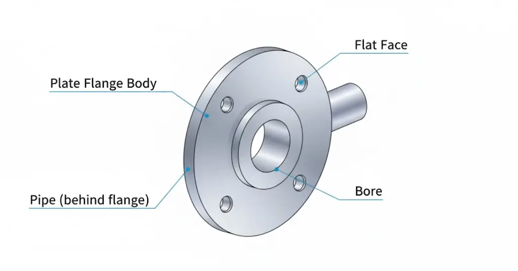
Plate / Flat Face Flanges Specifications
Multi-Standard Versatility
Our Plate Flanges are engineered for global adaptability, fully compliant with EN 1092-1 Type 01 (European) and JIS B2220 SOP (Japanese/Asian) standards.
Legacy Support: Fully compatible with and often used as a direct replacement for the classic DIN 2576 (PN10/PN16) standard.
Waterworks Application: Also available in AWWA C207 and BS 10 configurations for municipal water and low-pressure utility lines.
Design & Engineering
Machined directly from high-quality steel plate, offering a robust yet cost-effective solution for non-critical pressure applications.
Flat Face (FF) Design: Ideal for mating with brittle materials (such as cast iron valves) or where full-face gaskets are required to prevent flange rotation.
Profile: Features a low-profile design without a hub, reducing weight and simplifying alignment in tight spaces compared to Slip-On flanges.
Dimensional Reference
Refer to the schematic diagram to ensure correct fitment:
D: Outside Diameter
K: Bolt Circle Diameter (Crucial for mating compatibility)
B: Inside Diameter (Pipe Clearance)
C: Flange Thickness
Technical Note: Plate flanges are designed for low-pressure systems. For high-stress or cyclic pressure environments, please consider our Forged Slip-On or Weld Neck flanges.
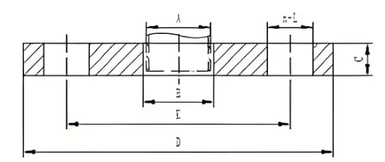
Plate Flanges (Flat Face, PN/10K/AWWA) Dimensions
Standards: EN 1092-1 Type 01, JIS B2220 SOP, AWWA C207, BS 10EN 1092-1 Type 01 (PN16) - Metric Plate
Commonly referred to as DIN 2576 (legacy standard).
| DN (Size) |
Outside Dia (D) (mm) |
Inside Dia (B) (Pipe Clearance) |
Thickness (b) (mm) |
Bolt Circle (K) (mm) |
Holes (Qty) |
Bolt (Metric) |
|---|---|---|---|---|---|---|
| DN15 | 95 | 22.0 | 14 | 65 | 4 | M12 |
| DN20 | 105 | 27.5 | 16 | 75 | 4 | M12 |
| DN25 | 115 | 34.5 | 16 | 85 | 4 | M12 |
| DN40 | 150 | 49.5 | 18 | 110 | 4 | M16 |
| DN50 | 165 | 61.5 | 20 | 125 | 4 | M16 |
| DN80 | 200 | 90.5 | 20 | 160 | 8 | M16 |
| DN100 | 220 | 116.0 | 22 | 180 | 8 | M16 |
| DN150 | 285 | 170.5 | 24 | 240 | 8 | M20 |
| DN200 | 340 | 221.5 | 26 | 295 | 12 | M20 |
JIS B2220 10K SOP (Slip On Plate)
| Size (DN) |
Outside Dia (mm) |
Inside Dia (mm) |
Thickness (mm) |
Bolt Circle (mm) |
Holes (Qty) |
Bolt (Metric) |
|---|---|---|---|---|---|---|
| 15A | 95 | 22.2 | 12 | 70 | 4 | M15 |
| 25A | 125 | 34.5 | 14 | 90 | 4 | M16 |
| 40A | 140 | 49.1 | 16 | 105 | 4 | M16 |
| 50A | 155 | 61.1 | 16 | 120 | 4 | M16 |
| 80A | 185 | 90.0 | 18 | 150 | 8 | M16 |
| 100A | 210 | 115.4 | 18 | 175 | 8 | M16 |
| 150A | 280 | 166.6 | 22 | 240 | 8 | M20 |
| 200A | 330 | 218.0 | 22 | 290 | 12 | M20 |
AWWA C207 Class D (150 psi)
The US standard for waterworks plate flanges (Flat Face).
| NPS (Size) |
OD (Inch) |
ID (Inch) |
Thickness (Inch) |
Bolt Circle (Inch) |
Holes (Qty) |
Bolt (Inch) |
|---|---|---|---|---|---|---|
| 4" | 9.00 | 4.57 | 0.625 | 7.50 | 8 | 5/8" |
| 6" | 11.00 | 6.72 | 0.688 | 9.50 | 8 | 3/4" |
| 8" | 13.50 | 8.72 | 0.688 | 11.75 | 8 | 3/4" |
| 10" | 16.00 | 10.88 | 0.688 | 14.25 | 12 | 7/8" |
| 12" | 19.00 | 12.88 | 0.812 | 17.00 | 12 | 7/8" |
BS 10 Table E (Historic Plate)
| NPS (Size) |
Outside Dia (D) (mm) |
Thickness (mm) |
Bolt Circle (PCD) (mm) |
Holes (Qty) |
Bolt Dia (Inch) |
|---|---|---|---|---|---|
| 1" | 114.3 | 7.1 | 82.6 | 4 | 1/2" |
| 2" | 152.4 | 8.7 | 114.3 | 4 | 5/8" |
| 3" | 184.2 | 11.1 | 146.1 | 4 | 5/8" |
| 4" | 215.9 | 12.7 | 177.8 | 8 | 5/8" |
| 6" | 279.4 | 17.5 | 235.0 | 8 | 3/4" |
| 8" | 336.6 | 19.0 | 292.1 | 8 | 3/4" |
Looking for SANS 1123 or Table D dimensions?
Download Full BS/SABS TableTech Note: Plate (Type 01) vs Slip On (Type 12)
- Structure: Flat disc, no hub.
- Welding: Double fillet weld (inside & outside).
- Use Case: Low pressure, water pipelines, cost-critical projects.
- Structure: Has a tapered hub for reinforcement.
- Pressure: Suitable for higher pressures (up to Class 1500).
- Use Case: Oil & Gas, Process Piping, ASME B16.5 standards.
Not sure which flange type fits your pipeline? Our engineers can balance stress, pressure and cost for your specific project.
When and Where to Use Plate / Flat Face Flanges
1. Economy Applications (Plate): Since the flange is directly cut from a steel plate, it is the most cost-effective choice for low-pressure, non-critical systems (such as Class 150/PN16 and below).
Typical Applications: Building water treatment, HVAC (Heating, Ventilation, and Air Conditioning) systems, drainage lines, and general industrial air ducts.
2. Protecting Brittle Equipment (Flat Face): This is the most important rule of use. When your piping needs to connect to flanges made of brittle materials, a flat face (FF) flange must be used.
Typical Applications: Connecting cast iron valves, pumps, plastic flanges, or fiberglass tanks. The flat face (FF) design, combined with a full-face gasket, distributes bolt pressure evenly, preventing the brittle flange from cracking due to uneven stress.
Plate / Flat Face Flanges Installation and Welding Best Practices
Welding Best Practice
Always use two fillet welds (dual-sided welding).
1. Outside Weld: Weld the flange hub to the outer pipe wall.
2. Inside Weld: Weld the flange bore to the pipe end face.
Note: We strongly recommend always using both welds. This provides maximum strength and prevents crevice corrosion between the flange and pipe.
Installation Steps
Preparation: Ensure the Flat Face (FF) and pipe end are clean, dry, and free of rust or scratches.
Positioning:
Slide the flange onto the pipe.
Crucial: Set the pipe end back ~3mm (1/8″) from the flange’s inner face. This creates space for the internal fillet weld.
Alignment: Square the flange face 90° (perpendicular) to the pipe and fix it with tack welds.
Welding: Complete the full welding (outside first, then inside) using a multi-pass technique if needed. Allow to cool.
Assembly:
Insert the Full-Face (FF) Gasket. (Do NOT use a raised-face gasket).
Tighten bolts gradually using a star pattern (criss-cross) to ensure even pressure.
Required Mating Components
To ensure a safe, leak-free installation of your Plate Flat Face (FF) Flanges, the correct mating components are required. Please ensure you source the following items:
Gasket Type: Full-Face Gasket A gasket that covers the entire flange face (conforming to ASME B16.21) is mandatory. Common materials include Non-Asbestos, EPDM, or Rubber, depending on your service media.
Warning: DO NOT use a Raised Face (RF) gasket. This will cause a sealing failure and potential damage.
Bolting: Flange Bolt & Nut Kits Standard stud bolts and nuts are required to complete the assembly. Common materials include Carbon Steel (A193 B7 / A194 2H) or Stainless Steel (SS304 / SS316).
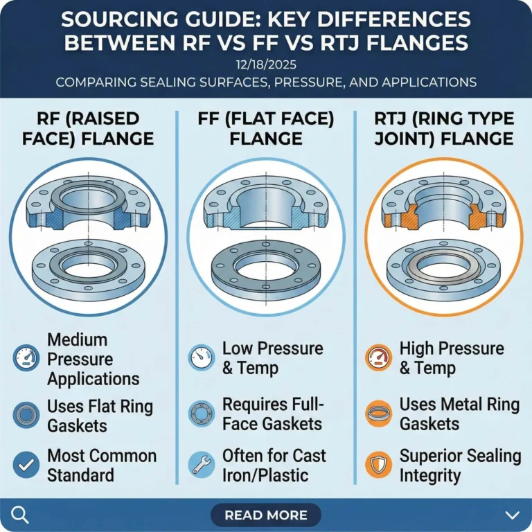
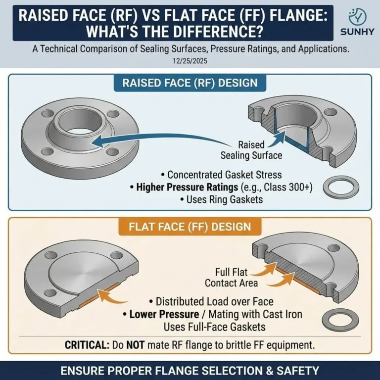
Flat Face (FF) vs. Raised Face (RF): Key Differences
Understanding the distinction is critical for proper selection. While a Raised Face (RF) flange has a small raised surface for sealing, an FF flange is completely flat. This fundamental design difference dictates their use:
- Gasket Type: FF flanges require a soft, full-face gasket (like rubber or non-asbestos) that covers the entire flange surface.
- Pressure Class: RF flanges are used for higher-pressure/temperature applications (typically Class 300 and up) as they concentrate pressure on a smaller gasket area.
- Mating Flanges: Crucial Warning: Never bolt a Raised Face (RF) flange to a Flat Face (FF) flange. The high-point pressure from the RF flange will crack the FF flange.
FAQ
can you connect a raised face flange to flat face
No. This is a hazardous practice and explicitly prohibited by piping codes.
According to industry standards like ASME B31.1, a Raised Face (RF) flange must never be bolted directly to a Flat Face (FF) flange , especially when the FF flange is made of a brittle material like cast iron.
Failure Mode: Mating these two types creates an unsupported gap between the flanges. When the bolts are tightened, the RF flange’s raised ring concentrates all the force on a small area of the FF flange. This acts as a prying force, creating a bending moment that will fracture or crack the brittle flat face flange.
Correct Procedure: The only code-compliant solution (e.g., when connecting a new steel pipe to an old cast iron valve) is to machine off (remove) the raised face from the steel flange, converting it into a flat face flange. After machining, a full-face gasket must be used for the connection.
why use flat face flanges
The primary reason to use a Flat Face (FF) flange is to prevent the cracking or fracture of brittle flange materials when bolts are tightened.
Engineering Principle (Why): The flat face design is intended to prevent a bending moment by distributing the bolt load evenly across the entire gasket surface. This even pressure is critical for materials with low ductility, such as cast iron, PVC, or fiberglass (GRP).
Failure Prevention: A Raised Face (RF) flange, by contrast, concentrates all the pressure on a small, raised ring. This concentrated load would create a bending force and stress concentration that could easily crack or break a brittle flange.
Application (When): Because of this design, FF flanges are used in low-pressure and low-temperature systems. Common applications include water treatment plants , HVAC systems , pump suctions , and fire protection lines. They are most common in Class 125 and Class 150 pressure ratings.
can you use spiral wound gasket on flat face flange
It is not recommended, unless you use a specially designed “Low Stress” version.
Standard Spiral Wound Gaskets (No): A standard spiral wound gasket (SWG) should not be used on a typical flat face flange. SWGs are semi-metallic gaskets that require very high bolt load (seating stress) to compress their “V” shaped metal windings and create a seal. This high compressive force is necessary for the gasket to function but will likely exceed the structural limit of the brittle or low-strength FF flange, causing it to crack. The standard, correct gasket for an FF flange is a non-metallic (soft) full-face gasket.
Special Exception (Yes, with conditions): Gasket manufacturers have designed “Low Stress” (LS) spiral wound gaskets (e.g., Style WR-LS) specifically for this situation. In these special gaskets, the soft filler material (like flexible graphite) protrudes above the metal windings. This allows the gasket to achieve a seal at a very low bolt load, making it safe and effective for use on flat face and other low-strength flanges.