Industrial Locking Solutions · OEM Nylon Insert (Nyloc) Nut Manufacturer
Nylon Insert Lock Nuts: Proven Vibration Resistance for Dynamic Assemblies
Standard nuts loosen under vibration; ours do not. As a 30-year direct manufacturer, we engineer Nylon Insert Lock Nuts (DIN 985 / ISO 7040) designed to maintain prevailing torque in high-vibration environments. Unlike inferior fasteners that use recycled plastic inserts, we exclusively utilize Virgin Polyamide 66 (PA66) nylon rings. This ensures consistent elastic recovery, temperature stability up to 120°C, and reliable locking performance cycle after cycle for your critical OEM applications.
Standard Compliance: DIN 985 (Thin), DIN 982 (Thick/High), ISO 7040/10511, ASME variants.
Materials: Carbon Steel (Grade 8, 10, 12), 304/316 Stainless Steel.
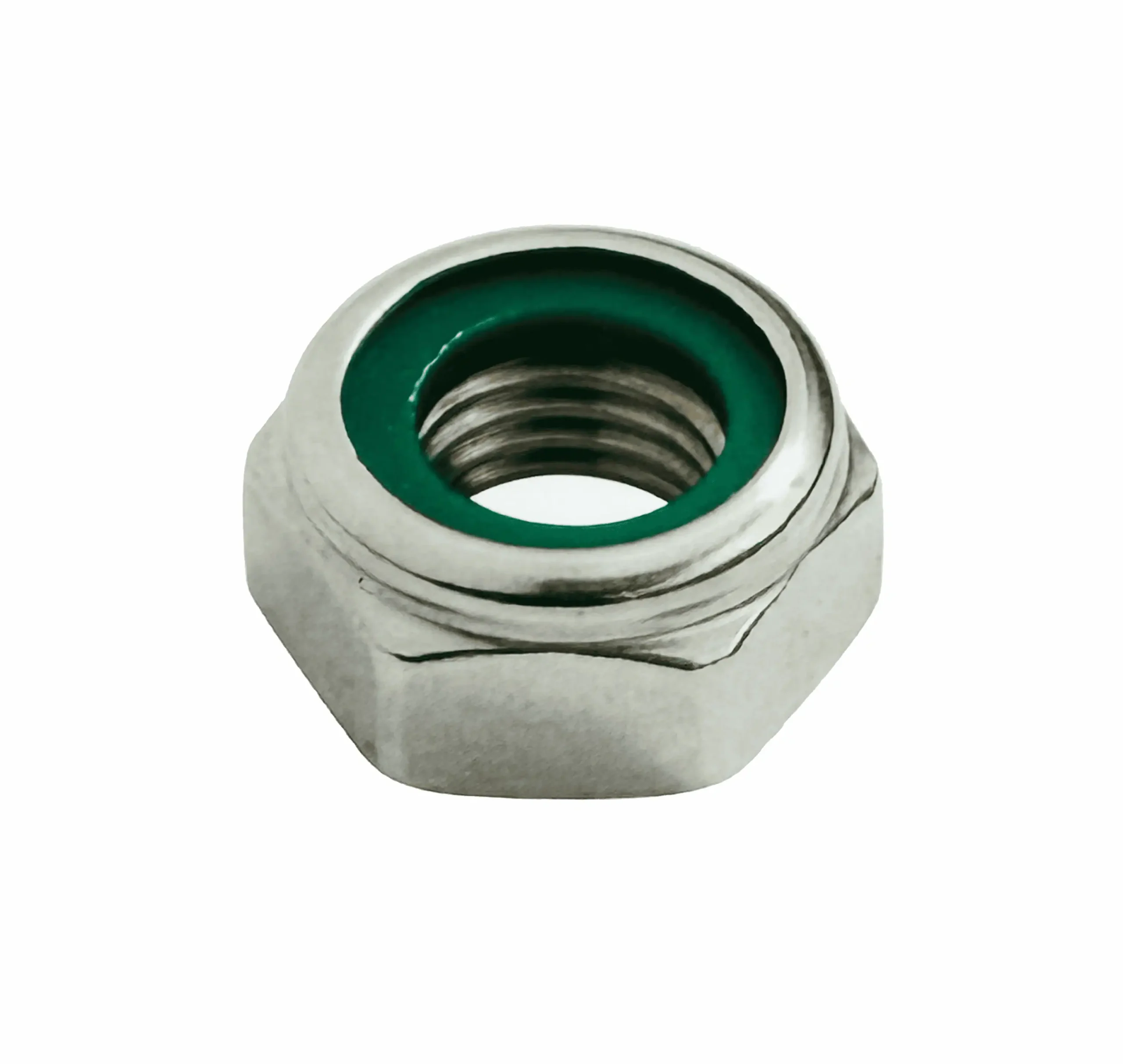
Nylon Material: Virgin PA66 (Standard colors: Blue/Green/White; custom colors available).
Readiness: EN 10204 3.1 Certification, PPAP Level 3, and 100% Optical Sorting for insert presence.
Types of Nylon Insert Lock Nut
 Special Nuts
Weld Nuts Series
Inserts & Rivet Series
Furniture & Specialty
Nylon Insert Lock Nut
The Engineering Advantage: Prevailing Torque Explained
Why specify a Nyloc nut over a standard hex nut and lock washer? It comes down to constant tension versus friction. A standard nut relies solely on clamp load friction to stay tight. Once vibration momentarily overcomes that friction, the nut spins free.
A Nylon Insert Lock Nut creates Prevailing Torque. When the bolt threads enter the undersized nylon ring, the nylon doesn’t cut; it cold-flows and compresses elastically around the threads. This creates a permanent, 360-degree radial compressive force. Even if the bolt loses all axial clamp load due to vibration or thermal expansion, the nylon’s elastic memory holds the nut firmly in place on the thread.

What Is A Nylon Insert Lock Nut?
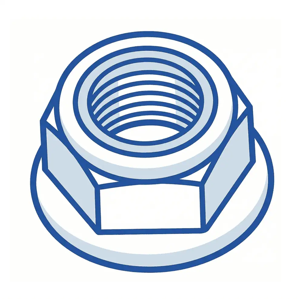
Nylon insert lock nuts are hex nuts with a captive polymer ring at the top that creates prevailing torque on the mating bolt thread. The nylon insert resists loosening under vibration by elastic interference, making these nuts common in automotive, appliances, machinery, and equipment assemblies.
- Hex body provides reliable wrench engagement and torque transfer in manual and automated assembly tools.
- Top nylon insert creates controlled thread interference for vibration-resistant locking without liquid threadlocker.
- Chamfered thread entry improves bolt lead-in and reduces cross-thread starts during powered run-down.
- Swaged top collar mechanically retains the nylon insert during transport and vibratory feeding.
- Standardized outer geometry supports common sockets, feeders, and assembly fixtures across OEM lines.
| Fastener Type | Locking Method | Vibration Resistance | Service Temperature Suitability | Typical Use Case |
|---|---|---|---|---|
| Nylon Insert Lock Nut | Nylon insert prevailing torque | High (within validated temp range) | Limited by nylon material | Automotive, appliances, general machinery |
| All-Metal Lock Nut | Metal thread deformation | High | Better for higher temperatures | Engine-adjacent / high-temp applications |
| Standard Hex Nut + Washer | No self-locking feature | Low (depends on joint design) | Broad | Static, low-vibration joints |
| Threadlocker + Standard Nut | Adhesive locking | Medium to High (process-dependent) | Depends on adhesive grade | Service assemblies with controlled curing |
| Clinch Nut (Sheet-Metal Insert) | Mechanical clinch in sheet | Not a bolt locking nut by itself | Depends on base material/system | Thin sheet threaded attachment points |
Dimensional Reference (Standard Table)
Typical Industry Reference Dimensions (DIN 985 / ISO 10511 style, low type)
Note: Exact dimensions vary by standard revision, property class, and customer drawing. Final production dimensions are subject to customer drawing and assembly process validation.
| Thread Size | Pitch (mm) | Across Flats s (mm) | Overall Height m (mm, ref.) | Thread Class (Typical) | Insert Position |
|---|---|---|---|---|---|
| M3 | 0.5 | 5.5 | 4.0 | 6H | Top captive nylon insert |
| M4 | 0.7 | 7.0 | 5.0 | 6H | Top captive nylon insert |
| M5 | 0.8 | 8.0 | 5.0 | 6H | Top captive nylon insert |
| M6 | 1.0 | 10.0 | 6.0 | 6H | Top captive nylon insert |
| M8 | 1.25 | 13.0 | 8.0 | 6H | Top captive nylon insert |
| M10 | 1.5 | 17.0 | 10.0 | 6H | Top captive nylon insert |
| M12 | 1.75 | 19.0 | 12.0 | 6H | Top captive nylon insert |
| M16 | 2.0 | 24.0 | 16.0 | 6H | Top captive nylon insert |
Customization Notes
Dimensions can be customized for OEM socket access, wrench envelope, mating bolt class, and automated feeding requirements.
Critical dimensions (e.g., across flats, nut height, thread lead-in) can typically be controlled to ±0.05 mm on selected features, subject to part size, geometry, tooling condition, and production volume.
Prevailing torque windows should be defined together with the mating bolt specification, surface finish, and lubrication condition.
Factory Engineering: Solving OEM Assembly Failures
1) Torque Scatter Causes Driver Shutdowns or Under-Clamp
Pain Point:
On automated assembly lines, some nuts run too tight and stall the driver, while others run too loose and risk insufficient clamp load.Root Cause (Engineering):
Variation in thread geometry, nylon insert interference, insert moisture condition, and coating thickness stack-up causes a wide prevailing torque distribution.Our Factory Solution:
Thread process control with GO/NO-GO gauge discipline and thread profile checks
Top collar swage height control (SPC on retention geometry)
Nylon insert incoming lot control (material spec + moisture conditioning window)
Lot-based prevailing torque validation per agreed ISO 2320 test method
Verification Method:
Prevailing-on torque and removal torque records, dimensional SPC, torque trend by lot, retained samples for traceability.
2) Nylon Insert Falls Out or Rotates During Feeding / Transport
Pain Point:
Insert displacement is found after bulk transport, vibratory bowl feeding, or repeated handling, causing field complaints and line rejects.Root Cause (Engineering):
Inconsistent swaged top collar geometry, insufficient retention lip formation, or local cracking/deformation at the insert pocket due to tooling wear.Our Factory Solution:
Swaging tooling wear monitoring and replacement interval control
Insert pocket geometry inspection (top collar formation height / retention profile)
Camera inspection for insert presence and top-collar shape (100% visual sorting if required)
Retention validation tests under agreed handling simulation conditions
Verification Method:
Insert presence optical inspection records, retention pull/press test data (customer-defined), lot traceability and CAPA logging.
3) Cross-Threading and False Starts on High-Speed Assembly
Pain Point:
Nutrunners show sudden torque spikes at the first turns; operators report “tight nuts,” but root cause is cross-thread starts and poor lead-in.Root Cause (Engineering):
Thread entry burrs, damaged first thread after coating, insufficient chamfer consistency, or thread-to-hex coaxiality drift.Our Factory Solution:
Controlled thread lead-in chamfer formation and deburring
Thread quality inspection using GO/NO-GO and periodic profile verification
Optical sorting for thread mouth damage and obvious plating clogging
Coaxiality/perpendicularity control on critical OEM programs
Verification Method:
Run-down trials with customer bolts, thread gauge records, sorting escape rate tracking, assembly line correlation trials.
Industry Application Case Study (STAR Format)
Client Background
A European appliance manufacturer assembling vibration-prone motor bracket modules, consuming approximately 1.2 million M6 lock nuts per month across two automated lines.
Situation
The customer used standard M6 nylon insert lock nuts from multiple suppliers. The line had intermittent driver over-torque alarms and inconsistent cycle time during final tightening.
Task
Stabilize assembly torque behavior while maintaining vibration resistance and no change to the customer’s existing socket tools, mating bolts, or bracket design.
Challenge
Investigation showed the issue was not only driver settings. The customer had:
wide prevailing torque variation between lots
occasional damaged first thread at the nut entry
insert retention inconsistency after vibratory feeding
This caused false starts, torque spikes, and line stoppages.
Our Solution
We implemented a controlled OEM program with:
tighter control on thread lead-in chamfer and first-thread integrity
SPC on top collar swage geometry for insert retention consistency
lot-based prevailing torque validation using the customer’s actual mating bolt and lubrication condition
optional 100% optical sorting for insert presence and thread mouth defects on critical lots
Result
Within 8 weeks of phased validation and production release:
driver over-torque shutdown events reduced by 78%
nut-related line stoppage time reduced by 61%
incoming fastener rejection improved from 3,400 ppm to 280 ppm
assembly cycle time variation narrowed, improving line balance stability without changing tool hardware
FAQ
Are nylon insert lock nuts reusable?
Yes, but with diminished performance. The nylon ring’s elastic memory degrades after the first use. While ISO standards allow for multiple uses (often up to 5 times depending on the spec), the prevailing torque drops significantly after the first removal. For critical safety applications, we always recommend using a new nut every time.
What is the temperature limit for these nuts?
The limiting factor is the nylon insert, not the steel body. Standard PA66 nylon is rated for continuous operating temperatures from -40°C to +120°C (-40°F to +248°F). If your application exceeds this range (e.g., exhaust manifolds or cryogenic equipment), you must switch to an All-Metal Lock Nut.
Why is there a gap between the bolt end and the nylon ring?
For the locking mechanism to work, the bolt threads must fully engage and pass through the nylon ring. A general rule of thumb is that at least two full bolt threads should protrude past the top of the nut to ensure the nylon has been fully compressed and is generating maximum prevailing torque.
How should we set tightening torque for nylon insert lock nuts on an automated line?
Do not use prevailing torque as the final tightening torque target. First, define the required clamp load for the joint (based on bolt grade, joint material, and safety factor), then establish installation torque under your actual lubrication/coating condition. Measure prevailing torque separately (before seating) and include it in process validation. Use your production bolt, not a lab substitute, because friction and coating thickness strongly affect the torque curve.
Can nylon insert lock nuts be used after high-temperature coating or paint-bake processes?
Use caution. Nylon insert lock nuts are generally not suitable for post-assembly thermal exposure beyond the nylon material’s validated temperature range. Paint-bake cycles, curing ovens, or nearby heat sources can reduce locking performance by relaxing the insert. If thermal exposure is unavoidable, validate prevailing torque retention after the full thermal cycle, or switch to an all-metal prevailing torque lock nut.
What process settings reduce cross-threading and torque spikes in automated assembly?
Control alignment before increasing speed. Verify socket concentricity, bolt presentation angle, and seating stability of the joint stack-up. Use a short low-speed engagement stage until 2–3 threads are formed, then ramp to production speed. Monitor torque-angle traces for early spikes, which often indicate thread entry damage, chamfer inconsistency, or plating build-up—not necessarily driver malfunction.