Specialty Fastening Solutions · OEM Flange Weld Nut Manufacturer
Flange Weld Nuts: Precision Load Distribution for Thin Sheet Metal & High-Torque Assemblies
Standard fasteners often fail when extreme clamp loads meet thin-gauge sheet metal. As a 30-year direct manufacturer of special nuts, we engineer Hex Flange Weld Nuts (ISO 21670 & Custom OEM) to solve catastrophic pull-through failures. By integrating a precision hex body with an oversized, load-distributing circular flange, we provide the ultimate structural anchor for thin panels. We control our 3-point weld projections to a strict ±0.05mm tolerance, guaranteeing equal electrical fusion and absolute joint integrity for your automated lines.
Standard Compliance: ISO 21670, DIN EN equivalents, and Non-Standard OEM Prints.
Specialty Customization: Oversized flange diameters, modified pilot heights, and heavy-gauge projections.
Materials: C1010/C1015 Low Carbon Steel (Weld-Optimized), 304/316 Stainless Steel.
Readiness: EN 10204 3.1 Certification, PPAP Level 3, and 100% Optical Laser Sorting.
Types of Flange Weld Nuts
 Special Nuts
Weld Nuts Series
Inserts & Rivet Series
Furniture & Specialty
Piloted Hex Flange Weld Nut (Self-Locating)
Standard Hex Flange Weld Nut (Flat Flange Base)
Custom Oversized Flange Nuts (Specialty OEM)
The Engineering Advantage: The "Snowshoe" Effect
Why classify this as a “Special Nut” rather than a standard fastener? It comes down to Surface Area Physics. When high torque is applied to a bolt mated with a standard hex nut on sheet metal thinner than 1.5mm, the concentrated stress can cause the nut to pull straight through the panel (tear-out). The oversized circular flange of our weld nuts acts like a snowshoe—it massively increases the bearing footprint, distributing the kinetic clamp load safely over a wider radius. This permanently prevents panel warping, distortion, and joint failure under heavy mechanical vibration.
What Is A Flange Weld Nut?
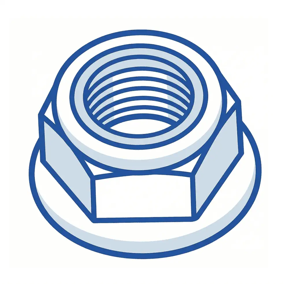
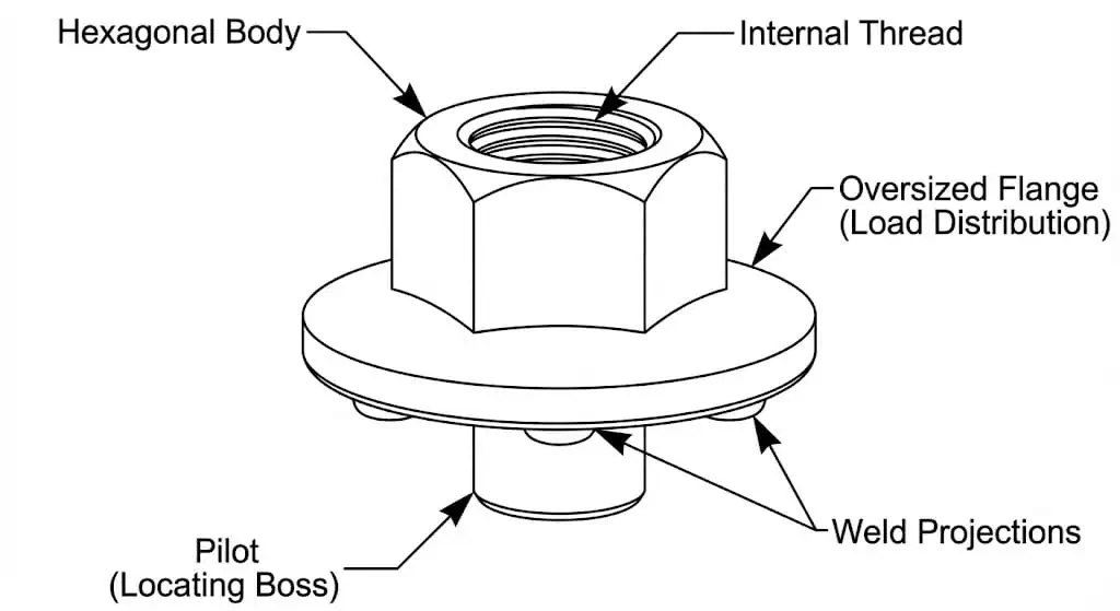
A flange weld nut is a specialized cold-formed industrial fastener that combines a standard hexagonal wrenching body with an integrated, oversized circular base (flange). Designed specifically for resistance projection welding onto thin-gauge sheet metal, the wide flange acts as a built-in structural washer. It distributes high clamping loads over a larger surface area, preventing the nut from pulling through or distorting the host panel under torque.
Key Anatomy & Characteristics:
Oversized Flange (Bearing Surface): A wide, flat circular base extending significantly beyond the hex body. Its primary function is to maximize ground contact, reducing surface pressure on thin metals to prevent tear-out failures.
Weld Projections: engineered dimples (typically three or more) located on the underside of the flange. They concentrate the welding current to ensure simultaneous, uniform fusion across the wide base.
Pilot (Locating Boss): A central protruding ring that self-centers the nut in pre-punched holes for automated assembly and shields internal threads from weld spatter.
Hexagonal Body: Provides a standard wrenching surface for applying final torque to the mating bolt.
Dimensional Reference: ISO 21670 Hexagon Flange Weld Nuts
(Note: As an OEM manufacturer, we specialize in modifying flange diameters and projection geometries to match your exact assembly requirements.)
| Thread Size | Pitch (mm) | Hex Width Across Flats (Max) | Flange Diameter (Max) | Nut Height (Max) | Recommended Sheet Thickness |
| M5 | 0.80 | 8.00 mm | 11.00 mm | 5.50 mm | 0.8 – 1.2 mm |
| M6 | 1.00 | 10.00 mm | 13.00 mm | 6.50 mm | 1.0 – 1.5 mm |
| M8 | 1.25 | 13.00 mm | 17.00 mm | 8.00 mm | 1.2 – 2.0 mm |
| M10 | 1.50 | 15.00 mm | 19.00 mm | 9.50 mm | 1.5 – 2.5 mm |
| M12 | 1.75 | 18.00 mm | 24.00 mm | 12.00 mm | 2.0 – 3.5 mm |
Factory Engineering: Solving OEM Assembly Failures
Pain Point 1: One-Sided “Cold Welds” on the Flange Edge
The Cause: The larger diameter of the flange pushes the weld projections further outward. If the projections are uneven, or if the upper welding electrode does not cover the entire flange evenly, the electrical current bypasses the shorter dimples, leading to a weak, one-sided weld.
Our Solution: We employ 360-degree inline optical laser sorting. Every single flange nut is scanned to ensure the 3 projections are perfectly level within a ±0.05mm tolerance. This guarantees that standard flat-faced copper electrodes achieve uniform current flow across all points.
Pain Point 2: Thread Embrittlement Under Vibration
The Cause: Sourcing flange nuts made from cheap, high-carbon scrap steel. The rapid heating and cooling cycle of resistance welding turns high-carbon steel into brittle martensite, causing the nut to shear off under dynamic loads.
Our Solution: We strictly cap the Carbon Equivalent (CE) of our raw wire rods to < 0.20%. Using pure C1010/C1015 steel ensures a ductile, shock-absorbing weld joint that bends before it breaks.
Industry Application Case Study
Sector: Commercial Electric Vehicle (EV) Battery Trays
The Challenge: A Tier-1 automotive supplier was using standard hex weld nuts on 1.2mm lightweight steel EV battery trays. During 10G frequency vibration testing, the concentrated weight of the battery modules caused the standard nuts to punch cleanly through the thin steel trays, resulting in catastrophic battery detachment.
Our Solution: Our engineering team transitioned the client to an M8 Flange Weld Nut, but we custom-headed the flange diameter to 19.0mm (2mm wider than the ISO standard) to maximize the load distribution. We strictly utilized C1010 bare steel to ensure rapid, crack-free fusion without burning through the 1.2mm tray.
The Result: The oversized flange dispersed the kinetic load safely across the thin steel. The battery trays passed the 10G vibration test with 0 PPM pull-through failures, saving the client from an expensive, heavy redesign of the entire tray architecture.
FAQ
Do flange weld nuts require different welder settings than standard hex nuts?
Yes. Because the flange creates a larger overall footprint and the weld projections are spaced further apart, you generally need to increase your Electrode Force (Squeeze Pressure) by 10-15%. This ensures the larger nut seats completely flat against the panel before the welding current fires. Failure to apply enough pressure will result in molten metal expulsion (spatter) shooting out from under the flange.
Can we zinc-plate the flange nuts before welding to prevent rust in storage?
Zinc vaporizes at 907°C, which is roughly 500°C below the melting point of the steel projections. When the welder fires, the trapped zinc underneath the wide flange vaporizes violently, blowing the molten steel apart, creating severe porosity (voids), and releasing toxic fumes. Order them plain/bare or lightly oiled, weld them to your chassis, and then electroplate or E-coat the entire completed assembly.
How do we inspect the weld quality hidden underneath the large flange?
Unlike standard hex nuts where the weld fillet might be slightly visible from the side, a proper flange weld is completely hidden beneath the wide bearing surface. You must rely on destructive testing (Push-Out or Torque-to-Yield testing) on sample batches during your machine setup phase. We provide destructive test data reports alongside our PPAP Level 3 documentation to baseline your welder settings.