Industrial Fastening Solutions · OEM All-Metal Lock Nuts Manufacturer
All-Metal Lock Nuts for High-Temperature and Vibration-Critical Bolted Joints
In vibration-prone assemblies, lock performance is not solved by torque increase alone. The locking zone geometry, thread quality, mating bolt coating, and seating behavior must be validated as one system. This Special Nuts category covers three common all-metal locking designs—hex flange, oval lock (Stover type), and top lock style—for different temperature, vibration, and installation constraints. Send your drawing, mating bolt specification, coating/lubrication condition, and EAU for quotation and production validation planning.
Product Scope: Hex flange all-metal lock nuts, oval lock (Stover type), top lock style
Manufacturing Basis: Standard-style equivalents + OEM drawing-based production
Typical Size Range: Metric M5–M30 (depends on design and application)
Materials: Carbon steel, alloy steel, stainless steel
Surface Finishes: Plain, zinc plated, zinc-nickel, phosphate/oil, black finish (subject to property class and process validation)
Validation / Reports: GO/NO-GO thread gauges, dimensional inspection, hardness test, prevailing torque test (ISO 2320 method), EN 10204 3.1 on request
Types of All-Metal Lock Nuts
 Special Nuts
Weld Nuts Series
Inserts & Rivet Series
Furniture & Specialty
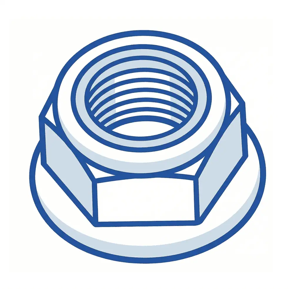
All-Metal Hex Flange Lock Nut
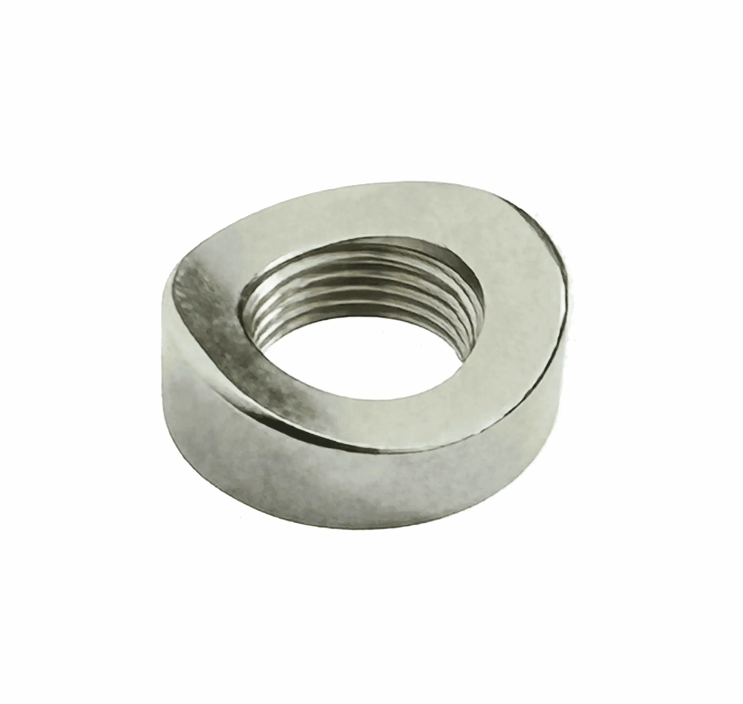
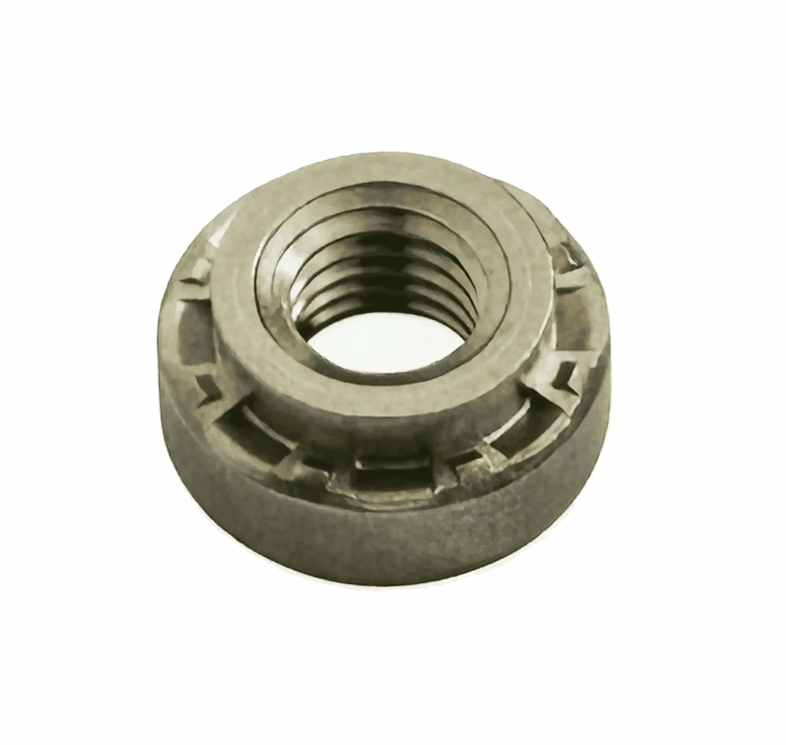
All-Metal Prevailing Torque Lock Nut (Oval Lock Stover Type)
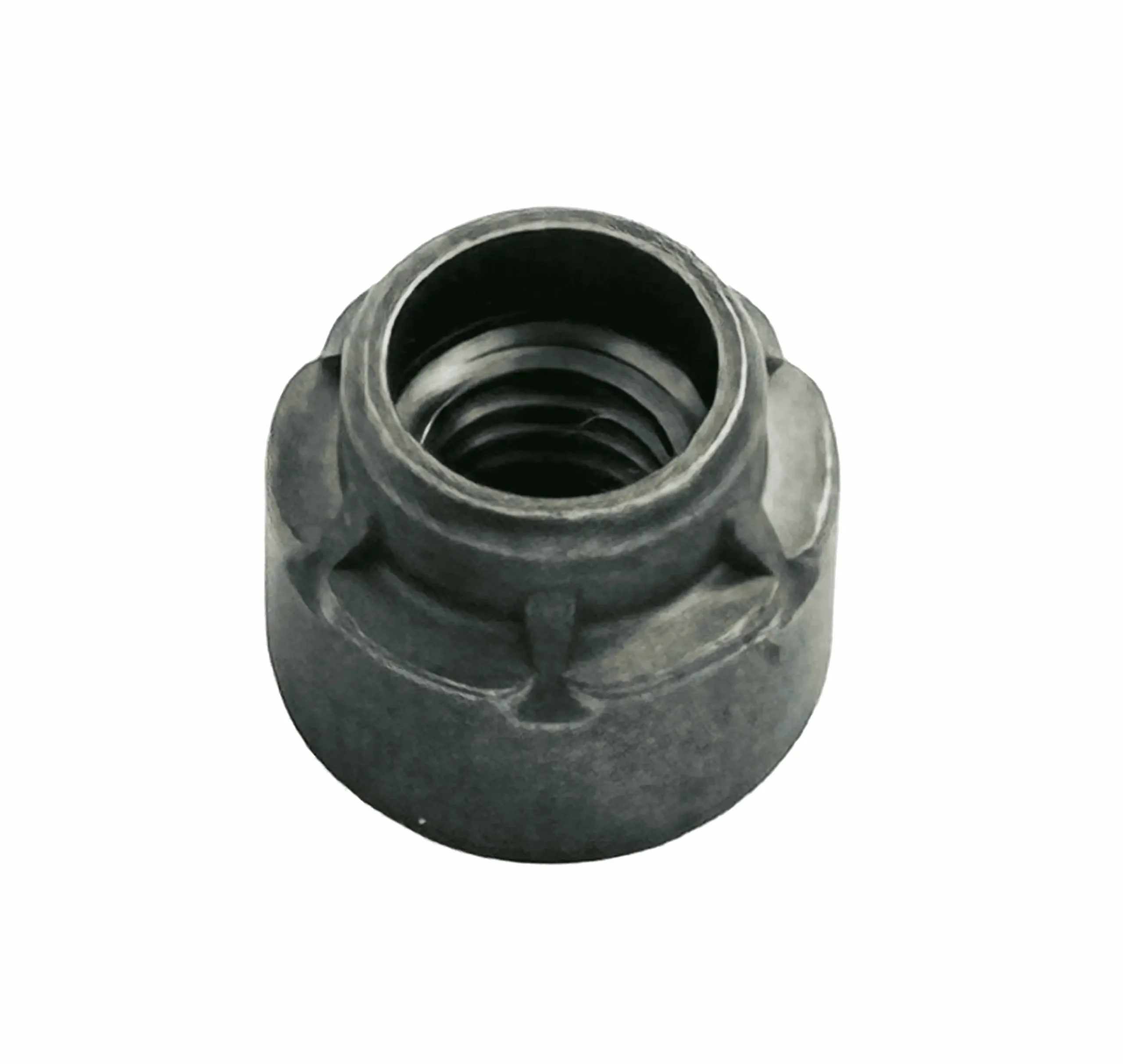
All-Metal Prevailing Torque Lock Nut (Top Lock Style)
Why All-Metal Lock Nut Designs Are Not Interchangeable
Many RFQs use “all-metal lock nut” as one generic category. In production assembly, that assumption often causes torque instability, seating problems, or revalidation delays. The locking principle may be similar (metal thread interference), but locking-zone geometry and seating design change how the nut behaves on the line.
A flange lock nut changes contact behavior at the joint surface. Stover-type and top lock styles change prevailing torque behavior through different deformed thread zones. If the bolt coating, lubrication, or tool strategy changes, the torque-angle response can also change.
What should be checked before release:
Seating support needed (flange vs non-flange)
Locking geometry type (oval lock vs top lock)
Mating bolt thread/coating compatibility
Prevailing torque + torque-angle validation on the actual joint system

What Is All-Metal Lock Nut?
All metal lock nuts are self-locking nuts that create prevailing torque through controlled metal thread deformation instead of a nylon insert. They are commonly used in high-temperature or vibration-critical assemblies where polymer insert lock nuts may lose locking performance.
- Distorted thread zones create prevailing torque without polymer inserts or liquid threadlocker.
- Flange designs add bearing area and can improve seating on brackets or stamped parts.
- Oval lock and top lock styles support elevated-temperature applications where nylon inserts are unsuitable.
- Assembly torque behavior depends on locking geometry, bolt coating, and thread condition.
- OEM release should validate the full nut-bolt-joint system, not the nut alone.
| Fastener Type | Locking Method | Temperature Suitability | Seating Behavior | Typical Use Case |
|---|---|---|---|---|
| All-Metal Hex Flange Lock Nut | Distorted metal thread | High (application-dependent) | Wider bearing surface | Brackets, frames, chassis joints |
| All-Metal Prevailing Torque Nut (Oval Lock / Stover Type) | Ovalized top locking zone | High | Non-flange seating | Heavy equipment, engine-adjacent supports |
| All-Metal Prevailing Torque Nut (Top Lock Style) | Top distorted thread zone | High | Non-flange, compact layout | Machinery, transport, compact assemblies |
| Nylon Insert Lock Nut | Nylon insert prevailing torque | Limited by polymer temperature range | Standard nut seating | General vibration-resistant assemblies |
Dimensional / Technical Reference (Category Comparison Table)
Typical Category-Level Technical Reference (for Selection Discussion Only)
Exact dimensions depend on standard family, material grade, locking geometry design, and customer drawing. Final values are subject to customer drawing and process validation.
| Market Description | Locking Type | Typical Thread Range* | Flange Presence | Seating Character | Temperature Suitability (Qualitative) | Typical Applications | Validation Note |
|---|---|---|---|---|---|---|---|
| All-Metal Hex Flange Lock Nut | Distorted thread + flange seating | M6–M16 (typical) | Yes | Wider bearing surface | High (application-dependent) | Brackets, chassis, appliance frames | Validate seating + prevailing torque with actual joint |
| All-Metal Prevailing Torque Lock Nut (Oval Lock / Stover Type) | Ovalized top locking zone | M5–M24 (typical) | No | Compact non-flange locking style | High (application-dependent) | Heavy equipment, compressors, engine-adjacent supports | Validate torque window with actual bolt/coating |
| All-Metal Prevailing Torque Lock Nut (Top Lock Style) | Top distorted thread zone | M5–M24 (typical) | No | Compact locking style with separate seating strategy | High (application-dependent) | Industrial machinery, transport assemblies, compact joints | Validate torque-angle behavior and seating stack-up |
*Thread ranges are typical category references and may vary by drawing, material, and production program.
Customization & Tolerance Notes
Dimensions, locking-zone geometry, and seating features can be customized for OEM applications.
Critical features (across flats, nut height, locking deformation profile, flange face geometry) can be controlled under SPC on qualified high-volume programs.
Final torque requirements must be defined with the actual mating bolt thread class, coating thickness, lubrication condition, and installation process.
Factory Engineering: Solving OEM Assembly Failures
Failure 1: Prevailing Torque Drifts Between Lots
Pain Point:
Incoming inspection alternates between “too tight” and “too loose” lots, although the customer ordered the same product family.Root Cause (Engineering):
Variation in distorted-thread geometry, thread surface condition, hardness window, or coating friction shifts prevailing torque beyond the specified band.Our Factory Solution:
SPC on locking-zone forming parameters (deformation profile by design type)
GO/NO-GO thread gauge control + periodic thread profile verification
Hardness verification by lot where required
ISO 2320 prevailing torque validation using agreed bolt specification
Verification Method:
Prevailing-on / removal torque records, SPC trend charts, hardness reports, retained lot samples with traceability.
Failure 2: Tool Trips and Torque Spikes on Automated Rundown
Pain Point:
Assembly tools fault intermittently during early thread engagement, especially at high production speed.Root Cause (Engineering):
The issue is often a combined effect of thread entry quality, locking-zone interference distribution, and mismatch with the actual production bolt coating/lubrication condition.Our Factory Solution:
Thread entry burr and defect inspection
Model-specific locking-zone consistency checks (oval lock vs top lock geometry)
Validation using the customer’s production bolt and coating condition
Pilot-line torque-angle correlation support before mass release
Verification Method:
Torque-angle trace comparison, thread inspection records, pilot assembly trial data, lot-based torque validation.
Failure 3: Clamp Load Scatter on Flange-Supported Joints
Pain Point:
Tightening torque appears stable, but clamp retention varies and field feedback shows inconsistent joint settling.Root Cause (Engineering):
Seating interface variation (flange face geometry, bracket flatness, friction condition, embedment) is affecting clamp behavior. If prevailing torque is not separated from seating torque during validation, the diagnosis is often incorrect.Our Factory Solution:
Flange face dimensional control and seating surface inspection
Joint-specific validation using actual bracket material and finish
Separate prevailing torque from seating torque during process development
Review washer strategy and contact surface requirements
Verification Method:
Dimensional reports, torque-angle traces, line trials, clamp-load correlation testing (if required by project).
Industry Application Case Study (STAR Format)
Client Background
A European industrial equipment manufacturer producing vibration-loaded motor support assemblies with annual demand above 1.8 million lock nuts.
Situation
The customer sourced multiple all-metal lock nut designs and treated them as interchangeable because the product descriptions were similar.
Task
Stabilize assembly performance and reduce incoming variation without changing socket tooling or redesigning the joint.
Challenge
Production data showed three different failure patterns:
torque spikes during rundown in one assembly line
unstable prevailing torque on incoming lots
clamp retention variation on flange-supported joints
The root cause was not “lock nut quality” in a generic sense, but mismatched locking and seating geometries across different applications.
Our Solution
We reclassified the customer’s applications by joint behavior:
flange-supported joints used flange lock nuts
heat/vibration locations used oval lock prevailing torque nuts
compact assemblies used top lock style nuts
Each design was validated with the customer’s actual bolts, coatings, and tool settings, with lot-based torque records provided for release control.
Result
Within the first production release cycle:
nut-related assembly faults decreased by 68%
incoming fastener rejection dropped from 2,400 ppm to 320 ppm
tool fault events linked to torque spikes were reduced by over 70%
no tooling hardware replacement was required
FAQ
How do we choose between a Stover-type nut and a top lock style nut?
Start with the joint condition, not the name. Both are all-metal prevailing torque nuts, but they use different locking-zone geometries and can produce different torque-angle behavior. If your assembly is tool-sensitive, validate both styles using the actual bolt coating, lubrication condition, and rundown strategy before release.
Can all-metal lock nuts be reused?
They may be reusable in some maintenance situations, but reuse must be validated by the application owner. Prevailing torque can change after repeated installation cycles, especially when the mating bolt thread is worn, coated, or damaged. For critical joints, define reuse limits using measured torque retention data.
Why is installation torque unstable even when the lock nut type is correct?
The nut type may be correct, but the nut-bolt system may not be validated. Installation torque instability is commonly caused by thread entry defects, locking-zone variation, bolt coating friction, or seating surface issues. Review torque-angle traces, thread inspection data, and prevailing torque results together rather than adjusting tool settings only.