
Pipe fittings vs flanges come down to one practical question: do you need a permanent joint, or a joint you can safely open and re-make on demand? Pipe fittings (welded, socket-welded, threaded, or specialty) are the workhorse for permanent geometry changes—direction, branch, reduction—especially where vibration, thermal cycling, and limited access make rework expensive. Flanges are the right choice when your system needs planned access (pump removal, strainer cleaning, inspection ports), modular upgrades, or code-driven periodic maintenance.
Pressure rating, temperature, fluid compatibility, and assembly procedure drive the decision. Standards define what “rated” really means: ASME B16.9 covers factory-made wrought butt-welding fittings, ASME B16.11 covers forged socket-weld and threaded fittings, and ASME B16.5 covers pipe flanges and flanged fittings (sizes and ratings by class/material group). For operational isolation hardware installed between flanges, ASME B16.48 covers line blanks. (Market size is business context—not a design basis. If you need the market reference, the flange market figure cited here comes from Grand View Research.)
Pipe Fittings Overview
Definition & Function
Pipe fittings are the components used to connect, adapt, and route flow in a piping system—straight runs, direction changes, diameter transitions, and branch connections. In the field, fittings also decide how inspectable and repairable a line will be. A butt-weld elbow in a rack is “set-and-forget” if welding and inspection are controlled; a threaded adapter in a vibrating skid is a known leak candidate unless the joint type and sealing method match the service.
Tip: Treat the joint type as part of the hazard analysis. The same nominal “fitting” behaves very differently depending on whether it’s butt-weld, socket-weld, threaded, or compression—especially under vibration, thermal cycling, or corrosive media.
- Create permanent geometry changes (elbows, tees, reducers, caps) with standardized dimensions and tolerances
- Adapt between connection systems (welded-to-threaded, metric-to-inch, instrument takeoffs)
- Control and isolate flow when integrated with valves, strainers, and instrument manifolds
Common Types
You will find several fitting families, each with a “best fit” use case. When you specify fittings, call out both the geometry and the end connection. That’s where most field problems start.
- Elbows: Change the direction of flow (long radius vs short radius affects layout and pressure drop)
- Tees: Create branch connections (branch reinforcement must match code and thickness)
- Couplings: Join two pipes together (often used in threaded utility services)
- Reducers: Connect pipes of different diameters (check eccentric vs concentric for drainability and pump suction)
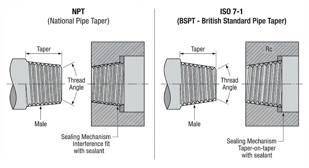
- Adapters: Transition between different connection types (thread standards matter—NPT vs BSPT/ISO 7-1 are not interchangeable)
- Caps: Seal the end of a pipe (consider future access: cap vs blind flange vs line blank)
- Branch Pipe Seats: Add branches without losing pressure (verify reinforcement and weld details)
- Pipe Clamps: Support and secure pipes (support design controls vibration and fatigue at joints)
Note: “High pressure” is not a label—it’s a design condition. In practice, butt-weld and properly executed socket-weld systems are used for severe services more often than threaded joints because the sealing mechanism is not dependent on thread interference or sealant.
Best Use Cases
Pipe fittings work best where you want a permanent, compact layout and you do not plan to break the joint during routine maintenance. Typical examples include high-temperature utility lines, process headers, and dense pipe racks where bolt access is limited.
- Process piping in chemical and petrochemical plants (code-driven fabrication/inspection)
- Hydraulic and pneumatic skids where routing is tight and vibration management is critical
- Heat transfer, evaporation, and distillation systems where insulation and thermal growth drive compact welded layouts
- Instrument takeoffs and analyzer panels where leak class and maintainability must be balanced
You should choose pipe fittings when your system needs compact routing, fewer “break points,” and controlled fabrication quality. If the system will be opened frequently (strain cleaning, CIP/SIP breaks, pump pull-outs), plan flanged or hygienic clamp interfaces at the maintenance boundary instead of forcing repeated cut-and-reweld repairs.
Field example (leak troubleshooting): A vibrating hydraulic power unit showed recurring seepage at a threaded reducer near the pump discharge. The root cause was a mismatch between thread form/seal method and vibration: sealant cured unevenly, then micro-movement opened a helical leak path. Corrective action was to relocate the transition away from the vibration source and convert the joint to a welded spool with a service flange at the pump boundary, so maintenance stayed “bolts-and-gasket,” not “threads-and-hope.”
Materials & Standards (Brief)
Selecting the right material and standard is what makes the fitting “inspectable” and “auditable,” not just “installed.” The standards below define dimensions, tolerances, marking, and (where applicable) rating rules for common fitting categories.
| Standard | Description |
|---|---|
| ASME B16.9 | Overall dimensions, tolerances, ratings, testing, and markings for factory-made wrought butt-welding fittings |
| ASME B16.11 | Ratings, dimensions, tolerances, marking, and material requirements for forged socket-weld and threaded fittings |
| ASTM A105/A105M | Carbon steel forgings for piping applications (commonly used for forged components in carbon steel piping systems) |
| ASTM A403/A403M | Wrought austenitic stainless steel fittings (common basis for 304/316 stainless fitting material specifications) |
| ISO 7-1 (thread concept) | Pipe threads intended for pressure-tight joints made on the threads (do not mix with NPT/BSPP without a verified sealing design) |
When comparing Pipe Fittings vs Flanges, fittings are usually the first choice for permanent routing and compact systems—provided fabrication quality, inspection access, and code requirements are planned up front.
Flanges Overview
Definition & Function
You use flanges to create a bolted interface between pipes, valves, pumps, heat exchangers, and other equipment. The engineering value is not “strength”—it’s repeatable access. A flanged joint gives you a defined gasket seat, bolting pattern, and standardized dimensions so you can open the system, service equipment, and restore sealing without cutting.
Key functions of flanges in modular piping systems:
- Provide standardized interfaces (dimensions, facing, bolt patterns by class and size)
- Enable equipment removal (pumps, strainers, control valves) without cutting the pipe
- Support isolation hardware (spades/spectacle blinds/line blanks) where operations require positive isolation
- Accommodate inspection and cleaning boundaries in hygienic services (when specified)
- Restore service faster after maintenance—if gasket selection and bolt-up are controlled
Types of Flanges
You will find several flange types, each designed for a particular stress/installation profile. Don’t pick by “popular type”—pick by load path, inspection access, and expected maintenance frequency.
- Weld Neck Flange: Best for high-stress services; the tapered hub helps reduce bending stress at the weld.
- Slip-On Flange: Easier fit-up; commonly used where stress is lower and access is good (verify weld details and inspection requirements).
- Blind Flange: Closes the end of a pipe or nozzle; used for isolation, pressure test boundaries, and future tie-ins.
- Socket Weld Flange: Used in small-bore, higher-pressure piping; pay attention to crevice/corrosion risk and code restrictions for certain services.
- Lap Joint Flange: Rotates for alignment; commonly used with a stub end when frequent disassembly or alignment flexibility is required.
Tip: If you expect repeated maintenance, specify the joint as a “system”: flange standard + facing + gasket standard + bolt/nut grades + tightening procedure. That’s how you control leak risk, not by flange type alone.
Ideal Applications
You should choose flanges when your system requires routine access, planned upgrades, or validated cleaning/inspection boundaries. They are common at equipment nozzles, removable spools, and isolation points.
| Application Type | Description |
|---|---|
| Fluid Transfer | ASME B16.5 flanges connect piping to valves, pumps, and equipment with standardized dimensions and ratings. |
| Chemical Mixing | Removable spools and equipment connections allow inspection, cleaning, and seal replacement without cutting the line. |
| Water-for-Injection (WFI) Systems | Where hygienic design is specified, interfaces are often selected to support cleanability, inspection, and documentation (e.g., ASME BPE guidance). |
- Stainless steel flanges (e.g., common 304/316 grades) are selected where corrosion resistance and cleanability are required—final material selection must match chloride level, temperature, and cleaning chemistry.
- Facing type and gasket selection control leak performance far more than “brand.” Use a gasket standard (e.g., metallic gaskets per ASME B16.20) where applicable and match the facing to the gasket design.
- For positive operational isolation between flanges, use an operational line blank standard (ASME B16.48) rather than improvised plates.
Materials & Standards (Brief)
You need to select flange materials and ratings based on temperature, pressure, corrosion mechanism, and code limits. Pressure–temperature rating is not a single number; it changes with temperature and depends on the material group in the standard.
| Flange Material Name | Chemical Composition/Characteristics | Applicable Environment | Application Area |
|---|---|---|---|
| ASTM A182 F5 | Cr-Mo alloy steel; chosen for elevated-temperature strength and oxidation resistance relative to plain carbon steel | Elevated-temperature services (confirm allowable stress and flange class by temperature) | Oil, chemical, power |
| ASTM A182 F9 | Higher chromium alloy; used where oxidation resistance and temperature capability are required | Elevated-temperature services (rating reduces with temperature; verify in standard tables) | Power generation, chemical equipment |
| ASTM A182 F11 | Cr-Mo alloy; common for moderate-to-high temperature piping | Elevated-temperature services with controlled welding/heat treatment requirements | Oil, natural gas, chemical |
| ASTM A182 F22 | Cr-Mo alloy; widely used in high-temperature steam and process lines | Elevated-temperature services (use pressure–temperature ratings for the specific material group) | Oil, natural gas, power |
| ASTM A182 F91 | High-strength Cr-Mo-V alloy; requires strict heat treatment and welding controls | High-temperature steam and critical services where creep strength is a design driver | Power and high-temperature process |
")
Engineering reality check: “Maximum temperature” claims are meaningless without code context. Use ASME B16.5 pressure–temperature rating tables for the selected material group and verify allowable stress/creep limits in your piping code (e.g., ASME B31.3) for your design case and corrosion allowance.
When you compare Pipe Fittings vs Flanges, flanges give you planned accessibility—provided you control gasket selection and bolted joint assembly.
Pipe Fittings vs Flanges: Direct Comparison
Use Case Table
You should choose pipe fittings for compact, permanent layouts and flanges for planned access and modularity. The table below reflects typical engineering intent—not a substitute for code design and hazard review.
| Feature/Scenario | Pipe Fittings | Flanges |
|---|---|---|
| Connection Type | Permanent (butt-weld / socket-weld) or semi-permanent (threaded/compression) | Detachable bolted joint with gasketed sealing surfaces |
| Best For | Dense routing, permanent geometry changes, minimizing break points | Equipment interfaces, inspection/cleaning boundaries, modular spools |
| Typical Industries | Process piping, hydraulics, utilities | Oil & gas, water treatment, pharma/bioprocess (where specified) |
| Maintenance Frequency | Low at the joint itself (if fabrication/inspection are controlled) | Higher at gasketed joints (inspection/retorque policy depends on service and procedure) |
| System Modifications | Requires cutting/welding for major changes | Spool changes and equipment removal are faster if access is designed in |
Tip: Put flanges where you expect maintenance. Keep welded fittings where you want reliability and minimum leak points. Mixing the two without a boundary plan usually creates the worst of both worlds.
Connection Style & Seal Performance
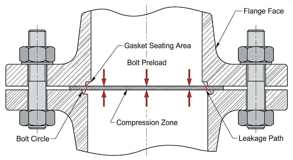
Seal performance depends on the sealing mechanism. Butt-welded joints rely on weld integrity and inspection. Flanged joints rely on gasket compression and bolt load control. Either can be leak-tight; either can leak if the failure mode is ignored.
- Welded fittings: leak-tightness depends on welding procedure, fit-up, and examination/testing requirements (typically managed under a piping code such as ASME B31.3).
- Flanged joints: leak-tightness depends on facing condition, gasket type, bolt grade, lubrication, and tightening sequence—ASME PCC-1 provides BFJA guidance for pressure boundary joints.
- Threaded joints: sealing depends on thread form, sealant, and vibration control; do not assume NPT and ISO 7-1 behave the same.
| Type of Fitting | Strengths | Limitations |
|---|---|---|
| Slip-On Flanges | Simple fit-up, economical in low-to-moderate service where access is good | Performance depends heavily on gasket/bolt-up control and weld details |
| Weld Neck Flanges | Better load path and fatigue resistance at the weld; common for higher-stress services | Higher fabrication effort; alignment and weld quality still govern results |
| Flanged Pipe Fittings | Rapid equipment removal; standardized interfaces | Gasketed joint is a managed leak risk (procedure, inspection, replacement intervals) |
Field example (gasket leak after restart): A Class 300 flange at a pump suction seeped after a hot/cold cycle. The flange faces were acceptable, but bolt load scatter from “by-feel” tightening left the gasket under-compressed in two quadrants. Corrective action: replace the gasket, verify flange parallelism, lubricate consistently, and tighten in a controlled cross-pattern per a documented procedure (industry commonly references ASME PCC-1 guidance for BFJA practices).
Installation & Maintenance Effort
Flanges simplify disassembly; fittings simplify long-term reliability when the line is not meant to be opened. The “effort” depends on what you optimize: initial fabrication time or future access time.
| Aspect | Flanges | Pipe Fittings |
|---|---|---|
| Maintenance Access | Fast access at planned boundaries; no cutting required | Access usually requires cutting/removal unless a service boundary was designed in |
| Disassembly | Bolts + gasket removal; repeatable when procedure is controlled | Often requires cutting, rewelding, re-NDE, and re-testing depending on code |
| Sealing Risk | Managed risk: gasket aging, bolt relaxation, corrosion at faces | Managed risk: weld quality, corrosion allowance, fatigue at geometry changes |
| Inspection | Easy visual checks for external leakage; internal inspection needs opening | Joint inspection depends on NDE plan and access; fewer external leak points |
| Maintenance Costs | Lower cost per “open/close” event if designed as a service interface | Lower recurring cost if no disassembly is required over the equipment lifecycle |
| Operational Flexibility | High: modular swaps and upgrades | Low-to-moderate: changes require fabrication work |
- Flanged connections work best when you plan where maintenance happens (pumps, strainers, control valves, isolation points).
- Pipe fittings work best where you want to reduce gasketed joints and avoid repeated opening/closing events.
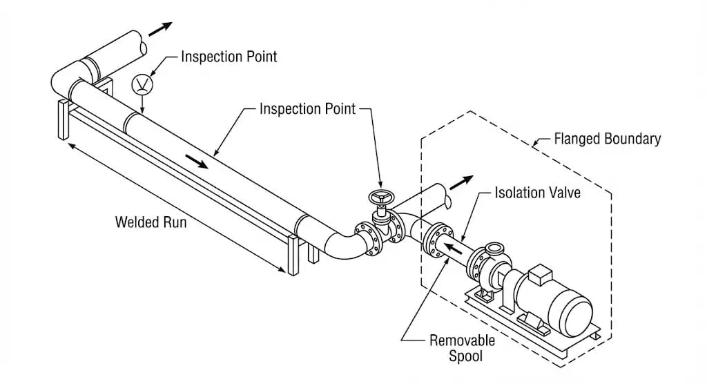
- When you must open a system frequently, consider using a flange boundary and keeping the rest of the run welded.
Flexibility for Future Changes
Flanges offer greater flexibility for future system modifications than permanently welded fittings. The most reliable approach in plant work is to design “maintenance modules” rather than adding flanges everywhere.
| Feature | Flanges | Pipe Fittings |
|---|---|---|
| Detachability | Yes—designed for repeat opening/closing | No—typically permanent once welded |
| Maintenance Access | Good when bolt access and swing space are provided | Limited unless a service boundary exists |
| System Reconfiguration | Supports modular spools and equipment swaps | Reconfiguration requires fabrication work and re-testing |
- You can remove flanged spools for upgrades or rerouting if lifting and bolt access are engineered.
- Blind flanges are commonly used as future tie-in points and test boundaries (select facing and bolt pattern to match the mating flange standard).
- For operational isolation between flanges, use standardized line blanks (e.g., ASME B16.48) rather than improvised plates.
Space & Layout Constraints
Pipe fittings work best in tight spaces and complex layouts, while flanges need clearance for bolting tools and gasket handling. Clearance issues are a leading cause of “design works on paper, fails in the field.”
- Pipe fittings enable compact routing in congested racks and skids.
- Flanges require space for bolts, gasket extraction, tool swing, and safe handling—especially on larger sizes/classes.
- In compact systems, a hybrid approach is common: welded routing with flanged equipment boundaries.
- If you cannot physically torque the bolts correctly, the flange is not “maintainable”—it’s a future leak point.
When comparing Pipe Fittings vs Flanges, confirm bolt access and gasket removal clearance before you lock the layout.
Cost: Initial vs Lifecycle
Cost is driven by how often the joint must be opened and what the outage costs. Welded systems can be economical over the long run if access is not required; flanged systems can be economical if frequent access is required and bolt-up is controlled.
- Initial cost drivers (fittings): welding labor, NDE/testing requirements, and access for fabrication.
- Initial cost drivers (flanges): flange + gasket + bolts, alignment time, and bolt-up procedure time.
- Lifecycle cost drivers (fittings): rework events (cut/re-weld), insulation removal, and retesting.
- Lifecycle cost drivers (flanges): gasket replacement policy, corrosion at faces/bolts, and tightening quality control.
In large projects, the lowest installed cost can become the highest outage cost. Define maintenance boundaries early, then select the connection method that matches your access plan.
Choosing the Right Component: Practical Selection Guide
Maintenance & Accessibility
Choose flanges if you need repeatable access for maintenance. Flanges let you inspect, clean, or replace equipment without cutting. Pipe fittings work best when the joint should not be opened during normal maintenance.
Tip: If the system will be opened on a schedule (filters/strainers, pump maintenance, validation), put a flange boundary there and keep the rest of the run welded.
| Factor | Description |
|---|---|
| Face Type | Facing and gasket design must match (RF/FF/RTJ and gasket standard) to control leakage risk |
| Materials | Match material to corrosion mechanism (chlorides, acids, caustics) and cleaning chemistry |
| Manufacturing Methods | Forgings are commonly selected for pressure boundary integrity; verify heat treatment and traceability requirements |
| Sizes | Confirm bolt access, lifting plan, and removal clearance at the installed location |
| Classification | Use class/PN ratings by temperature for the specific material group, not a single “room temperature” number |
Flexibility & Modularity
Flanges provide superior flexibility when you design them as modular interfaces—not as “extra joints everywhere.” Use flanges to define removable spools and equipment boundaries so upgrades and reroutes stay predictable.
| Advantage | Description |
|---|---|
| Flexibility in Assembly and Maintenance | Modular spools allow equipment swaps and planned tie-ins without cutting |
| Leakage Prevention | Leak tightness is achieved through correct gasket selection and controlled bolt-up procedure (not “tight as possible”) |
| Load Distribution | Correct alignment reduces bending loads that damage gaskets and fatigue welds near equipment nozzles |
Note: If you expect future upgrades, design a spool piece with flanged ends and adequate clearance. Retrofitting flanges later often costs more than doing it right during initial design.
Pressure & Performance
Select the joint type based on the governing failure mode. For many high-pressure applications, welded fittings reduce gasketed leak points. Flanges are still widely used for pressure boundary interfaces, but they require gasket/bolting discipline and correct class selection.
| ASME B16.5 Flange Classes | Maximum Pressure (at 100°F) |
|---|---|
| Class 150 | 285 psi |
| Class 300 | 740 psi |
| Class 400 | 990 psi |
| Class 600 | 1,480 psi |
| Class 900 | 2,220 psi |
| Class 1500 | 3,705 psi |
| Class 2500 | 6,170 psi |
")
The ASME B16.5 class system defines pressure–temperature ratings by material group and temperature. The “at 100°F” values above are commonly referenced summary values; you must still verify the correct rating table for your selected material group and design temperature before you finalize class selection.
Cost & Installation
Pipe fittings can cost more to fabricate (welding + inspection), while flanges can cost more to manage over repeated open/close cycles. If the system is rarely opened, welded routing is often the simplest “lifecycle win.” If the system must be opened on schedule, flanges reduce outage time—if bolt-up is controlled and gasket management is planned.
- Pipe fittings often require skilled welding labor and inspection/testing aligned to your piping code.
- Flanges install faster at equipment boundaries, but sealing performance depends on gasket/bolting procedure.
- For pressure-boundary bolted joints, build a written joint assembly procedure (industry practice often references ASME PCC-1 BFJA guidance).
Tip: Consider both the installation cost and the outage cost. A flange that saves four hours of downtime each maintenance event may pay for itself quickly—provided it does not become a recurring leak point.
Quick Checklist / Decision Flow
Use this checklist to select the right component for your system:
| Criteria | Description |
|---|---|
| Pressure and Temperature | What is the design pressure/temperature? Verify ratings by temperature and material group. |
| Material Compatibility | Is the material compatible with the fluid, cleaning chemistry, and external environment? |
| Flow Requirements | Will the geometry (reducers/elbows/branches) support flow, draining, and venting requirements? |
| Installation Method | Do you have bolt access and tool clearance (for flanges) or welding access and inspection plan (for fittings)? |
| Cost Considerations | What is the true lifecycle cost—fabrication + inspection + downtime + maintenance intervals? |
| Future Expansion | Do you need modular spools/tie-ins, or is the line intended to be permanent? |
Documentation control matters: For regulated or audited projects, define documentation requirements early (heat numbers, material test reports, inspection records, and any certificate types required by contract). Request EN 10204 3.1 documentation when contract/spec requires it, and verify what it covers for your component category.
Summary:
- Choose pipe fittings for permanent, compact routing and to minimize gasketed leak points.
- Choose flanges for planned maintenance boundaries, equipment interfaces, and modular spools.
- Always match joint type to the governing failure mode (vibration, thermal cycling, corrosion, maintenance frequency).
- Control success with standards + procedure: rating tables, material specs, and documented assembly/inspection steps.
Real-World Scenarios
Industrial & Hydraulic Systems
Pipe fittings deliver reliable performance in demanding hydraulic environments when the joint type matches vibration and pressure pulsation. In mobile equipment and hydraulic power units, most “mystery leaks” are not metallurgy problems—they are joint design and assembly problems (thread form, seal method, misalignment, and support).
| Industry | Example Use Case | Benefits |
|---|---|---|
| Construction Machinery | Excavators and loaders using standardized hydraulic fittings for hose connections. | Improved serviceability and fewer leak points when joint type and support are engineered correctly. |
| Agricultural Equipment | Tractors and harvesters connecting hydraulic cylinders and manifolds. | Better uptime when fittings are protected from vibration and contamination ingress. |
| Manufacturing Automation | Factories using fittings for presses and robotic arms. | Reduced unplanned downtime when leak-prone threaded joints are minimized. |
| Mobile Equipment & Vehicles | Heavy-duty vehicles utilizing pressure-rated fittings. | Reliable operation when routing and clamps prevent fatigue at geometry changes. |
| Infrastructure Projects | Hydraulic systems in gates and tunneling equipment. | Predictable maintenance when service boundaries are accessible and standardized. |
Field example (root cause isolation): A hydraulic line showed oil misting after every cold start. Inspection found the leak was not at the pump, but at a reducer where the pipe was acting like a cantilever. Adding a proper support clamp and re-orienting the reducer removed bending load from the joint and stopped the seepage without changing the component class.
Pneumatic & Sanitary Applications
Flanges and quick-connect fittings offer flexibility in pneumatic systems, while hygienic services add cleanability and inspection constraints. In food/bioprocess and pharmaceutical environments, the connection decision is often driven by cleanability, inspectability, surface finish, and documentation—not just pressure class.
- Pneumatic automation uses quick-connect fittings for fast assembly and maintenance access—verify leak rate requirements and vibration conditions.
- Hygienic piping may specify design guidance such as ASME BPE for bioprocessing equipment and sanitary principles such as 3-A criteria (cleanable, inspectable, suitable materials) where applicable.
- When documentation is required (audits, QA), define certificate types and traceability requirements in the purchase specification, not as an afterthought.
Field example (hygiene boundary): A CIP loop had repeated contamination holds at a dead-leg created by a reducer orientation. The fix was not “better material,” but re-orienting geometry for drainability and moving the removable boundary to a location that allowed inspection and cleaning verification.
Maintenance & Upgrades
Flanges simplify maintenance and upgrades when they are placed at the right boundary. The goal is to turn maintenance into a controlled, repeatable bolt-up task—not a cutting/welding task under time pressure. Follow these steps when converting an access point to a flanged boundary:
- Define the maintenance boundary: isolate the equipment spool you expect to remove (pump, strainer, control valve).
- Select flange standard and facing: match the piping class (ASME B16.5 / EN 1092-1 as specified) and select a gasket-compatible facing.
- Specify the joint package: gasket type, bolt/nut grade, lubrication, and tightening method (document the bolt-up sequence).
- Verify alignment and support: reduce bending loads that crush gaskets and fatigue near-nozzle welds.
- Inspect after assembly: check for parallelism, bolt engagement, and external leakage during controlled startup.
Field example (upgrade without rework): A plant needed to add an inline flowmeter but the line was fully welded in a crowded rack. The solution was to install a short removable spool with flanged ends in an accessible bay, then keep the rest welded. Future meter swaps became a scheduled bolt-up task instead of a hot-work outage.
Common Mistakes to Avoid
When you choose between pipe fittings and flanges, most failures trace back to mismatch: mismatch of material to fluid, mismatch of joint type to vibration/maintenance, or mismatch of gasket/bolting procedure to the service. Avoiding these errors improves safety and reliability.
1. Choosing the wrong material:
You must select materials that match your fluid type, chloride level, cleaning chemicals, and operating conditions. Wrong material selection leads to corrosion, leaks, or brittle failure. Stainless steel works for many services, but some environments require higher alloy content or corrosion allowances. Always validate compatibility against the medium and temperature.
2. Ignoring standards and documentation scope:
You need to verify that fittings and flanges meet the standards required by your project and jurisdiction. For example, ASME B16.5 defines dimensions and pressure–temperature ratings for flanges, and ASME B31.3 defines fabrication/inspection/testing requirements for process piping. If you work under EU regulatory scope, the Pressure Equipment Directive (PED) may apply depending on equipment category and conditions.
3. Incorrect sizing and geometry orientation:
Measure and verify sizes and facing compatibility before installation. Common field issues include reducer orientation causing drainability problems, and flange face mismatch (RF vs FF) leading to gasket damage or incomplete compression.
Tip: Before tightening a flange, verify three basics: face compatibility, gasket type matches the face, and bolt access allows a controlled tightening pattern.
4. Overlooking maintenance needs:
If you install permanent joints where you need regular maintenance, you increase downtime and field risk. Design service boundaries intentionally. If you install flanges everywhere without clearance, you create joints you cannot properly assemble or inspect.
5. Treating bolt-up as “tighten until it stops”:
Most flange leaks come from bolt load scatter, poor lubrication control, flange misalignment, and reusing damaged gaskets. Use a documented tightening sequence and inspection points. For pressure-boundary bolted joints, BFJA guidance is commonly referenced from ASME PCC-1.
| Mistake | Impact on System | How to Avoid |
|---|---|---|
| Wrong material | Corrosion, leaks, failure | Match material to fluid, temperature, and cleaning chemistry |
| Ignoring standards | Noncompliance, unreliable performance | Specify standard + rating tables + documentation scope early |
| Incorrect sizing | Leaks, poor performance | Verify size, facing, bolt pattern, and geometry orientation |
| Overlooking maintenance | Higher downtime, higher field risk | Design service boundaries with access clearance |
| Poor flange assembly | Recurring gasket leaks | Use controlled bolt-up procedure and inspection checkpoints |
Pipe fittings work best for permanent, compact layouts. Flanges give you maintainability and modularity when installed with proper access and procedure. Use the table below to guide your decision, then validate against your code/spec and operating conditions:
| Criteria | What to Check |
|---|---|
| Material Compatibility | Match component material to fluid, corrosion mechanism, and temperature |
| Pressure Ratings | Verify rating by temperature and material group (not just “room temp class”) |
| Temperature Conditions | Confirm allowable stress/ratings at design temperature and cycles |
| Design and Operation | Maintenance boundary, drainability, venting, and isolation requirements |
| Safety Information | Confirm standards, traceability, and inspection/testing requirements |
If you want “reliable” to be repeatable, write the specification like an engineer: standard + rating basis + material spec + documentation + assembly/inspection steps.
FAQ
What is the main difference between pipe fittings and flanges?
Pipe fittings typically create permanent routing changes; flanges create a gasketed interface designed to be opened and reassembled. Welded fittings minimize gasketed leak points in permanent layouts. Flanges are a planned access boundary for equipment removal, inspection, and modular upgrades.
| Component | Connection Type | Best Use Case |
|---|---|---|
| Pipe Fittings | Permanent (butt-weld / socket-weld); threaded in limited services | Compact, fixed layouts; minimizing break points |
| Flanges | Detachable (bolted) with gasketed sealing surfaces | Maintenance boundaries; equipment interfaces; modular spools |
When should you choose flanges over pipe fittings?
Choose flanges when you need planned access, modular spools, or operational isolation between flanged joints. Typical triggers:
- You must remove pumps/valves/strainers without cutting the line.
- You expect future tie-ins or equipment upgrades at a known boundary.
- You need a standardized isolation method (e.g., line blanks) for operations.
What materials work best for pipe fittings and flanges?
Material selection must match corrosion mechanism, temperature, and code requirements. Stainless steel (common 304/316 variants) is widely used for corrosion resistance and cleanability, but chloride exposure, temperature, and cleaning chemistry can require upgraded alloys. Carbon and alloy steels are widely used where strength and cost are primary drivers, with corrosion allowance and coating/lining as needed.
Tip: “Stainless” is not a single material. If chlorides or aggressive cleaning chemistry are present, validate pitting/crevice risk and specify the alloy accordingly.
How do you ensure leak-free performance in your system?
Use the right joint type for the service, then execute installation with verifiable checks. Practical controls that prevent most leaks:
- Verify compatibility: flange facing + gasket type + bolt grade + lubrication method.
- Control alignment: reduce bending loads at equipment nozzles and flanged joints.
- Use a documented tightening sequence and inspection checkpoints (especially on pressure-boundary flange joints).
- For welded systems, follow qualified welding procedures and inspection/testing requirements under the governing piping code.
How do you select the right flange class (150/300/600, etc.)?
Select class by design pressure and design temperature for the specific material group—not by a single “room temperature” value. Confirm the pressure–temperature rating tables in the flange standard you are using (e.g., ASME B16.5) and verify the piping code design basis (including corrosion allowance and cyclic conditions).
What are the most common causes of flange leaks after maintenance?
Most recurring flange leaks are assembly-control issues, not “bad gaskets.” Typical causes include bolt load scatter from uncontrolled tightening, reused or damaged gaskets, poor lubrication consistency, flange misalignment, and corrosion or damage on the gasket seating surface.


