
Stopping flange leakage in high-pressure hydrogen service requires more than “tightening bolts.” You need a joint design and assembly method that controls bolt load (not just torque), uses hydrogen-appropriate materials, and applies a gasket system with proven low leakage under cycling.
Hydrogen is challenging to seal because it is a very small, fast-diffusing molecule in many non-metallic materials. A practical way to explain this is kinetic diameter: H2 is typically listed around 2.89 Å versus methane around 3.80 Å, so the sealing system has less margin against micro-paths and permeation through some polymers and composites. If your service is in the “vehicle-fueling class” (often 35 MPa / 70 MPa, i.e., 350 bar / 700 bar), even a micro-leak can become a safety and availability event. For code compliance, the baseline reference in many projects is ASME B31.12 (Hydrogen Piping and Pipelines), with bolted-flange assembly guidance commonly aligned to ASME PCC-1. When you build your approach around bolt load, gasket stress, and verified surfaces, leakage control becomes repeatable—not luck.
Root Causes of Flange Leakage in Hydrogen Service
Flange leakage in high-pressure hydrogen service happens because multiple mechanisms stack up: bolt-load loss (relaxation), uneven gasket stress, surface finish defects that become leak paths, and hydrogen-assisted material damage in susceptible alloys/fasteners.
Unlike natural gas, hydrogen can participate in hydrogen-assisted cracking mechanisms in certain steels and high-strength fasteners, especially when strength/hardness is high or when plating/process control is poor. Separately, at elevated temperature, some carbon steels can suffer High Temperature Hydrogen Attack (HTHA) (typically managed using API RP 941 (Nelson Curves)). In many ambient-temperature high-pressure H2 systems (compressors, storage, dispensing), the most common day-to-day leak drivers are still mechanical: bolt load scatter, flange rotation, gasket seating/creep, and surface damage. Understanding these root causes is central to applying ASME B31.12 correctly and defensibly.
| Cause of Leakage | Description |
|---|---|
| Inadequate Bolt Preload | Low initial bolt load cannot maintain gasket stress against internal pressure. In hydrogen, “borderline” preload tends to show up as micro-leaks first, then grows with cycles. |
| Improper Bolt Tightening Sequence | Uneven tightening causes local gasket over-compression and under-compression. Under-compressed sectors become leak paths during pressurization and thermal cycling. |
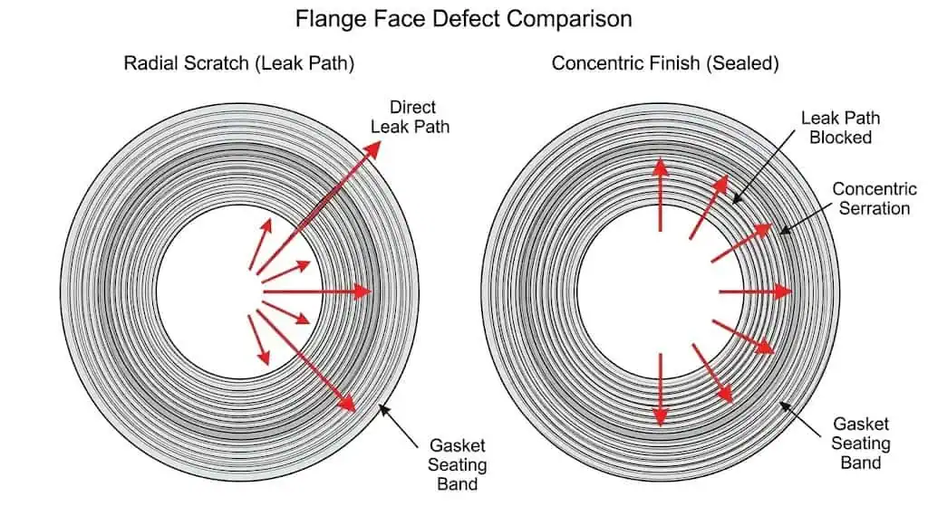
| Poor Contact Surface Quality | Radial scratches, dents, or an out-of-spec finish create direct leak channels. For many ASME B16.5 raised faces with spiral-wound gaskets, typical stock finish is in the 125–250 µin Ra range (roughly 3–6 µm Ra) when properly machined and undamaged. |
| Hydrogen-Assisted Damage (HE Risk in Susceptible Parts) | High-strength/hard fasteners and certain steels are more susceptible. Hydrogen effects increase with strength/hardness and with stress concentration at threads or under nut bearing surfaces. |
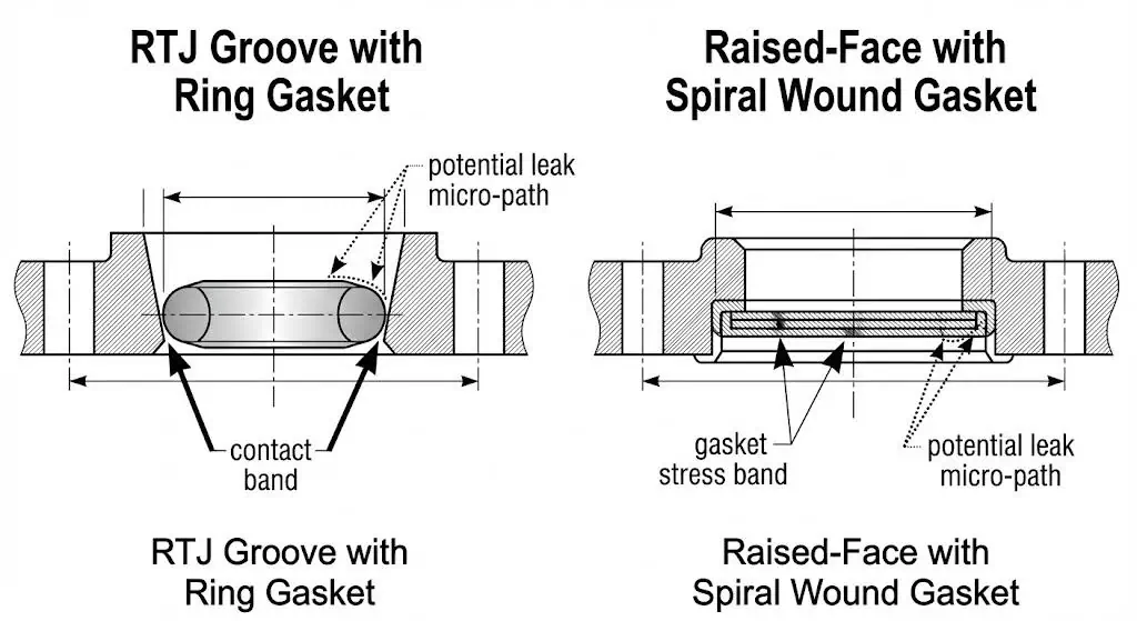
| Gasket Construction Not Matched to H2 Service | Some non-metallic/composite systems can allow higher permeation or interface leakage under cycling. For very high pressure, metal-to-metal style sealing (e.g., RTJ) is often selected; otherwise use gasket constructions with strong recovery and proven leakage performance under cycling. |
| Bolt Surface Condition & Friction Scatter | Dirty threads, galling, mixed lubrication, or re-used nuts change friction. Torque then becomes a poor proxy for bolt load, creating clamp-load scatter and leak risk. |
| Misalignment / Flange Rotation | Angular misalignment and piping loads bend the joint, unloading the gasket on one side. This is a frequent “mystery leak” driver after maintenance or pipe modification. |
Bolt Preload & Relaxation
Incorrect bolt preload is a leading cause of flange leakage.
In high-pressure service, bolts commonly lose effective clamp load early because the gasket seats (embedment) and relaxes. That bolt-load loss can happen within hours to the first day after assembly, and then again after the first thermal cycle. ASME PCC-1 treats bolted flange joints as a system: flange stiffness, gasket type, lubrication condition, and tightening method all matter.
Engineering control that actually works: treat torque as an indirect method. For critical hydrogen joints, reduce scatter by standardizing lubricant, nut/washer condition, and tool calibration, and consider bolt-load verification (bolt elongation, ultrasonic measurement) when feasible. If you must use torque, document the assumed friction factor and keep it consistent across the joint.
Field example (representative): A Class 900 raised-face joint passed a soap test at low pressure but developed a micro-leak after first pressurization and cooldown. The root cause was mixed lubrication: half the studs were lightly oiled, half were dry from storage. Torque values were identical, but clamp load was not. The corrective action was a controlled clean/lube procedure (same lubricant, same washer type), a multi-pass tightening sequence, and a torque check pass after the first temperature stabilization.
Improper Tightening Sequence

Improper tightening sequence leads to uneven gasket compression and flange leakage.
You should tighten bolts in a Legacy Star Pattern (Cross Pattern) to distribute gasket stress. For most joints, a multi-pass approach is more stable than a single “final torque” pass. A common controlled method (aligned with industry practice reflected in ASME PCC-1) is: ~30% → ~60% → 100% of target torque in cross pattern, followed by a circular check pass at 100% until nuts stop turning.
Practical note for hydrogen: if a joint leaks, “random retightening” often makes it worse by creating localized gasket crush. Retightening should be controlled, patterned, and documented—or the joint should be opened and corrected (alignment, surface, gasket damage) rather than forced.
Surface Finish Requirements
Poor surface finish or damage increases the risk of fugitive emissions.
For many ASME B16.5 raised-face applications using spiral-wound gaskets, the commonly referenced stock finish range is 125–250 µin Ra (about 3–6 µm Ra). What matters most in hydrogen is not “polish,” but no radial scratches, no dents, and a consistent machining pattern. A concentric serrated finish is often preferred when you are trying to avoid “straight-through” leak channels. If your face has radial scoring, do not “torque your way out” of it—re-machine or replace the flange.
Field example (representative): A joint repeatedly leaked at the same clock position despite gasket replacement. The actual driver was a shallow radial tool mark crossing the raised face. The fix was a controlled re-facing to the correct roughness range and a final inspection using lighting at a low angle to reveal radial features. The repeat leak stopped without increasing torque.
Corrosion & Hydrogen Attack
Corrosion and hydrogen-related damage can weaken sealing surfaces and create new leak paths.
Two different issues are often mixed up:
- Hydrogen embrittlement / hydrogen-assisted cracking: a risk for susceptible materials and high-strength fasteners under stress, often managed by controlling material strength/hardness and by selecting hydrogen-compatible alloys.
- High Temperature Hydrogen Attack (HTHA): a high-temperature degradation mechanism in some steels, typically managed using API RP 941 guidance when you are in elevated-temperature hydrogen service.
At the flange face level, corrosion pitting and crevice corrosion around the gasket contact band can “print” leak paths into the joint. In chloride-bearing environments, material selection and surface condition control matter as much as torque.
Gasket Selection Errors
Choosing a gasket system that is not matched to pressure, cycling, and leakage expectation is a common failure mode.
Hydrogen service frequently involves pressure cycling and thermal effects. That means you need (1) a gasket with sufficient recovery and stability, and (2) a flange face type and finish that the gasket was designed for. For very high pressure, RTJ joints are often selected because the sealing is metal-to-metal at the ring contact. For raised-face joints, spiral-wound gaskets with correct centering/inner rings and controlled assembly can perform well when the joint is stiff and aligned.
Selection tip: if you are designing for defined leak tightness performance, European practice often references calculation/parameter frameworks like EN 1591-1 (flange joint calculation for strength and leak-tightness) and EN 13555 (gasket parameters and test procedures). Even if your project is ASME-based, the logic is useful: make gasket performance a measurable input, not a guess.
| Gasket / Joint Option | Where it is typically used (engineering view) |
|---|---|
| RTJ (Ring Type Joint) | Very high pressure gas service and high consequence joints where metal-to-metal ring seating is preferred. Requires correct groove condition and ring material selection. |
| Spiral Wound (with inner ring as applicable) | Common for raised-face flanges when assembly control is strong and flange stiffness is adequate. Sensitive to uneven loading and face damage. |
| Metal jacketed / Kammprofile (grooved metal core) | Used when you need improved recovery/handling versus some spiral constructions, often with defined gasket parameters and controlled compression. |
Contamination
Contamination on bolts, flanges, or gaskets can create flange leakage over time.
Hydrogen joints expose weaknesses quickly because torque scatter turns into clamp-load scatter. Dirt in threads, reused damaged nuts, inconsistent lubricant, and galling all change friction. That means torque values no longer map to the bolt load you think you applied. Clean threads, stable lubrication, and consistent washers are “small” steps that remove large uncertainty.
Field example (representative): A maintenance team replaced a gasket but reused nuts that had thread pickup. Torque was reached early due to high friction, leaving low bolt load. The leak appeared immediately on pressurization. Corrective actions: replace compromised nuts, chase/clean studs, apply controlled lubricant, then tighten using multi-pass cross pattern and a final check pass.
Fact Check: Hydrogen is flammable across a wide range in air (commonly cited around 4% to 75% by volume). Treat even “micro-leaks” as a serious hazard and verify with suitable H2 detection methods.
High-Pressure Hydrogen Sealing Solutions
Material Selection: Why 316L Matters
For many gaseous hydrogen environments, austenitic stainless steels such as 316/316L are commonly treated as a strong baseline for hydrogen compatibility, but they are not “magic.” Selection still depends on pressure, temperature, strength level, and fabrication state.
A key reason 316/316L is widely used is that austenitic stainless steels can show better resistance to hydrogen-assisted damage than many higher-strength steels under comparable conditions. Hydrogen compatibility references used in industry emphasize that hydrogen effects are highly sensitive to material condition (cold work, sensitization, strength level) and environment (pressure and temperature). In procurement terms: require traceable material test reports, verify heat treatment condition, and avoid unnecessary cold work in critical areas.
Fastener reality check: hydrogen embrittlement risk increases with fastener hardness/strength. If your bolting strategy relies on high hardness, you must manage that risk explicitly (material choice, process controls, coating strategy, and inspection). This is not a flange-only issue; it is a joint integrity issue.
Sunhy’s stainless steel flanges can be specified in solution-annealed 316L forgings to reduce residual stress and stabilize corrosion performance. For hydrogen projects, treat this as a documentation requirement: request heat treatment records and verify dimensional and facing controls as part of your QA package.
Advanced Gasket Technologies
For high-pressure hydrogen, prioritize gasket systems that maintain gasket stress under cycling and that have a defensible leakage performance basis—calculation parameters, qualification data, or both.
For pressures above 100 bar, RTJ joints are often selected when the design intent is to reduce permeation paths and increase robustness to cycling. For raised-face joints, spiral-wound or grooved-metal-core style gaskets can work well when flange stiffness, alignment, and assembly procedure are controlled. If your project requires quantified leak performance, use helium or suitable detection methods during commissioning and consider referencing parameter-based frameworks (EN 1591-1 / EN 13555) in addition to ASME practices.
| Verification Item | What to request / verify (practical QA) |
|---|---|
| Gasket suitability | Pressure class and facing type match, material compatibility statement for H2 service, and handling/storage requirements. |
| Leakage basis | Gasket parameters (where available), past qualification evidence, or a defined commissioning leak test method and acceptance criteria. |
| Joint stiffness & alignment | Check flange parallelism, pipe strain at the joint, and whether the assembly is prone to rotation/unloading under load. |
Installation Best Practices
Follow strict installation steps to maximize flange sealing technology and prevent leaks.
- Confirm the flange facing type and finish match the gasket design intent (do not mix “looks similar” components).
- Verify alignment: flange faces should be parallel; avoid pulling misaligned pipe into place with bolts.
- Standardize bolt lubrication and washer/nut condition to reduce torque-to-load scatter; document the lubricant used.
- Clean all parts before assembly. Remove rust, dirt, oil, and any gasket residue; inspect for dents and radial scratches.
- Center the gasket and keep it flat; avoid sliding it across the raised face once positioned.
- Use a controlled tightening procedure (cross-pattern multi-pass + final circular check pass) aligned with industry guidance such as ASME PCC-1.
Real-World Case Study: Thermal Cycling Leakage
Case background (representative): A 70 MPa (700 bar) hydrogen compressor discharge line experienced recurring leakage at a flanged joint after maintenance. The joint used a raised-face flange with a gasket system that had limited recovery under cycling, and the tightening method was a single-pass “final torque” approach.
The problem: Rapid temperature changes during compression and cooldown caused differential expansion and bolt-load loss. The joint also showed signs of angular misalignment (pipe strain), which unloaded one sector of the gasket band. The leak signature was intermittent: it could disappear warm and return cold, which is typical of gasket stress instability rather than a simple “loose bolt.”
The solution: The corrective work focused on joint mechanics, not higher torque: (1) flange alignment corrected so bolts were not used to “pull” the pipe, (2) a gasket system selected for better recovery and stability for the facing type, (3) a controlled multi-pass cross-pattern tightening procedure with a final check pass, and (4) bolt condition and lubrication standardized. In cycling-prone joints, some projects also use load-stabilizing strategies (e.g., disc spring stacks) where appropriate, but the baseline requirement is always correct alignment + controlled assembly.
Result (engineering expectation): When clamp-load scatter is reduced and gasket stress is stabilized, commissioning leak checks typically show a repeatable improvement. If a quantified leakage class is required, the project should define a test method and acceptance criteria and capture the results as part of the QA record.
Prevention and Maintenance
Routine Inspection

You can prevent most flange leaks by inspecting your system on a regular schedule using H2 detectors.
Hydrogen is odorless and colorless, so visual checks alone are not enough. Use portable hydrogen detectors (“sniffers”) or suitable methods such as ultrasonic detection for high-pressure leak signatures. In higher consequence areas, define an inspection interval based on cycling severity and exposure risk (near people, ignition sources, enclosed spaces). If you find a leak, treat the response as a controlled maintenance activity—do not rely on random bolt tightening as the primary fix.
Inspection Checklist:
- Check for visible corrosion, fretting marks, or moisture/ice formation near the joint (a clue in expansion/cooling zones).
- Use a handheld hydrogen gas detector appropriate for the area classification.
- Listen for ultrasonic noise (high-pressure leaks often generate high-frequency sound).
- Verify bolt condition and look for evidence of rotation/loosening; document findings before any adjustment.
- Record operating context (pressure/temperature at the time) so the leak can be tied to cycling conditions.
Staff Training
You stop leaks by training your staff to spot and fix problems early.
Train bolting personnel on controlled flange assembly: alignment checks, gasket handling, lubrication discipline, tool calibration, and patterned multi-pass tightening. Emphasize that “torque achieved” does not automatically mean “bolt load achieved.” In critical service, require competency-based qualification aligned to recognized practices (ASME PCC-1 training programs are one route; some EU projects also reference competency frameworks such as EN 1591-4 for critical assemblies).
Documentation
You reduce leaks by keeping good records of every inspection and repair.
Document flange joint history like you would any pressure boundary: gasket type/lot, flange facing condition, bolt material and lubrication used, tightening method (pattern + passes), tool calibration status, and commissioning leak check method/results. Records help you separate a design limitation from an assembly variance, and they let suppliers support you with evidence rather than guesswork.
| Date | Location | Leak Found | Action Taken | Staff Name |
|---|---|---|---|---|
| 2024-05-01 | Flange #12 | Yes (Micro) | Opened joint, corrected alignment, replaced gasket, controlled multi-pass tightening + check pass | J. Smith |
| 2024-05-10 | Flange #7 | No | Routine detector check + visual/ultrasonic screening | L. Brown |
Note: Reliable suppliers help, but the joint still fails or succeeds on: correct specification, correct surface condition, correct assembly, and correct verification.
You can stop flange leakage in high-pressure hydrogen service by picking the right materials, assembling to a controlled bolt-load method, and verifying performance after cycling.
- Specify hydrogen-appropriate materials and document material condition (heat treatment, strength level, traceability).
- Match gasket type to pressure, facing, and cycling; avoid “equivalent” substitutions without evidence.
- Control alignment and tightening sequence; reduce torque scatter by standardizing lubrication and hardware condition.
- Inspect with suitable H2 detection methods and record results tied to operating conditions.
For safety-critical hydrogen systems, treat every leaking flange as a root-cause problem: verify alignment, surface condition, gasket selection, and bolt-load method before you change the torque target.
FAQ
What is the best gasket for high-pressure hydrogen service?
There is no single “best” gasket; the best choice depends on pressure class, facing type, cycling, and the leak tightness expectation.
For very high pressure gas service, RTJ joints are often selected because the sealing is at a metal ring contact. For raised-face joints, spiral-wound or grooved-metal-core style gaskets can work well when flange stiffness, alignment, and controlled assembly are in place. Always match gasket construction to flange facing and pressure rating, and define a verification method at commissioning (detector method + acceptance criteria).
How do you prevent gasket failure during installation?
Prevent gasket failure by controlling alignment, surface condition, and bolt-load method—not by “more torque.”
Clean and inspect flange faces (no radial scratches, dents, or residue). Verify flange parallelism and avoid pulling misaligned pipe into place with bolts. Tighten in a cross-pattern multi-pass method (e.g., ~30% → ~60% → 100%), then perform a circular check pass. Use calibrated tools and consistent lubrication so torque is a stable proxy for bolt load.
Why do gaskets leak in hydrogen systems?
Hydrogen leaks often come from bolt-load loss, uneven gasket stress, and small leak paths that would be “forgiving” in larger-molecule gases.
Hydrogen’s small molecular size and its behavior in some sealing materials reduce margin. Add pressure/thermal cycling and torque scatter, and the joint can fall below the gasket stress needed to stay tight. In practice, most persistent leaks trace back to: (1) alignment/rotation, (2) face damage, (3) gasket mismatch, or (4) uncontrolled tightening.
How often should you inspect gaskets in hydrogen service?
Inspect based on risk: cycling severity, pressure level, and consequence of release.
A common engineering interval is every 3–6 months for routine screening, and additionally after major thermal/pressure cycling events or maintenance. Use H2 detection methods rather than visual checks alone, and document operating conditions at the time of inspection so intermittent cycling-related leaks can be diagnosed.
Can you reuse a gasket after disassembly?
In critical hydrogen service, treat gaskets as single-use.
Once compressed, many gasket systems lose recovery or show imprinting damage that changes leakage behavior. Reuse increases uncertainty and makes root-cause diagnosis harder. If the joint must be reopened, replace the gasket and re-verify surface condition and alignment.
Do you need to re-torque after pressurization or the first thermal cycle?
Sometimes—but only as part of a defined procedure.
Gasket seating/relaxation can reduce bolt load after the first stabilization period. If your procedure allows a re-check, do it under controlled conditions (patterned, documented, and within design limits). If a leak persists, opening and correcting the joint (alignment, face condition, gasket damage) is usually more reliable than repeatedly increasing torque.


