
A flange is a pressure-boundary component used to connect pipes, valves, pumps, and equipment in a piping system. In real plant service, a flange joint is not simply “two parts bolted together.” Long-term sealing depends on flange design, facing style, gasket selection, bolt preload, alignment quality, support condition, and how the joint behaves under vibration, pressure fluctuation, and thermal cycling.
If you are comparing the main types of industrial flanges, the key question is not only “what flange is this?” but also “what service condition is this joint expected to survive?” That is what decides whether the connection remains stable, maintainable, and leak-free over time.
Quick Answer: Which Flange Type Is Usually Best?
- Best for high pressure / thermal cycling: Weld neck flange
- Best for easy fit-up in utility service: Slip-on flange
- Best for small-bore higher pressure piping: Socket weld flange
- Best for line closure and isolation: Blind flange
- Best for removable spools and maintenance access: Lap joint flange with stub end
- Best where no hot work is preferred: Threaded flange, with vibration limits checked
In practical selection, most engineers narrow flange type using five variables:
- Pressure and temperature envelope
- External loads, vibration, and thermal movement
- Maintenance frequency and dismantling needs
- Corrosion mechanism and material strategy
- Applicable dimensional standard and project code
You will most often encounter these flange types in plant piping, equipment nozzles, skid packages, and maintenance spools:
- Weld neck flanges
- Slip-on flanges
- Socket weld flanges
- Threaded flanges
- Blind flanges
- Lap joint flanges with stub ends
- Long weld neck and custom-engineered flanges
For most ASME projects, the governing dimensional references are ASME B16.5 for common sizes and ASME B16.47 for large-diameter flanges. The final joint still has to comply with the relevant piping code, commonly ASME B31.3 for process piping.
What Are Flanges in Piping?
Flange Definition
A flange creates a detachable joint between piping components. Unlike a permanent welded connection, a flange assembly lets you open the system for inspection, replacement, cleaning, hydrotest isolation, or equipment removal. That is why flanges remain essential wherever a line will be maintained during its service life.
Important: “Same size” is not enough. If two flanges come from different standard systems, the bolt circle, thickness, facing geometry, and drilling pattern may not match.
In engineering practice, a flange joint only performs well when all of these are compatible:
- Flange standard and pressure class
- Facing type and gasket design
- Bolting material and preload method
- Pipe alignment and support condition
- Fluid, corrosion, and temperature requirements
What Flanges Actually Do in a Piping System
Flanges are used for much more than connection. In a well-designed piping system, they also support safe maintenance planning, predictable sealing, accurate equipment tie-in, and controlled isolation of sections during operation or shutdown.
- Connection: joining pipe, valves, pumps, strainers, meters, and vessels
- Containment: holding system pressure safely within the joint envelope
- Sealing: compressing the gasket correctly across the seating area
- Accessibility: allowing future dismantling without cutting pipe
- Alignment: helping maintain proper orientation between connected components
- Isolation: closing off equipment or line ends using blind flanges or spectacle blinds
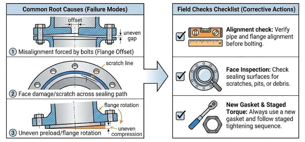
Field lesson: many flange leaks are not caused by “bad gaskets.” The real causes are often poor alignment, wrong facing/gasket combinations, uneven bolt load, bent spools, damaged sealing surfaces, or pipe supports that allow unintended external load into the joint.
Main Types of Flanges
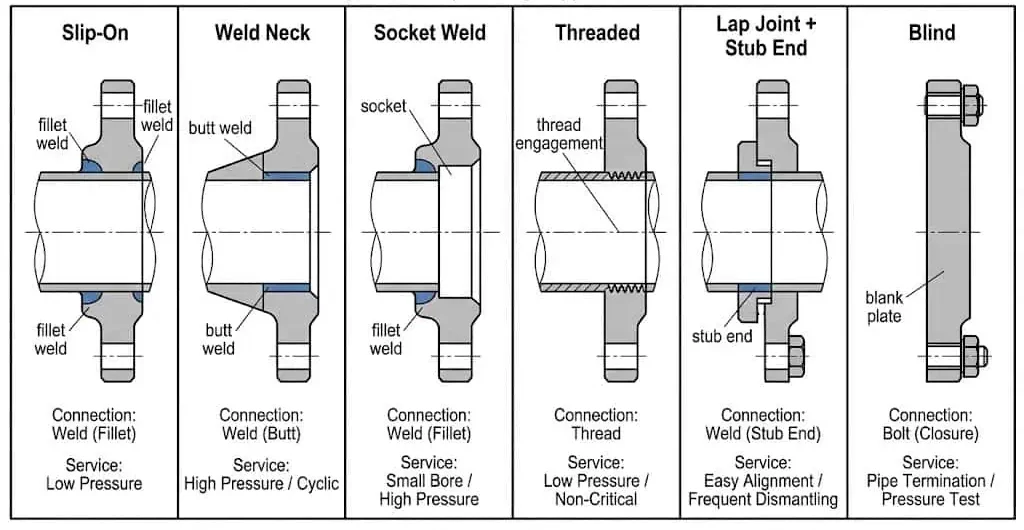
Weld Neck Flange
Weld neck flanges are generally preferred for higher pressure, higher temperature, and fatigue-sensitive service. Their long tapered hub improves stress transfer between the pipe and flange and reduces stress concentration at the weld transition. This is why they are widely used in oil & gas, refining, chemical processing, power generation, and marine systems.
- Best fit for cyclic loads, thermal movement, and higher bending stress
- Requires butt welding and better fit-up control
- Often preferred near pumps, compressors, and hot service lines
Usually the wrong choice when: budget and fabrication simplicity matter more than fatigue resistance, or the service is a straightforward low-pressure utility line.
For a direct comparison, see this internal slip-on vs weld neck flange guide.
Slip-On Flange
Slip-on flanges are popular for utility service and cost-sensitive installations where fit-up speed matters. The pipe slips into the flange bore and is typically fillet welded on the inside and outside. This makes shop fit-up easier, but the joint is generally less fatigue-tolerant than a weld neck under severe cyclic or high-vibration conditions.
- Easy alignment and fast fabrication
- Often used on low-to-moderate pressure utility lines
- Common in water treatment, chilled water, general plant service, and stable-load piping
Usually the wrong choice when: the joint sits close to rotating equipment, sees cyclic bending, or may be exposed to vibration beyond the original design assumption.
Socket Weld Flange
Socket weld flanges are commonly used on smaller bore, higher pressure piping. The pipe is inserted into the socket and fillet welded around the outside. This design can provide a compact and strong joint for small-bore systems such as instrumentation lines, hydraulic service, sampling connections, and certain steam applications.
- Suitable for small sizes where compactness matters
- Frequently selected for higher-pressure small-bore service
- Requires controlled gap and welding procedure to avoid restraint issues
Usually the wrong choice when: the system is large bore, easy field dismantling is required, or the project prefers fully butt-welded transitions for consistency.
Blind Flange
Blind flanges are used to terminate, isolate, or temporarily close a line or nozzle. Because there is no center bore, a blind flange acts as a full pressure boundary. In shutdowns, hydrotests, commissioning, and equipment isolation, blind flanges should be treated as real pressure components rather than “temporary covers.”
- Used for maintenance isolation and future system expansion points
- Common on vessel nozzles, spare branches, and test boundaries
- Requires the same attention to gasket, bolting, and alignment as any other pressure joint
Usually the wrong choice when: the line needs regular through-flow or the closure point should instead be handled by a removable spool or spectacle blind system.
Lap Joint Flange
Lap joint flanges are selected for maintenance access, bolt-hole alignment flexibility, and alloy cost strategy. A lap joint assembly consists of a loose backing flange plus a butt-welded stub end. Because the backing flange rotates, bolt alignment is easier during fit-up and future dismantling is faster.
- Well suited for removable spools, filters, exchangers, skid tie-ins, and maintenance points
- Useful when alloy cost should be concentrated at the wetted stub end
- Helps where field bolt-hole alignment is otherwise difficult
Usually the wrong choice when: external bending loads are high, the spool is poorly supported, or the joint is expected to act like a rigid structural connection.
Threaded Flange
Threaded flanges avoid welding and are typically used on smaller size, lower risk, or no-hot-work applications. They can be assembled quickly, but performance is highly sensitive to thread fit, sealant compatibility, support, and vibration. In high-vibration zones, threaded joints often become long-term leak risks.
- Useful where welding is restricted or undesirable
- Common on smaller bore systems and temporary or accessible service
- Should be reviewed carefully when gas service or vibration is involved
Usually the wrong choice when: the joint is close to cyclic vibration, thread leakage paths are unacceptable, or the system needs a higher-integrity welded transition.
Quick Comparison Table
| Flange Type | Main Strength | Typical Best Use | Main Limitation |
|---|---|---|---|
| Weld Neck | Best stress distribution | High pressure, thermal cycling, fatigue-sensitive service | Higher fabrication cost |
| Slip-On | Fast fit-up and low cost | Utility and stable-load piping | Less fatigue-tolerant |
| Socket Weld | Compact high-pressure small-bore joint | Instrumentation and small-bore pressure service | Limited to smaller sizes |
| Blind | Positive isolation | Shutdown, hydrotest, nozzle closure | No flow path |
| Lap Joint | Easy alignment and dismantling | Maintenance points and alloy strategy | Lower rigidity under bending |
| Threaded | No welding required | Small-bore and restricted hot work areas | Sensitive to vibration and thread leakage paths |
Representative Industry Scenarios & Engineering Lessons
The best technical content should show how selection works in realistic service, not only in definitions. The examples below are representative engineering scenarios often seen in plant piping, utility systems, and skid packages.
Scenario 1: Cooling Water Header Near a Pump
Typical issue: A low-pressure cooling water system starts weeping after a pump upgrade introduces more vibration than expected.
Common cause: Slip-on flanges were acceptable for original utility duty, but misalignment, weak supports, and uneven bolt-up now allow flange rotation and gasket unloading.
Engineering takeaway: In vibration-sensitive locations, weld neck flanges or stronger support control are often the better long-term choice than simply retorquing the same joint.
Scenario 2: Heat Exchanger Spool Removed During Shutdowns
Typical issue: Maintenance teams need to remove a spool repeatedly for cleaning and inspection, but welded joints create too much hot work and reassembly delay.
Common cause: The original connection was selected only for initial fabrication convenience, not for repeated dismantling.
Engineering takeaway: A lap joint flange with stub end is often a better fit where frequent removal, bolt-hole alignment flexibility, and maintenance speed matter.
Scenario 3: Hydrotest Boundary on a New Line
Typical issue: A test boundary leaks during pressurization even though the blind flange class appears correct.
Common cause: Poor face condition, reused gasket, or uneven bolt load caused by rushed tightening sequence.
Engineering takeaway: A blind flange should be treated as a full pressure joint. Class alone does not guarantee sealing if assembly discipline is poor.
Scenario 4: Small-Bore Instrument Air in a No-Hot-Work Area
Typical issue: A threaded joint begins weeping after startup in a skid area with repeated vibration.
Common cause: Threaded connection was chosen for fast installation, but thread engagement, sealant, or support was not robust enough for the vibration level.
Engineering takeaway: Threaded flanges are useful in restricted hot-work situations, but vibration and leakage path risk must be reviewed before treating them as a permanent best option.
Expert recommendation: choose the flange based on the joint’s real duty over its service life, not only the easiest shop fabrication route on day one.
Flange Facing Types
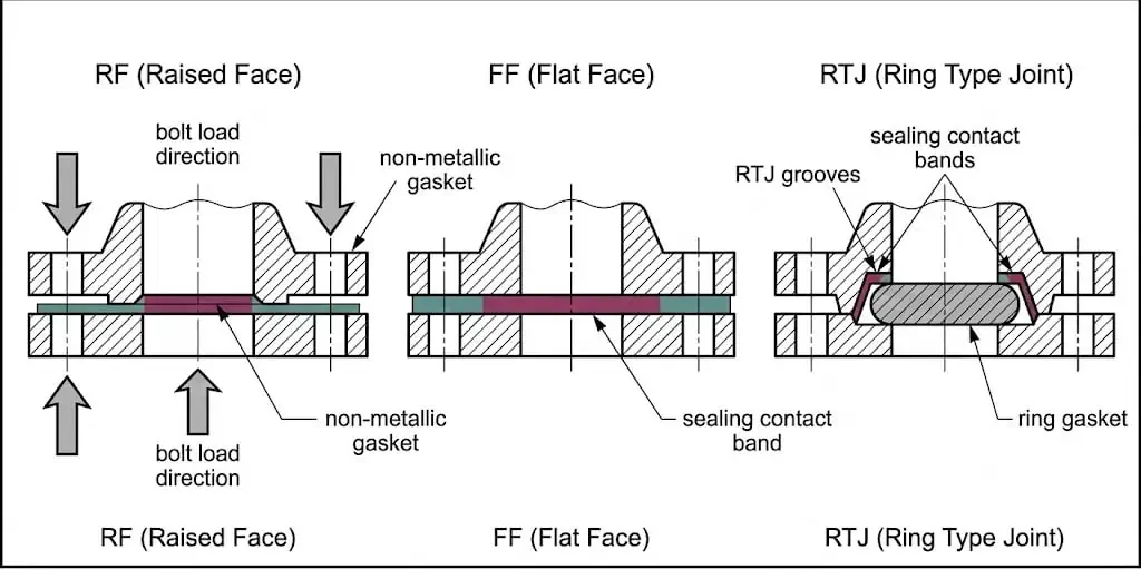
The flange face controls how gasket stress is created and maintained. Even a correctly rated flange can leak if the face style does not match the gasket design or if two incompatible facings are assembled together. For a dedicated explanation, see this internal RF vs FF flange face comparison.
Raised Face (RF)
Raised face is the most common industrial facing. It concentrates gasket load on a smaller seating area and is widely used in ASME process piping.
Flat Face (FF)
Flat face is typically used where the mating equipment or piping is brittle or lower pressure. It is common on cast iron equipment and some waterworks applications.
Ring Type Joint (RTJ)
RTJ is used for severe pressure and temperature service. It relies on a metal ring gasket and correctly machined grooves, so installation accuracy is critical.
Do not mix incompatible faces. RF-to-FF and RTJ mismatches are common causes of joint damage, poor gasket loading, and repeat leakage.
Flange Materials in Piping
Stainless Steel Flanges
Stainless steel remains the default choice for many corrosive and clean-service applications. Material selection should follow the corrosion mechanism, not only general “stainless vs carbon steel” thinking. If chlorides, washdown chemicals, food contact, or offshore exposure are involved, material choice becomes a design decision rather than a purchasing decision.
For common grades, see this internal 304/304L and 316/316L stainless material guide.
Carbon Steel and Alloy Steel
Carbon steel and alloy steel flanges are widely used where strength and cost control matter. Carbon steel is common in oil, gas, water, and general industrial systems. Alloy steels are selected for elevated temperature, creep resistance, or demanding refinery and power applications.
Special Materials and Custom Flanges
When the service is too demanding for standard catalog options, custom flange engineering becomes necessary. This includes non-standard thickness, special facings, cladding, overlay, unusual materials, and custom dimensions. For these cases, use custom flange manufacturing rather than forcing a standard part into a non-standard duty.
| Material Family | Typical Strength | Typical Use |
|---|---|---|
| Carbon Steel | Cost-effective general service strength | Water, oil, gas, utility piping |
| Stainless Steel | Corrosion resistance | Chemical, food, offshore, washdown, general corrosive service |
| Alloy Steel | High temperature / higher strength | Power, refining, elevated-temperature service |
| Nickel / Special Alloys | Extreme corrosion or temperature resistance | Harsh chemical and severe specialty service |
| Non-Metallic | Lightweight corrosion resistance | Low-pressure chemical and water applications |
Gasket Materials and Flange Selection
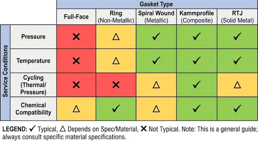
Gasket choice is part of flange selection, not a separate afterthought. The best flange design still fails if the gasket material, facing style, or seating stress is wrong for the fluid and operating cycle. For a practical zero-leak workflow, review this internal flange assembly guide.
Common gasket categories include:
- Full-face gaskets for lower pressure systems
- Ring gaskets for raised face applications
- Spiral wound gaskets for higher pressure and temperature
- Kammprofile gaskets for demanding cycling conditions
- RTJ ring gaskets for severe service
Minimum bolt-up checklist:
- Clean both flange faces completely
- Confirm gasket type, size, and centering
- Lubricate studs and nuts as specified
- Tighten in a cross pattern using multiple increments
- Never use torque to force misaligned flanges together
Best practice: if a joint has already leaked, do not assume “more torque” is the solution. Investigate face condition, alignment, support, gasket compatibility, and preload uniformity first.
How to Choose the Right Flange Type
Selection Criteria
You should match the joint design to the duty, not the other way around. In most projects, the right flange is selected by balancing pressure, temperature, maintenance strategy, available space, fabrication method, material compatibility, and lifecycle cost.
- Define the service class: pressure, temperature, medium, and criticality
- Check external loads: vibration, valve weight, thermal growth, unsupported spans
- Match the facing and gasket: RF, FF, RTJ, or other special face
- Confirm the material system: corrosion, alloy strategy, compliance requirements
- Review maintenance needs: whether the joint will be opened again
- Verify the standard: ASME B16.5, B16.47, DIN, JIS, or other project requirement
- Check manufacturability and lead time: standard vs custom flange route
Common Mistakes
- Choosing by price only and ignoring service class
- Using incompatible flange faces
- Forcing misalignment with bolts
- Reusing damaged or compressed gaskets
- Ignoring pipe supports near the joint
- Ordering the correct NPS but the wrong standard family
Decision Table
| Condition | Prefer | Main Reason |
|---|---|---|
| High pressure / thermal cycling / fatigue risk | Weld Neck | Better stress distribution at the transition |
| Low-pressure utility piping and fast field fit-up | Slip-On | Economical and easy to align |
| Small-bore higher pressure service | Socket Weld | Compact high-strength small-bore connection |
| Frequent dismantling or alloy stub-end strategy | Lap Joint | Easy alignment and lower dismantling cost |
| No hot work or quick removable small-bore connection | Threaded | No welding required |
| Line end isolation or hydrotest boundary | Blind | Positive closure of the flow path |
Official Standards References
For specification and compliance work, use official sources rather than distributor summaries:
- ASME B16.5 official standard page
- ASME B16.47 official standard page
- ASME B31.3 official code page
- ASTM A182/A182M official specification page
Need Help Choosing the Right Flange for Your Project?
Send your size, pressure class, material, facing, and application details. Sunhy can help you shortlist a practical flange design, review whether you need a standard or custom solution, and support RFQ preparation for stainless, alloy, or special-duty flange projects.
- ASME B16.5 and B16.47 standard flanges
- Slip-on, weld neck, blind, threaded, socket weld, and lap joint designs
- Custom flange manufacturing for drawings, special materials, and non-standard dimensions
FAQ
What are the main types of flanges used in piping systems?
The most common piping flange types are weld neck, slip-on, socket weld, threaded, blind, and lap joint.
Each type is selected for a different balance of strength, fabrication method, maintenance access, and cost.
Which flange is usually best for high-pressure service?
Weld neck flanges are typically preferred for high-pressure, high-temperature, and fatigue-sensitive applications.
The tapered hub improves stress distribution and makes the joint more reliable under demanding service conditions.
When should you use a lap joint flange instead of a slip-on flange?
Use a lap joint flange when frequent dismantling, bolt-hole alignment flexibility, or alloy-cost control matters.
Slip-on flanges are better suited to stable-load welded utility service where the joint is unlikely to be reopened.
Can you mix raised face and flat face flanges in one joint?
No, you should not mix incompatible flange faces.
RF-to-FF mismatch can create uneven gasket loading, sealing problems, or damage to brittle equipment. RTJ flanges also require matching grooves and the correct ring gasket.
Can you reuse a gasket after opening a flange?
No. Gaskets should normally be replaced after disassembly.
Once compressed and exposed to service, a gasket may lose thickness recovery, sealing stress, and surface integrity.
How do you choose the correct flange material?
Choose flange material based on fluid chemistry, temperature, environment, and compliance requirements.
Stainless steel is common for corrosion resistance, carbon steel for general service, and special alloys for severe chemical or high-temperature duty.
What standard should you check first: ASME B16.5 or ASME B16.47?
For most common sizes, start with ASME B16.5.
If the size exceeds the B16.5 range, you usually need to review ASME B16.47 for large-diameter flanges.
Why do flange joints leak even when the correct gasket is installed?
Many leaks are caused by alignment error, poor bolt preload distribution, damaged sealing faces, or pipe support problems.
A correct gasket cannot compensate for bent spools, forced bolt-up, incompatible facings, or uneven flange rotation.
When do you need a custom flange instead of a standard flange?
You need a custom flange when standard catalog geometry does not meet the duty.
Typical reasons include non-standard thickness, special facing details, unusual materials, overlay/cladding, or drawing-based equipment connections.


