
You need to prevent flange leakage in high-pressure systems because it protects people, reduces unplanned shutdowns, and limits loss-of-containment risk. In reported leakage investigations, flange-related issues can represent a significant share of incidents, but the exact proportion depends on industry, reporting scope, and what counts as “flange-related.” Field work shows the same pattern: most leaks are not caused by one single mistake, but by a chain of small deviations—wrong gasket for the service, uneven bolt load, flange-face damage, and external piping loads that slowly unload the gasket.
Some industry discussions cite ranges such as 30%–50% in specific reporting scopes. Treat those figures as context rather than a universal constant. The practical takeaway is more important: if you control gasket selection, joint assembly, and external loads, you remove most of the common failure pathways.
Precision engineering and disciplined assembly matter more than brand claims. If your team uses a recognized joint-assembly guideline (for example ASME PCC-1) and you procure flanges that match your design standard (for example ASME B16.5), the probability of chronic leakage drops sharply. For procurement or spec alignment, it also helps to anchor your flange type and facing choice (RF/FF/RTJ) early—see Sunhy’s stainless steel flange manufacturing overview here: stainless steel flange manufacturer.
| Standard | Leakage Requirement |
|---|---|
| API 598 | No air bubbles or water droplets allowed |
| API 6D | Zero leakage for resilient-seated valves |
| MSS SP-61 | Permissible leakage rates for metal-seated valves |
| FCI 70-2 | Comprehensive guidelines on acceptable leakage rates |
The table above is useful for understanding how different industries define “leakage acceptance” (often for valves). For bolted flange joints, your day-to-day work typically relies more on joint-assembly guidance (for example ASME PCC-1) and, when you need calculation or verification of joint capacity and tightness, standards such as EN 1591-1. Use the right “standard family” for the right problem.
You often face ten main causes: improper gasket selection, inadequate bolt tightening, flange surface damage, misalignment, insufficient piping flexibility, excessive mechanical force, poor support placement, gasket scuffing and bolt load issues, corrosion and erosion, and vibration and bolt fatigue. Focus on practical checks and a repeatable bolt-up method to keep your systems stable and leak-free.
Flange Leakage Causes
Improper Gasket Selection
You need to select the right gasket for each flange connection. In failure investigations, gasket problems are very often rooted in selection + installation, not “random defects.” In real projects, the most common mistakes are wrong gasket construction for the flange facing, wrong material for the media, and a mismatch between required seating stress and what your bolting arrangement can actually deliver.
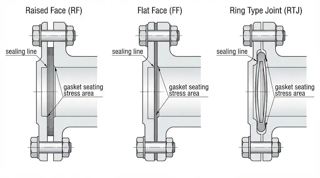
Selection mistakes show up in predictable ways: wrong gasket construction for the flange facing (RF/FF/RTJ), wrong material for the media, and a mismatch between required seating stress and what your bolt or stud size can actually deliver. A useful rule from field work is simple: if you cannot explain how the gasket seals and what load it needs, you are guessing.
- Match facing to gasket type: RF commonly uses spiral wound or kammprofile; RTJ uses ring-type joints; FF often needs full-face coverage and flatness control. If you need a quick refresher on facing choice, Sunhy’s comparison helps: Raised Face vs Flat Face flange.
- Confirm chemical + temperature compatibility: PTFE can cold-flow under load; graphite handles temperature but can accelerate crevice corrosion in chloride service if water is present.
- Verify bolt load capability: seating stress is not “free”—it depends on stud size, grade, lubrication, and the torque-to-tension scatter.
- Check flange-face finish: the gasket you picked may require a specific surface finish window; too smooth can leak, too rough can cut the gasket.
Field example (selection error): A Class 600 RF joint on hot oil leaked after start-up. The gasket was changed from spiral wound to soft sheet to “make sealing easier.” The leak returned within hours because the soft gasket extruded under temperature and bolt load relaxation. Switching back to the correct gasket construction and re-bolting with controlled, staged passes solved it.
Tip: Do not treat gaskets as interchangeable “consumables.” Use a documented selection method, then lock it into your maintenance standard. If you need a step-by-step assembly reference, this Sunhy guide is a good internal baseline: 4 Steps to achieve zero-leakage flange assembly.
Inadequate Bolt Tightening
Improper bolting practices often lead to flange leakage because torque is only an indirect way to achieve bolt tension. Friction at the threads and nut bearing face, lubricant choice, and surface condition all drive torque scatter. A practical way to reduce variation is to use a documented bolting method—such as staged passes, cross-pattern tightening, and controlled lubrication—and follow a recognized guideline such as ASME PCC-1.
If you do not tighten bolts evenly or to the correct target tension, you create localized low gasket stress. That becomes a leak path under pressure or thermal cycling. Also watch for bolt load relaxation after heat-up—temperature and gasket creep/relaxation can unload the joint, especially on the first operating cycle.
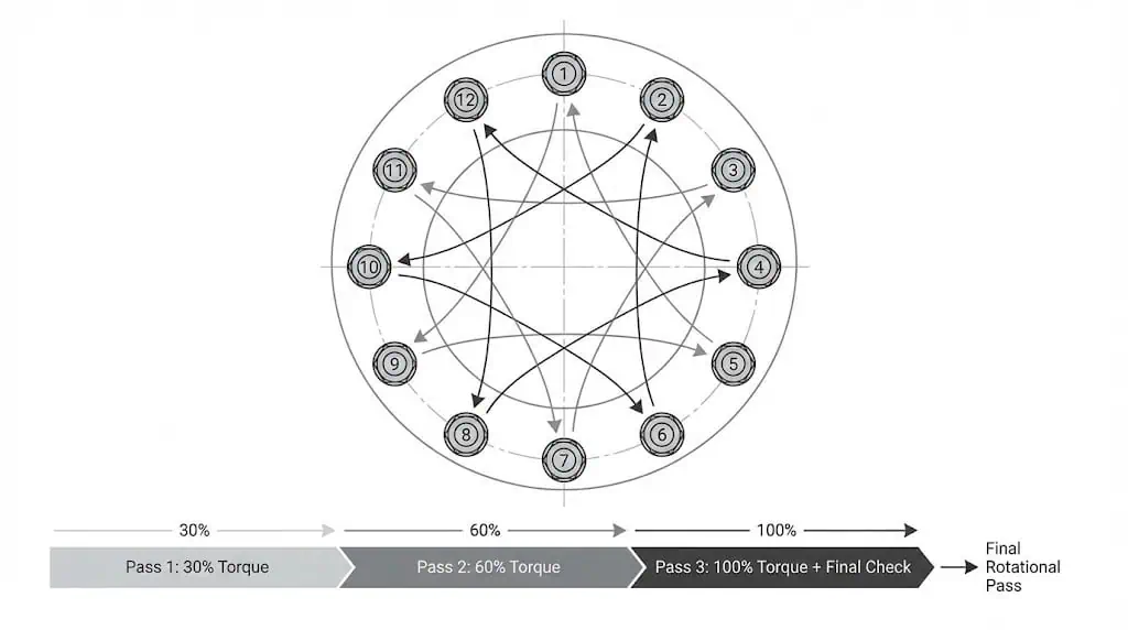
Field example (assembly error): A maintenance team tightened a 12-bolt flange “around the circle.” The joint passed the cold hydrotest but leaked during warm-up. Re-bolting using a cross pattern with staged passes (30% → 60% → 100%) and a final rotational pass stabilized the gasket stress and eliminated the leak.
Flange Surface Damage
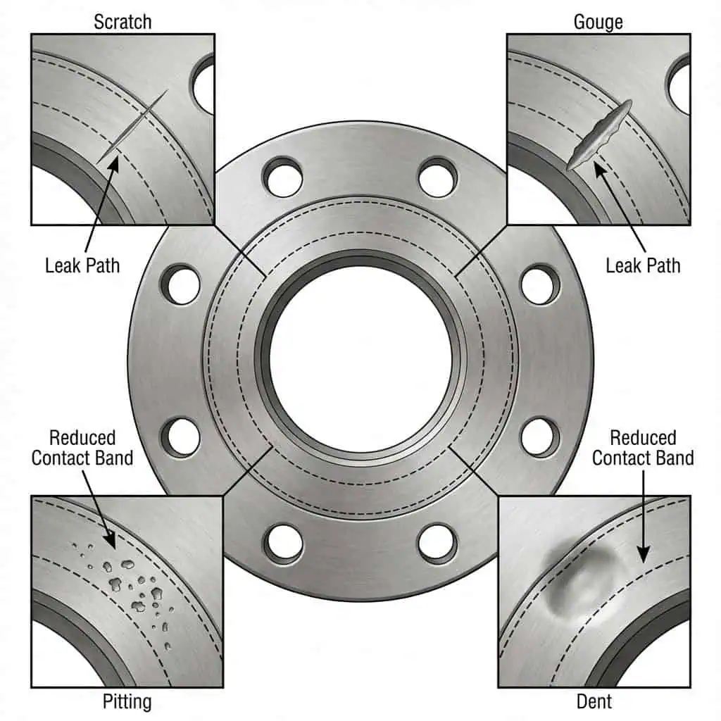
Flange damage is a leading cause of leaks because surface imperfections break the sealing line. Surface finish matters in two directions: deep scratches create a bypass channel, while the wrong overall roughness can reduce gasket bite or cut the gasket.
| Type | Description | Causes |
|---|---|---|
| Scratches | Narrow, elongated marks with sharp bottoms | Created by sharp objects like wire brushes or chisels |
| Gouges | Wide, elongated marks with blunt, rounded bottoms | Caused by dull objects such as screwdrivers or flange jacks |
| Pits | Small, rounded areas of material loss due to corrosion | Often occur in clusters, indicating localized corrosion |
| Dents | Sharp or blunt non-elongated areas caused by impact | Result from equipment collisions during flange positioning |
Even minor radial scratches can compromise the seal in high-pressure service. If you are using spiral wound or kammprofile gaskets, confirm your flange-face finish is in the appropriate window for the gasket type—too rough can damage the gasket; too smooth can reduce frictional bite.
Field example (handling damage): A crew cleaned a raised-face with a steel wire wheel, creating circumferential scratches. The joint “looked clean” but leaked at pressure. Refinishing the face to the correct profile and replacing the gasket corrected the leak without changing flange class or gasket type.
Sunhy’s precision-engineered flanges undergo surface inspections to minimize avoidable defects, but you still need handling discipline on-site—most face damage happens during maintenance, not manufacturing.
Misalignment of Flanges
Misalignment and poor assembly create uneven pressure distribution across the gasket and can also introduce bending into the flange ring. In practice, the worst habit is “pulling flanges together with bolts.” That can permanently distort the flange, damage the gasket, and overload studs.
- Uneven pressure distribution
- Increased stress on piping and joint components
- Reduced efficiency and higher likelihood of leakage under pressure or thermal cycling
- Accelerated wear and fatigue, especially when vibration is present
Misalignment also accelerates gasket scuffing during assembly. If the gasket shifts while you are mating flanges, you can tear the sealing layer before the joint even sees pressure.
Insufficient Piping Flexibility
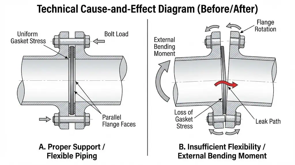
Insufficient piping flexibility shows up as external loads that rotate the flange faces, reduce gasket stress, and open micro-leak paths. Thermal expansion is the common trigger: the system heats up, pipe growth pushes on equipment nozzles, and the flange sees bending moment it was never meant to carry. If you are doing engineering verification for critical service, standards such as EN 1591-1 can help connect external loads, gasket parameters, and leak-tightness expectations.
- Increased stress and loads at flanged joints
- Higher risk of leakage under dynamic or thermal loads
- Need for flexibility and support strategy in piping design
Practical check: if you need a pry bar or come-along to align bolt holes, you likely have an external-load problem. Fix the pipe fit-up and supports first; do not “solve” it with more torque.
Excessive Mechanical Force
Applying too much mechanical force during installation or operation can damage the flange or gasket. In high-pressure systems, the flange joint is sensitive to bending moment, torsion, and axial loads. If those loads cause flange rotation, gasket stress drops and leakage starts—even if your torque values looked correct on the day of assembly.
When you see repeat leaks on the same joint after gasket replacement, treat it as a load-path problem: misalignment, piping loads, or equipment movement is unloading the gasket. Replacing the gasket without addressing the load path usually leads to a second leak.
Improper Support Placement
Improper support placement increases flange leakage risk by creating sustained bending on the joint. The classic field pattern is a heavy valve or instrument spool located near a flange, with the nearest support too far away. That weight turns into a bending moment and slowly works the gasket.
Use supports to remove bending from the flange joint, not just to “hold the pipe up.” If your supports allow the line to sag after startup, your bolt load is competing with gravity and vibration.
Gasket Scuffing and Bolt Load Issues
Gasket scuffing and uneven bolt load are frequent causes of gasket leaks. Scuffing often happens during mating: the gasket drags across the face because the flanges are not parallel or the gasket is not centered. Uneven bolt load then locks that damaged gasket into place.
Use guide studs on large flanges, keep faces parallel during fit-up, and avoid rotating one flange face against the gasket. If you use lubricant, apply it consistently and document it—changing lubrication changes torque-to-tension behavior.
Corrosion and Erosion
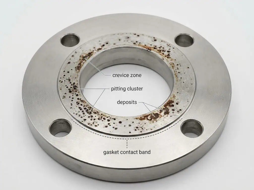
Corrosion is a major threat to flange integrity, especially when moisture and chlorides are present. The most common forms at flange faces are crevice corrosion (under-gasket) and pitting corrosion. Crevice corrosion occurs in small, oxygen-starved gaps between the flange and gasket; pitting appears as small cavities and can cluster. Stainless steels are not corrosion-proof—chloride concentration, temperature, deposits, and stagnant crevices decide the outcome.
- Crevice corrosion: localized, difficult to detect early, often under gaskets and deposits
- Pitting corrosion: small pits that can become leak initiation sites
Field example (under-gasket corrosion): A seawater line developed recurring leaks at the same flange. The gasket was replaced twice with no improvement. After disassembly, crevice corrosion pits were found under the gasket contact band. The fix was to reface the flange, change gasket strategy, and implement wash-down and inspection to prevent salt deposits from sitting in the crevice.
Sunhy’s stainless steel flanges resist corrosion when correctly matched to the service, but corrosion control is a system decision: material grade, deposits, drainage, gasket choice, and inspection all interact.
Vibration and Bolt Fatigue
Vibration can loosen fasteners over time and accelerate bolt fatigue if the joint experiences slip. In vibration environments, thread friction alone is not a reliable locking mechanism. Preventing joint slip is the first priority.
Field example (vibration): A reciprocating machine line leaked intermittently at a flange that “passed” torque checks. The root cause was joint slip under vibration. Improving supports, reducing vibration transmission, and adding a documented locking strategy stabilized bolt load and stopped the leak.
Note: If vibration is part of the duty cycle, treat bolt load retention as a design requirement, not a maintenance afterthought.
Preventing Flange Damage

Correct Gasket Selection
You prevent flange leakage by choosing the right gasket for your system and installing it in a controlled way. Before installation, inspect flange faces for cleanliness, finish, and damage. Never reuse old gaskets, and avoid field improvisation like adding grease unless the gasket procedure explicitly allows it.
Each gasket type—soft sheet, spiral wound, kammprofile, ring-type joint—fits a specific combination of facing, pressure, and temperature. Standardize gasket types and sizes across your operations where possible, but do not standardize beyond what the service can tolerate.
Best Practices for Gasket Selection:
- Match gasket materials and construction to the media, temperature, and pressure, including upset conditions, not just normal operation.
- Confirm facing compatibility (RF/FF/RTJ) and surface finish expectations.
- Use a documented assembly method (for example ASME PCC-1) and keep records for repeatability.
Tip: If your plant sees repeat leaks after “routine gasket replacement,” add a verification step: confirm flange-face finish and parallelism, and confirm bolt-load method. A gasket change alone is often treating the symptom.
Proper Bolt Tightening
Proper bolt tightening ensures a reliable seal and prevents flange damage. Use calibrated tools and follow a cross-pattern sequence. For critical joints, consider tension-control methods where practical, because torque alone can hide large tension scatter.
Bolt Tightening Sequence:
- Lightly tighten the first bolt.
- Move directly across for the second bolt.
- Move 1/4 turn around the circle for the third bolt.
- Move directly across for the fourth bolt.
- Continue this sequence until all bolts are tightened.
Torque Application Steps:
- Start with ~30% of the final target in the first pass (cross-pattern).
- Increase to ~60% in the second pass (same pattern).
- Finish at 100% in the final pass, then perform a final rotational pass to catch relaxation and seating effects.
Note: Even bolt load prevents flange rotation and reduces leakage risk. Keep lubrication consistent—changing lubricant changes torque-to-tension.
Flange Surface Inspection
You must inspect flange surfaces to detect defects that can cause leakage. Non-destructive methods can help you detect corrosion and wall loss without unnecessary disassembly. Techniques such as phased array ultrasonic testing can support screening for corrosion mechanisms that drive under-gasket damage.
| Feature | Description |
|---|---|
| Non-intrusive examination | Inspect without disassembly |
| In-situ and on-stream | Perform inspections while the system operates |
| Cost-effective | Reduce downtime and disassembly costs |
| Corrosion detection | Identify corrosion and measure material loss |
| Safety | Eliminate risks from open flanges |
Tip: Add a face-condition check to your gasket job plan: visual damage, pitting band under the gasket, and a quick surface-finish confirmation. Many repeat leaks are repeatable because nobody checks the face condition before reassembly.
Accurate Flange Alignment
Accurate alignment prevents types of flange damage and supports stable gasket stress. Use alignment pins or flange alignment tools to position flanges correctly. Clean all surfaces and check that pipe ends are straight and square. After installation, inspect welds and conduct a pressure test to confirm no leakage.
Alignment Steps:
- Clean flanges and pipes.
- Use alignment tools for precise fit.
- Mark flanges for correct alignment.
- Measure distances for consistency.
- Adjust with shims or spacers as needed.
Callout: If you need to “force” alignment with studs, stop and correct the piping or support condition first. Bolts are not alignment tools.
Flexible Piping Design
Flexible piping design reduces stress on flanged joints and prevents flange leakage. Use the flange standard that matches your design basis (for example ASME B16.5) and follow an assembly guideline (for example ASME PCC-1). When external loads are significant, consider calculation and verification approaches such as EN 1591-1.
| Design Standard | Description |
|---|---|
| ASME B16.5 | Flange dimensional and pressure-temperature basis for many piping systems |
| ASME PCC-1 | Assembly guidance for maintaining joint integrity and gasket stress |
- Flexible piping accommodates thermal expansion and movement.
- Proper design reduces flange rotation and helps maintain seal integrity.
Controlled Mechanical Force
Control mechanical force during installation to avoid flange damage. Tighten bolts in a cross-pattern for uniform stress. Rather than chasing maximum torque, target a bolt stress range that achieves required gasket stress without yielding studs or rotating the flange. In practice, the target depends on stud grade, lubrication condition, gasket type, and joint geometry.
Mechanical Force Control Steps:
- Initial Pass: Tighten bolts to ~30% of final target in a cross-pattern.
- Second Pass: Increase to ~60% in the same pattern.
- Final Pass: Tighten to 100% in the same sequence, then do a rotational pass to detect relaxation.
Tip: Avoid over-tightening. You can crush gaskets, rotate flanges, and still leak—because you created uneven gasket stress, not more sealing.
Strategic Support Placement
Strategic support placement prevents flange damage by maintaining alignment and reducing sustained bending. Choose support spacing based on pipe diameter, material, and fluid density. Use rigid, spring, or sliding supports as needed, and define anchor points where movement must be controlled.
| Support Consideration | Description |
|---|---|
| Support Spacing | Determined by pipe diameter, material, and fluid density |
| Support Type | Rigid, spring, or sliding supports for different requirements |
| Anchor Points | Fixed points to prevent movement in all directions |
- Regular inspections by qualified personnel maintain system integrity.
- Include supports, restraints, and flange joints in the same inspection plan.
Managing Gasket Load
You ensure a reliable seal by managing gasket load correctly. Tighten bolts with a method that controls bolt tension, not just torque. Use multiple passes and keep flanges parallel. If your procedure includes re-torque after thermal cycling, follow the gasket manufacturer’s guidance—some gasket types and services do not allow hot re-torque without additional safety controls.
Gasket Load Management Steps:
- Ensure flanges are parallel before tightening.
- Use a documented cross pattern and staged passes.
- Control lubrication consistently and record it as part of the job plan.
Corrosion Prevention
Corrosion and crevice attack threaten flange integrity. Choose materials and maintenance methods based on the actual corrosion mechanism. Stainless steel performance in chlorides is driven by temperature, deposits, and crevices; 316 is not a guarantee. If your system is coastal, offshore, or uses seawater or brine, add deposit control and under-gasket inspection to your routine.
| Type of Coating | Benefits |
|---|---|
| Epoxy Coatings | Excellent adhesion, durability, and chemical resistance |
| Polyurethane Coatings | Flexible, durable, high resistance to abrasion and UV |
| Zinc-Rich Primers | Provides cathodic protection, effective in marine environments |
- Schedule inspections and use non-destructive methods to detect hidden corrosion.
- Control deposits, drainage, and stagnant crevices around the flange and gasket interface.
- Consider higher alloy grades where chloride stress is high and justified by risk.
Callout: If you see recurring leaks with visible pitting under the gasket band, stop gasket swapping. Reface or replace the flange face and fix the corrosion driver—chlorides, deposits, or stagnant crevice.
Vibration Control
Vibration control prevents bolt fatigue and flange leakage by preventing joint slip and preload loss. Use a support strategy that reduces vibration transmission, and apply a locking method that matches the risk.
Vibration Control Techniques:
- Improve supports and restraints to reduce vibration at the flange joint.
- Use locking methods appropriate to the service and criticality; do not rely on extra torque.
- Install flexible connectors where they reduce transmitted vibration without creating new load paths.
- Include bolt-load checks and leak monitoring in your maintenance plan for vibrating equipment.
Tip: Treat vibration as a root cause. If the joint slips, the bolts can loosen even when the original torque values were correct.
By following these strategies to prevent flange damage, you reduce the risk of leakage, failure, and costly downtime. Precision-engineered products help, but the leak-free outcome is built by joint design + correct gasket + correct bolt load + controlled external loads.
Common Flange Leaks and Solutions
Identifying Flange Leaks
You can spot flange leaks early by combining basic checks with the right diagnostic tools. A reliable approach is a step-by-step method: visual checks first, then targeted testing.
- Visual Inspection: Look for moisture, corrosion, deposits, or wash marks around the flange.
- Pressure Testing: Use hydrostatic or pneumatic methods consistent with your plant procedure.
- Ultrasonic Testing: Detect escaping gas and support thickness screening near the joint.
- Acoustic Monitoring: Continuous sensors for early warning in critical service.
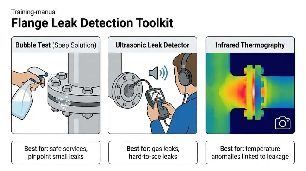
- Infrared Thermography: Temperature anomalies can indicate leakage pathways.
| Diagnostic Tool/Method | Description |
|---|---|
| Bubble Test | Apply soap solution and watch for bubbles at the flange connection. |
| Ultrasonic Leak Detectors | Detect high-frequency sounds from escaping fluids. |
| Pressure Test | Seal the flange and monitor for pressure drops. |
| Leak Detection Sprays | Change color when exposed to leaking fluid. |
| Visual Flange Gap Analysis | Check for irregular gaps that may indicate rotation or misalignment. |
| Acoustic Emission Testing | Listen for high-frequency sounds from stressed materials. |
| Infrared Thermography | Spot heat patterns linked to fluid leaks. |
Tip: If a flange leak appears after warm-up but not at cold hydrotest, suspect bolt-load relaxation, flange rotation from external load, or gasket creep—not just bad torque.
Quick Response Strategies
Responding quickly to flange leaks reduces escalation and secondary damage. Train your team to recognize leak signatures and apply a controlled response plan based on hazard and media.
- Use flange shields where justified to reduce spray risk in hazardous service as part of a broader safety strategy.
- Do not torque harder as a default response—verify alignment and load path first.
- Escalate to shutdown or repair when the media or leak rate exceeds your safety envelope.
- Use inspection planning aligned with your plant’s code program; many facilities base piping inspection management on standards such as API 570.
Field example (repeat leak): A joint leaked three times in six months despite gasket replacement. The real issue was piping load from a nearby unsupported spool that slowly rotated the flange under thermal cycling. Correcting supports and re-bolting per a controlled sequence stopped the recurrence.
By using these solutions, you can prevent leaks, reduce corrosion-driven flange damage, and avoid pressure-related failures in your system.
You can prevent flange leakage by staying proactive with maintenance and inspections. In many plants, the biggest gains come from standardizing gasket selection, training bolt-up discipline, and controlling external loads. For deeper internal reading on leakage mitigation, Sunhy also covers a related case here: flange leakage in high-pressure hydrogen service solutions.
| Standard | Application Area |
|---|---|
| ISO 6164 | Hydraulic high-pressure systems |
| ANSI/ASME | Pipeline flanges in the US |
| API | Oilfield high-pressure applications |
| DIN | European and maritime industries |
Stay vigilant and use these preventive measures to keep your systems leak-free.
FAQ
What is the most common cause of flange leakage?
In practice, the most common root pattern is low or uneven gasket stress.
This happens when gasket selection is mismatched, bolt load is uneven, flange faces are damaged, or external piping loads rotate the joint. If you fix only one factor, for example a new gasket, the leak often returns unless bolt load and load path are corrected.
How can you quickly detect a flange leak?
You can use a bubble test for safe services or ultrasonic leak detection for gas leaks.
- Apply a soap solution and look for bubbles where safe and permitted.
- Use an ultrasonic device to detect escaping gas and locate the source.
What should you do if you find a leaking flange?
Follow your plant safety procedure first, then diagnose the root cause.
- Assess hazard (media, pressure, temperature) and decide whether shutdown is required.
- Do not default to more torque. Check alignment, supports, and evidence of flange rotation.
- Replace the gasket only after verifying flange-face condition and bolt-up method.
How often should you inspect high-pressure flanges?
Use a risk-based interval, not a fixed calendar number.
High-pressure flanges should be checked during commissioning, after the first thermal cycle when practical, and then aligned with your plant inspection program, often managed under standards such as API 570. Increase frequency where vibration, thermal cycling, chlorides, or repeated maintenance history exists.
- Include visual checks during rounds where feasible.
- Use targeted NDE where corrosion mechanisms are credible.
Can you reuse gaskets when repairing a flange?
No. You should not reuse gaskets.
Once compressed, a gasket’s recovery and sealing characteristics change. Reuse increases the chance of leakage, especially in high-pressure or thermal cycling service.


