
ASME B16.5 is the primary dimensional and rating standard for common pipe flanges and flanged fittings in many U.S.-influenced projects. If you have ever seen drawings labeled “ANSI flanges,” this is usually the family they mean. In engineering terms, B16.5 exists so that bolting patterns, facing details, and pressure-temperature ratings stay interchangeable across manufacturers within the standard’s scope.
It is used heavily in oil and gas, chemical processing, power generation, water treatment, and general industrial utility piping. What matters in practice is that B16.5 gives you a controlled “interface” (NPS, class, face type, drilling, tolerances, and marking rules) so you can avoid field rework caused by bolt-hole mismatch, wrong gasket seating width, or incompatible facing selections.
| Benefit | Description |
|---|---|
| Pressure–Temperature Ratings | Defines Class ratings (150–2500) and the allowable pressure at temperature by material group; class is a designation, not a direct PSI value. |
| Ease of Installation | Standardized bolt circle diameter (BCD), hole count, and facing geometry reduce alignment issues and shorten fit-up time. |
| Traceability & Interchangeability | Requires permanent marking (size, class, material, manufacturer/heat ID) to support QA/QC, MTR review, and maintenance traceability. |
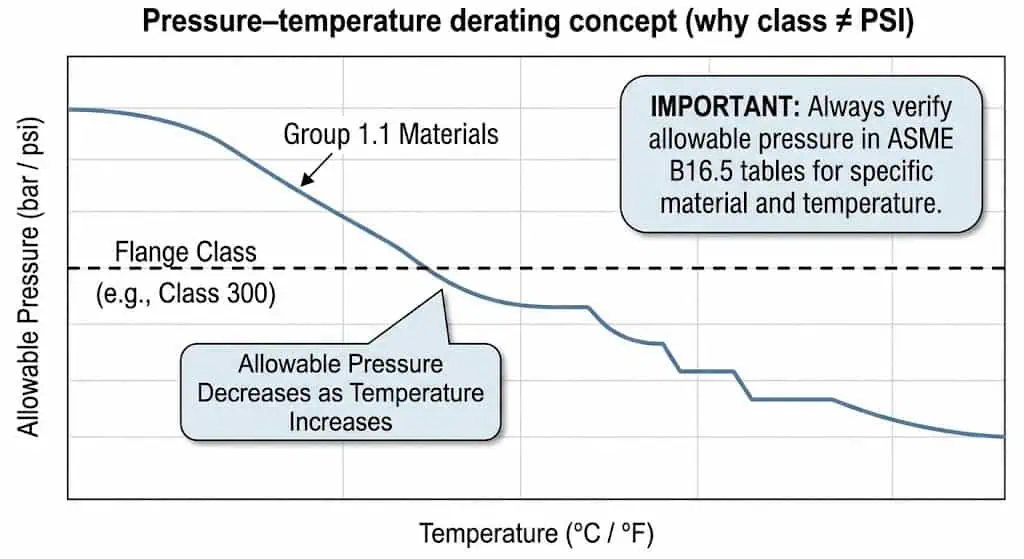
Field note (common misunderstanding): A “Class 150” flange is not “150 psi.” The safe working pressure depends on temperature and the selected material group in the rating tables. If you spec solely from ambient numbers and ignore temperature derating, you can end up with a joint that passes hydro at ambient but seeps under hot service.
Sunhy’s stainless steel flange products are manufactured to the relevant ASME requirements (dimensions, drilling, facing, and marking) so you can maintain compatibility during procurement and replacement work.
ASME B16.5 Scope & Limitations
Covered Flanges & Flanged Fittings
ASME B16.5 covers a defined set of metallic pipe flanges and flanged fittings used in industrial piping systems.
Within scope, you can treat B16.5 as the “common language” for: nominal size (NPS), pressure class, facing type (for gasket compatibility), drilling (bolt pattern), and the dimensional tolerances needed for predictable assembly. Typical flange types covered include:
- Weld Neck (WN) Flanges: Used where fatigue, bending, or higher cyclic duty makes hub geometry valuable.
- Slip-On (SO) Flanges: Often selected for utility lines where fit-up speed and cost control matter.
- Blind (BL) Flanges: Used for isolation, hydrotest blinds, and future tie-in points.
- Socket Weld (SW) Flanges: Common on small-bore services; installation quality is sensitive to proper socket gap and weld profile.
- Threaded (TH) Flanges: Used where welding is restricted; not suitable for severe vibration or high thermal cycling without additional controls.
- Lap Joint (LJ) Flanges: Used with a stub end for frequent dismantling or where a rotating flange helps bolt alignment.

Engineering example #1 (interchangeability failure): A maintenance team replaced an EN1092-1 PN flange with an “equivalent” ASME flange by rough pressure class comparison. Bolt holes did not line up in the field because PN drilling and ASME drilling are not interchangeable. The job lost a shift to rework. The preventer is simple: confirm the governing standard on the isometric (ASME vs EN/DIN), then match drilling and facing—not only pressure.
Practical scope check (fast):
- Confirm the project standard: ASME (B16.5/B16.47) vs EN1092-1 (PN/DN) before ordering.
- Confirm NPS range is within B16.5; for large diameter, you may need ASME B16.47.
- Confirm facing type matches the mating flange and gasket design (RF/FF/RTJ, etc.).
Sunhy manufactures stainless steel flanges to the correct dimensional and marking requirements so replacements remain compatible during shutdown work.
Size Range & Exclusions
ASME B16.5 (current editions) applies primarily to pipe flanges and flanged fittings from NPS 1/2 inch through 24 inches, with Class ratings 150 through 2500 within defined size limits.
This size range covers most piping needs in industrial settings, and the standard provides rating tables by material group. In practice, you should also pay attention to class-by-size boundaries (for example, Class 2500 is not available across every size in the same way as lower classes). If your spec sits near the edge (large diameter, high class, or elevated temperature), confirm the specific NPS/Class combination against the current B16.5 tables.
- The ASME B16.5 standard specifies common metallic flanges and flanged fittings.
- The most used nominal size range is NPS 1/2 through NPS 24.
- It defines pressure classes 150, 300, 400, 600, 900, 1500, and 2500 with size availability defined by the standard.
However, ASME B16.5 does not cover every flange type or size. For larger diameter steel flanges, you typically reference ASME B16.47, which is designed for large diameter applications.
Important clarification on the table below: The “Type 05/11/12/13/21” numbering is commonly seen in EN1092-1/DIN documentation (metric PN/DN world), not in ASME B16.5 nomenclature. It is shown here as a cross-reference because many EPC packages mix EN and ASME documents. If your project is governed by ASME B16.5, do not use EN flange type numbers for ordering.
| Flange Type | Nominal Size Limitations |
|---|---|
| 05 | Up to DN 600 |
| 11 | Up to DN 600 |
| 12 | Up to DN 600 |
| 13 | Up to DN 600 |
| 21 | Up to DN 600 |
| Other Types | To be agreed upon |
")
Engineering example #2 (wrong standard on large diameter): A project ordered “B16.5” flanges for a large diameter cooling water header. When the spools arrived, the bolt circle did not match the mating equipment nozzles built to a large diameter standard. The fix required re-drilling or replacement. The preventer: for NPS above the B16.5 scope, align early to B16.47 (Series A/B) or the project’s metric PN standard.
Sunhy’s stainless steel flanges are manufactured to the correct specification for standard and custom requirements, reducing compatibility risk during installation.
Tip: Before ordering, lock three items in writing: (1) governing standard (ASME vs EN/DIN), (2) NPS/DN and class/PN, and (3) facing type (RF/FF/RTJ). Most field-fit failures trace back to one of these three being assumed.
B16.5 Pressure Ratings & Materials
Pressure Classes Explained
What are the seven pressure classes defined by ASME B16.5?
ASME B16.5 defines seven pressure classes for pipe flanges and flanged fittings: Class 150, 300, 400, 600, 900, 1500, and 2500. These classes organize standardized dimensions and rating tables. In practical engineering work, you interpret the class using the pressure-temperature tables for the selected material group and temperature range (class alone is not enough).
| Class | Design Pressure Range | Key Features & Applications |
|---|---|---|
| Class 150 | Example reference at 100°F: ~285 psi (1.96 MPa)* | Common in utility service: water, air, low-pressure steam. Confirm derating for hot service and confirm gasket selection for low bolt loads. |
| Class 300 | Example reference at 100°F: ~740 psi (5.10 MPa)* | Moderate pressure services: process lines, oil/gas utilities. Watch temperature derating and bolt-up practice to prevent hot seepage. |
| Class 400 | Example reference at 100°F: ~990 psi (6.83 MPa)* | Less common; used where class steps align to equipment ratings or legacy piping classes. |
| Class 600 | Example reference at 100°F: ~1,480 psi (10.20 MPa)* | Higher pressure services and critical utilities; gasket stress and bolt preload control become more sensitive. |
| Class 900 | Example reference at 100°F: ~2,220 psi (15.30 MPa)* | High-pressure systems; verify flange facing, gasket type, and bolting grades; QA/QC on facing finish matters. |
| Class 1500 | Example reference at 100°F: ~3,705 psi (25.55 MPa)* | Very high pressure; typically paired with thick-wall piping and controlled assembly practices. |
| Class 2500 | Example reference at 100°F: ~6,175 psi (42.58 MPa)* | Extreme high pressure; size availability is limited and joint integrity depends heavily on procedure and inspection. |
*Typical reference values at 100°F are widely used as a quick orientation only. Always verify the allowable pressure at the actual operating temperature and the specific material group using the current ASME B16.5 rating tables.
")
How do you interpret pressure ratings for practical use?
Start with the real operating conditions: design pressure, design temperature, fluid phase (gas/liquid), cycling, and upset scenarios. Then select material group and class from the B16.5 pressure-temperature tables. If the service is hot, do not assume ambient ratings apply—most materials derate as temperature rises. For bolted joints that must stay tight under cycling, assembly quality and gasket stress control can matter as much as the nominal class.
| ASME B16.5 Flange Classes | Maximum Pressure (at 100°F) |
|---|---|
| Class 150 | 285 psi |
| Class 300 | 740 psi |
| Class 400 | 990 psi |
| Class 600 | 1,480 psi |
| Class 900 | 2,220 psi |
| Class 1500 | 3,705 psi |
| Class 2500 | 6,175 psi |
Tip: If the joint is safety-critical or leak-intolerant, add an assembly standard (torque/turn-of-nut control, lubrication control, gasket handling, flange facing checks). Many organizations reference ASME PCC-1 for bolted flange joint assembly guidance.
Engineering example #3 (hot seepage after start-up): A Class 300 joint on hot steam service was selected using “typical” ambient ratings, and bolts were tightened without lubricant control or a defined sequence. The joint passed a cold hydro but began to weep after thermal expansion and gasket relaxation. The fix was not “a higher class” by default—the fix was correct rating verification at temperature, correct gasket selection, and controlled assembly (sequence, lubrication, re-tightening plan where allowed by procedure).
Where are different pressure classes used?
- Class 150: General utility piping, water lines, low-pressure steam, non-critical services.
- Class 300: Moderate pressure process piping, industrial utilities, many refinery service lines (subject to temperature derating).
- Class 600: Higher pressure steam and process services, gas compression auxiliaries, refinery high-pressure utilities.
- Class 900 and above: High-pressure and critical services, power generation high-energy systems, offshore/high-pressure gas and injection systems.
")
Material Requirements for Flanges
What materials does ASME B16.5 specify for flanges and flanged fittings?
ASME B16.5 organizes materials into groups and assigns rating tables by material group. In procurement, you normally specify the flange material by ASTM/ASME material designation (for example, forged carbon steel, forged stainless steel, forged alloy steel, or nickel alloys) and then verify the applicable rating table for that material group.
| Material Type | ASTM Standard | Chemical Properties | Mechanical Properties |
|---|---|---|---|
| Carbon Steel | ASTM A105/A105M | General forged carbon steel for piping components; chemistry limits depend on grade and heat. | Mechanical requirements are defined in the ASTM standard and verified by MTR/testing. |
| ASTM A350 LF2 | Low-temperature service carbon steel forging; impact requirements apply where specified. | Selected for low-temperature toughness requirements. | |
| Stainless Steel | ASTM A182 (e.g., F304/F316) | Corrosion-resistant alloy family; grade choice depends on chloride exposure, temperature, and corrosion mechanism. | Mechanical requirements defined by the ASTM specification and verified by certification/testing. |
| Alloy Steel | ASTM A182 (e.g., F11/F22) | Cr-Mo alloy steels for elevated temperature service; chemistry supports creep strength in design codes. | Used where high-temperature strength is required; verify PWHT and code compliance. |
| Nickel-based Alloy | ASTM B564 (e.g., N06625) | Used in severe corrosion or high-temperature environments where stainless steels are insufficient. | Specified for demanding corrosion/temperature duty; certification is critical. |
| Material Group | Nominal Designation | Common Applications |
|---|---|---|
| Carbon Steel | A105, A350 Gr. LF2 | General piping systems, utilities, many hydrocarbon services (with corrosion allowance and coating as required). |
| Alloy Steel | A182 Gr. F1, F11, F22 | High-temperature applications (refinery/process heaters, steam lines), where strength at temperature matters. |
| Stainless Steel | A182 Gr. F304, F316 | Corrosive environments; grade selection depends on chloride level, temperature, and pitting/SCC risk. |
| Duplex Stainless Steel | A182 Gr. F51 | Higher strength and improved chloride resistance; used in seawater and aggressive chloride services. |
How do you ensure material quality and compliance with ASME B16.5?
Do not rely on “stainless” as a one-word spec. Verify: material designation, heat number, MTR, dimensional inspection, and any required NDE. For critical services, confirm that marking on the flange matches paperwork (heat/lot traceability). If your project uses a bolted-joint assembly standard, align bolting grade, gasket type, and facing finish with that procedure.
| Testing Process | Description |
|---|---|
| Dimensional Inspection | Confirms OD/ID, BCD, thickness, facing dimensions, and drilling match the selected standard (B16.5/B16.47/EN1092-1). |
| Visual Examination | Checks facing damage, dents, corrosion, and machining defects that can create leak paths. |
| Positive Material Identification (PMI) | Used when material mix-up risk is high (especially stainless vs duplex vs nickel alloys). |
| Ultrasonic Testing (UT) | Detects internal discontinuities in forgings when specified by project QC. |
| Magnetic Particle (MT) / Dye Penetrant (PT) | Identifies surface-breaking flaws (method depends on material and specification). |
| Third-party Inspections | Independent verification of compliance and traceability on critical packages. |
Note: Material grade alone does not guarantee leak-tight performance. In real installations, most chronic leaks trace to facing damage, gasket selection errors, bolt preload scatter, or mixed standards (ASME vs EN). Control those variables early.
Summary:
You select pipe flanges and flanged fittings by matching the correct governing standard, pressure class at temperature (rating tables), and the correct material designation with traceability. Sunhy’s stainless steel flanges support demanding industrial environments with dimensional control and compliant marking.
Dimensions, Tolerances & Marking
Standard Dimensions for Flanges
What are the standard dimensions for pipe flanges according to ASME B16.5?
B16.5 standardizes the key interface dimensions that determine whether a joint will assemble without forcing: OD/ID envelope, bolt circle diameter (BCD), hole count and diameter, thickness, hub geometry (where applicable), and facing geometry. In the field, these are the dimensions that decide if you can bolt up without slotting holes or fighting alignment.
| Dimension Type | Description |
|---|---|
| Nominal Pipe Size (NPS) | Defines the nominal size family used for dimensional selection and compatibility. |
| Pressure Classes | Class affects thickness, drilling, and facing details (and must be verified at temperature via rating tables). |
| Face Types | Face type drives gasket compatibility (RF/FF/RTJ and other facing designs where applicable). |
| Bolt Circle Diameter (BCD) | Critical for bolt alignment; mismatch is a common root cause of field-fit failures across standards. |
| Number and Size of Bolt Holes | Controls bolt selection and load distribution; hole diameter and spacing affect assembly tolerance. |
Installation checklist (fast, before bolt-up):
- Confirm flange faces are clean, undamaged, and free of deep radial scoring.
- Confirm gasket OD/ID matches the facing seating area (not overhanging into bore unless designed).
- Confirm bolts/nuts/washers match the procedure (grade, length, lubrication plan).
- Dry-fit two bolts across the BCD before lifting heavy spools into final position (catches drilling mismatch early).
What are the tolerance requirements for flange dimensions?
Dimensional tolerances exist so that real parts from different manufacturers still assemble. While tolerance values depend on dimension and size range, the practical point is: do not assume “close enough” on bolt circle or face geometry. Tolerance stack-up is where intermittent leaks are born.
| Dimension | Tolerance Requirements |
|---|---|
| Outside Diameter (O.D.) | ±1/16″ (1.6mm) for 24″ or less; ±1/8″ (3.2mm) for over 24″ |
| Inside Diameter (I.D.) | ±1/32″ (0.8mm) for 10″ and smaller; +1/8″ (3.2mm) for 12″ to 18″; -1/16″ (1.6mm) for 20″ and larger |
| Diameter of Contact Face | ±1/32″ (0.8mm) for 1/16″ raised face; ±1/64″ (0.4mm) for 1/4″ raised face, tongue & groove |
| Diameter of Hub at Base | ±1/16″ (1.6mm) for 24″ or smaller; ±1/8″ (3.2mm) for over 24″ |
| Diameter of Hub at Welding | +3/32″ (2.4mm), -1/32″ (0.8mm) for 5″ and smaller; +5/32″ (4.0mm), -1/32″ (0.8mm) for 6″ and larger |
| Drilling | ±1/16″ (1.6mm) for bolt circle; ±1/32″ (0.8mm) for bolt hole spacing |
| Thickness | ±1/8″ (3.2mm) for 18″ and smaller; ±3/16″ (4.8mm) for 20″ and larger |
| Length of Hub | ±1/16″ (1.6mm) for 10″ and smaller; ±1/8″ (3.2mm) for 12″ and larger |
Sunhy’s QA team inspects dimensional criticals so the flange assembles predictably without forced alignment and without uneven gasket loading.
Tip: If you see bolt-hole “almost aligns,” stop and verify standard (ASME vs EN), class/PN, and BCD before you torque. Forcing bolts through misaligned holes can damage gasket seating and create a leak path that only shows up after thermal cycling.
Marking & Identification
What marking and identification requirements does ASME B16.5 mandate for flanges and flanged fittings?
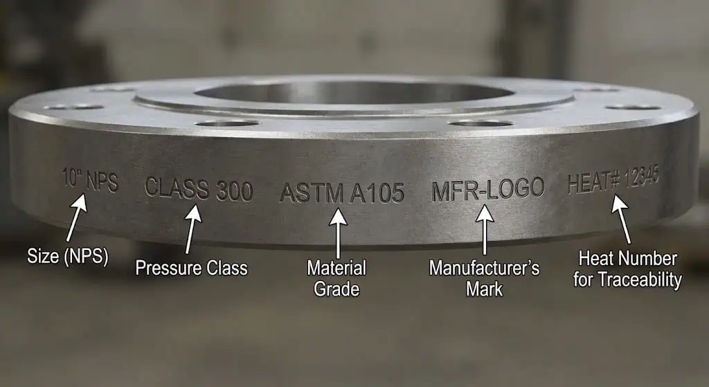
Marking is not a formality. In shutdown work, marking is often the only fast way to confirm you are installing the intended size/class/material—especially when parts are mixed in staging yards. If the flange is unmarked or markings do not match paperwork, treat it as a QC hold until traceability is restored.
- ASTM/ASME material specification and grade symbol
- Heat (melt) number or traceable batch/lot identifier
- Pressure rating class (e.g., 150, 300)
- Standard designation (B16.5 / B16)
- NPS size marking
- For RTJ flanges: ring groove designation (where applicable)
What are best practices for marking and identification?
Use marking as part of a short receiving inspection that prevents the most expensive mistake: installing the wrong material in a corrosive or high-temperature service.
- Manufacturer identification or logo
- Material grade that matches the MTR (do not accept “stainless” as a substitute)
- Facing type identification where used in your QC system (RF/RTJ, etc.)
- Batch number and heat number tie-back to certification
- Project-required compliance markings (if specified by client spec)
Engineering example #4 (material mix-up): A spool in chloride-bearing service was assembled with one flange from the wrong stainless grade due to mixed pallets and unreadable markings. It looked fine at commissioning but later showed pitting at the flange/gasket edge. The preventer: readable permanent marking + PMI spot checks on critical services + receiving inspection that reconciles markings with MTRs.
Sunhy engraves required information for traceability, material confirmation, and lifecycle maintenance control.
Comparing ASME B16.5 to Other Standards
Differences from Other Flange Standards

Key Difference:
ASME B16.5 is a class/NPS system within its size range, while other standards address larger sizes or use metric PN/DN rating systems.
ASME B16.47 is commonly used for large diameter steel flanges (Series A and Series B). EN1092-1/DIN standards use DN sizing and PN ratings and often different drilling patterns and facing conventions. You cannot “convert” reliably by pressure alone; you must match drilling and facing to avoid fit-up failures.
| Flange Type | ASME B16.5 | ASME B16.47 Series A | ASME B16.47 Series B |
|---|---|---|---|
| Nominal Pipe Size | <NPS 26 (typical scope NPS 1/2–24) | ≥NPS 26 | ≥NPS 26 |
| Weld Neck Flange | Class 150–2500 (within size limits) | Class 150–900 | Class 75–900 |
| Blind Flange | Class 150–2500 (within size limits) | Class 300–900 | Class 300–900 |
| Slip On Flange | Class 150–1500 (within size limits) | – | – |
| Lap Joint Flange | Class 150–2500 (within size limits) | – | – |
| Socket Weld Flange | Class 150–1500 (within size limits) | – | – |
| Threaded Flange | Class 150–2500 (within size limits) | – | – |
| Ring Joint Face | Class 150–2500 (within size limits) | Class 300–900 | Class 300–900 |

You will also see that DIN and EN1092-1 standards use PN ratings and DN sizes, while B16.5 uses ANSI class ratings and NPS sizes. The table below shows how dimensional and rating conventions differ:
| Standard | Dimensional Characteristics | Pressure Rating Characteristics |
|---|---|---|
| ASME B16.5 | Class/NPS system with defined drilling/facing/tolerances within scope | Rated by pressure-temperature tables per material group (class designation) |
| DIN | Metric system with DN/PN; drilling and facing conventions differ | Rated by PN class and temperature conventions per standard |
| EN 1092-1 | Similar metric DN/PN framework; multiple flange “types” in EN naming | PN ratings; not directly interchangeable with ASME class without drilling/facing checks |
Tip: If you have mixed equipment (some nozzles built to EN, others to ASME), plan transition spools or adapter strategies early. Do not assume gasket “will take up the mismatch” when drilling and facing are different.
Updates & Revisions
Major Updates:
Across its revisions, ASME B16.5 has updated terminology and incorporated changes that impact dimensions, rating presentation, and standard alignment. In real procurement work, the critical rule is: confirm the edition specified by the project and avoid mixing editions without review.
| Major Updates and Revisions | Description |
|---|---|
| Integrated U.S. Customary units | Incorporated into the main text |
| Revised flange thickness nomenclature | Updated terminology |
| Added straight hub welding flanges | New flange types introduced |
| Deleted Appendix II | Appendix II removed |
| Adjustments to sealing surface heights | Modified specifications |
| Minimum flange thickness designations | Changed minimum thickness requirements |
You will also find that the B16 standards family is maintained actively by ASME. For any project with strict compliance requirements, use the project-specified edition and verify that your purchase order, inspection plan, and markings align with that edition.
- Confirm scope (size/class limits) before ordering high-class or unusual sizes.
- Confirm alignment to large diameter standard where applicable (B16.47 for large sizes).
- Confirm bolt-up procedure requirements for leak-intolerant services (often PCC-1 is referenced).
Note: Compliance is not only about buying the right standard flange. Field leaks are often installation-driven. If the service is critical, define gasket type, bolting grade, lubrication, tightening sequence, and inspection checks as part of the spec.
ASME B16.5 supports safe, maintainable piping systems when applied correctly.
You gain predictable fit-up, controlled interchangeability, and traceability by following the standard and verifying the correct rating at operating temperature.
| Benefit | Description |
|---|---|
| Assured Quality | Standardized interface dimensions and required marking improve procurement and maintenance control. |
| Enhanced Safety | Correct rating selection at temperature reduces risk of bolted joint failure and leaks. |
| Global Compatibility Planning | Clear separation between ASME and EN systems helps avoid drilling/facing mismatches. |
| Cost-Effectiveness | Less field rework, fewer mismatch-related delays, and improved lifecycle traceability. |
Choose flanges that meet ASME B16.5, such as Sunhy’s stainless steel flanges, for dependable performance.
You should always confirm the governing standard, class at temperature, facing type, and material traceability before installation.
FAQ
What does ASME B16.5 cover?
ASME B16.5 covers common metallic pipe flanges and flanged fittings, typically in the NPS 1/2″ to 24″ range.
It defines interface dimensions (drilling, facing, thickness), pressure class conventions, and pressure–temperature ratings by material group, plus tolerances and marking rules. For larger diameter steel flanges, you usually reference ASME B16.47.
How do you identify a compliant flange?
Check for permanent markings and verify them against paperwork.
At minimum, look for:
- Manufacturer’s logo/name
- Material grade/specification (ASTM/ASME designation)
- Pressure class
- B16.5 (or B16) designation
- NPS size
- Heat/lot number traceable to the MTR
If markings are missing or inconsistent, treat it as a QC hold until traceability is restored.
Why is pressure class important?
Pressure class is the starting point for safe ratings—but you must apply it at temperature and by material group.
You match pressure class and material group to your operating temperature using the ASME pressure–temperature rating tables. This prevents the common failure mode of selecting a flange that looks acceptable at ambient but derates below your required pressure at operating temperature.
| Class | Max Pressure (100°F) |
|---|---|
| 150 | 285 psi |
| 300 | 740 psi |
| 600 | 1,480 psi |
What materials are commonly used for ASME B16.5 flanges?
Common materials include carbon steel, alloy steel, and stainless steel—selected by duty, corrosion mechanism, and temperature.
Carbon steel (e.g., ASTM A105) is common for general service. Alloy steels (e.g., Cr-Mo grades) are used for elevated temperature. Stainless steels (e.g., ASTM A182 F304/F316) are used for corrosion resistance, but grade selection must consider chloride exposure, temperature, and pitting/SCC risk.
Can Sunhy manufacture flanges to other standards?
Yes. Sunhy can manufacture flanges to ASME, DIN, and EN1092-1 standards based on your project requirements.
For mixed-standard projects, confirm drilling and facing early and specify the governing standard on drawings and purchase orders to avoid field-fit issues.


