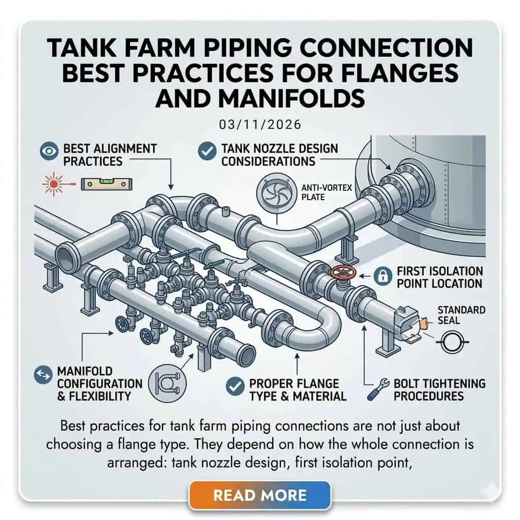
Best practices for tank farm piping connections are not just about choosing a flange type. They depend on how the whole connection is arranged: tank nozzle design, first isolation point, flange location, manifold layout, drainage, support, thermal movement, settlement tolerance, spill control, and maintenance access. In tank farms, many repeated leakage and maintenance problems come from connection geometry and operating practice, not from flange material alone.
That is why tank farm piping should be reviewed as a connection system rather than as separate parts. A flange that is technically correct on a datasheet can still become a chronic leak point if the nozzle sees pipe strain, if the manifold traps product, or if the first break point is placed where maintenance access is poor. The practical goal is simple: keep the connection safe, easy to isolate, easy to drain, easy to maintain, and hard to misoperate. For flammable-liquid tanks, OSHA 1910.106 requires pipe connections below the allowable liquid level to have valves or cocks located as closely as practicable to the tank shell. That is one reason the first isolation point is such a critical design decision.
Field rule: In tank farms, the first flange, the first valve, the manifold branch, and the low-point drain usually matter more than the long straight run.
| Connection Area | Why It Matters |
|---|---|
| Tank nozzle to first flange | High-consequence boundary for isolation, maintenance, nozzle load, and leakage. |
| First block valve | Controls isolation practicality and spill consequence during maintenance or upset. |
| Manifold branch | Common source of misoperation, dead legs, trapped product, and repeated seepage. |
| Low-point drain and sample point | Often small in size but high in spill and maintenance risk. |
| Valve cluster and removable spool | Needs access for maintenance without turning the area into a flange-heavy leak network. |
| Support near nozzle and manifold | Controls whether pipe weight and thermal movement go into the support system or into the nozzle. |

If you are reviewing this topic as part of a wider flange and piping design path, it also helps to read How to Select Flange Materials for Chemical Processing, Flange Gasket and Sealing Considerations for Chemical Plants, and Corrosion Mechanisms in Process Piping Systems. Those pages explain the material, sealing, and corrosion logic that sits behind good tank farm connection design.
Why Tank Farm Piping Connections Fail More Often Than Users Expect
Tank Farm Connections Look Simple, but They Are Operationally Demanding
Tank farm piping usually operates at lower pressure and lower temperature than many process units, but that does not make the connections easy. These systems still deal with large-bore liquid transfer, repeated switching, startup and shutdown sequencing, thermal movement, tank settlement, outdoor corrosion exposure, operator error potential, and spill consequence. A connection that looks simple on the drawing can become difficult in service because the operating environment is repetitive, exposed, and unforgiving of small mistakes.
Why the First Flange, the First Valve, and the Manifold Branch Usually Matter Most
The straight run rarely causes the most trouble. The trouble usually starts at the node where the piping changes direction, changes function, or has to be opened. In tank farms, that usually means the tank nozzle connection, the first block valve, the manifold header branch, the pump tie-in, the drain point, or the removable spool. These are the locations where support, access, sealing, drainage, and operator logic come together.
What Users Actually Need From a Tank Farm Connection Article
From a practical standpoint, users need this article to answer four questions:
- Which connections should be treated as high consequence?
- Where should flanges be kept, and where should they be reduced?
- How should manifold branches be arranged so they are easy to operate and hard to misoperate?
- How do drainage, support, settlement, and maintenance access affect long-term leakage performance?
Practical takeaway: A tank farm connection is good only when it is safe to operate, safe to isolate, easy to maintain, and difficult to leak.
Tank Nozzle Connection Best Practices
Keep the First Isolation Point Close to the Tank, but Keep It Maintainable
At the tank, the first isolation point should be close enough to the shell to limit release volume and improve control, but not so crowded that flange handling, valve maintenance, and safe access become difficult. A connection that is theoretically compact can still become a poor design if technicians cannot inspect the flange face, remove the bolts cleanly, or handle the spool safely.
Why the First Flange Near the Tank Is a High-Consequence Connection
The first flange near the tank is not just another break point. It is usually the first practical maintenance boundary, the first strong leak candidate, and the point where nozzle load problems often become visible. That importance also shows up in inspection logic: API 653 limits its scope to the tank foundation, shell, roof, appurtenances, and nozzles to the face of the first flange, first threaded joint, or first welding-end connection. If that flange is carrying pipe strain, valve weight, or settlement mismatch, it will usually show the problem early.
Avoid Unnecessary Weight and Pipe Strain on Tank Nozzles
Long unsupported valve sets, heavy spool pieces, oversized blind flanges, and poor support placement often push load back into the tank nozzle. The nozzle should not become the structural support for the nearby piping. The piping should be supported so that the connection stays aligned and the nozzle stays relaxed.
Engineering example: a repeated seepage issue at the first flange after the tank had been in service for some time may be blamed on the gasket at first. A closer review often shows that tank settlement changed the load path, and the rigid nearby spool had no flexibility left. In that case, changing the gasket alone does not solve the real problem.
Flange Placement Rules for Tank Farm Piping
Where Flanges Are Necessary
Flanges are useful where maintenance or removability is a real need. Typical examples include:
- Valve replacement locations
- Pump suction and discharge maintenance points
- Meter, strainer, or removable equipment tie-ins
- Critical spool sections that must be removed without cutting pipe
- Manifold tie-in points that require planned isolation
Where Too Many Flanges Create More Risk Than Value
In tank farms, extra flanges do not automatically improve flexibility. In many cases they simply create more leak paths, more bolt-up variation, more corrosion points, and more confusion during isolation work. Straight runs with no real maintenance reason, low-point accumulation areas, and congested manifold clusters are common places where unnecessary flanges add risk without adding operational value.
Use a Minimum Necessary Flange Mindset
The best tank farm layouts usually follow a minimum necessary flange philosophy. Put flanges where they help maintenance, isolation, and safe spool removal. Do not put them everywhere simply because they make the layout feel flexible on paper.
Engineering example: a manifold expansion project may add multiple flanged spool sections “for future flexibility.” A few years later, the operator finds that the area has become harder to maintain, not easier, because each added flange also became a corrosion point, a bolt-up variable, and another possible seepage location.

Manifold Design Best Practices
What a Good Tank Farm Manifold Should Actually Achieve
A good manifold should do more than connect lines. It should make line-up logic clear, reduce misoperation risk, minimize dead legs, support drainage, allow maintenance access, and keep the flange count under control. A manifold that can technically route product in ten ways is not a good manifold if operators struggle to understand which way the product is actually moving.
Reduce the Gap Between Piping Logic and Operator Logic
One of the most common manifold design mistakes is making the piping system logical to the designer but visually confusing to the operator. Repeated branch patterns, mirror-image valve trains, unclear flow direction, and poor valve grouping all raise switching risk. In tank farms, operator clarity is part of the mechanical design, not something added later by procedures alone.
Avoid Dead Legs and Trap Points in Header and Branch Layout
Unused branches, low-point offsets, blind-ended pockets, and poor manifold transitions can trap product and create contamination, drainage, and corrosion problems. These are not minor details. They directly affect cleaning, batch changeover, winterization, and maintenance isolation quality.
Engineering example: a product cross-contamination problem after switching may first appear to be an operating mistake. A closer review sometimes shows that the manifold branch geometry itself retained product in a dead leg, making a clean switch impossible even when the valves were lined up correctly.

Connection Design for Drainage, Isolation, and Spill Prevention
Every Tank Farm Connection Should Be Reviewed for Drainability
Tank farm connections should be judged not only by how they transfer product, but also by how they empty. Every connection should be reviewed for trapped volume, low-point accumulation, blocked drainage paths, and the possibility of trapped liquid between isolation points. Many maintenance spills happen after the flow stops, not while the transfer is running.
Spill Prevention Starts at the Connection Layout Stage
Spill prevention is not something that begins only at the diked area or the emergency response plan. It begins in the connection layout. A piping arrangement that traps volume, hides small drains, or forces awkward isolation steps is already creating spill risk before any upset occurs. Under EPA’s SPCC framework, facilities subject to the rule must prepare and implement an SPCC Plan. In practice, that makes connection layout, drainage logic, and spill-prone nodes part of prevention, not just response. For petroleum storage facilities, API 2350 adds the overfill-prevention boundary that operators also need to coordinate with these connection decisions.
Low-Point Drains, Sample Points, and Temporary Connections Need More Respect
Small drain lines, sample points, and temporary hose or spool tie-ins are often treated as minor details. In reality, they can become the weakest points in the system because they combine small size, awkward access, residual liquid, and inconsistent field handling. If a tank farm has one chronic nuisance spill point, it is often found at one of these “small” connections.
Engineering example: a drain connection that seems minor on the drawing can become a major spill event when it traps product between valves, sits below operator visibility, and is opened under the wrong assumption that the line has fully drained.

Thermal Movement, Settlement, and Support Strategy
Tank Nozzle Loads Change with Settlement and Fill Level
Tank farm piping is often treated as though it sits still. It does not. Tank settlement, fill and empty cycles, shell movement, long line expansion, and support stiffness all change the load on the nozzle and the nearby flange. A connection that looks relaxed at installation may not stay relaxed after months or years of operation.
Rigid Manifold-to-Tank Connections Usually Create Trouble Over Time
Very rigid connections may look tidy, but they often push movement into the wrong place. The nozzle, first flange, first valve body, or nearby branch becomes the stress absorber for settlement and expansion. That is rarely a good long-term arrangement.
Support the Piping, Not the Tank Nozzle
This is one of the simplest and most useful rules in tank farm piping. Support the valve cluster, support the manifold, support the heavy spool. Do not ask the tank nozzle to carry those loads. Support placement decides whether the connection sees a controlled load path or a chronic distortion problem.
Engineering example: a chronic first-flange leak can sometimes disappear only after support relocation. Replacing the gasket several times changes nothing because the real problem is the way the piping is being held, not the seal element itself.

Materials, Flanges, and Gasket Choices for Tank Farm Service
Match Connection Hardware to Product Temperature and Outdoor Exposure
Tank farm service often looks mild because many lines are not extreme in pressure or temperature. That can be misleading. Outdoor corrosion, rainwater retention, ambient cycling, repeated reopening, large flange sizes, and product compatibility still matter. The correct flange material, coating strategy, bolting condition, and gasket family should follow the stored product and the real site environment, not just habit.
Why Tank Farm Service Often Looks Low Severity but Still Leaks
Many tank farm joints leak not because they are in severe process service, but because they are large, exposed, reopened, or mechanically disturbed over time. Large-diameter bolted joints can be unforgiving of assembly inconsistency. Outdoor exposure creates corrosion points. Settlement and support issues disturb alignment. Maintenance opening increases bolt-up variability.
Gasket and Facing Selection Should Follow Real Service, Not Default Habit
It is common to see one gasket type used across an entire tank farm because it simplifies purchasing. That may be convenient, but it is not always technically right. Gasket and flange facing choices should follow the actual service: hydrocarbon or chemical cargo, operating pressure, reopening frequency, flange face condition, spill consequence, and maintenance discipline. If the question is really about how facing type changes sealing behavior, it is worth reviewing RF vs FF vs RTJ flanges before standardizing one flange-face habit across the whole facility.
Engineering example: a terminal may use the same gasket habit on every flange because it has worked “well enough” in the past. Over time, repeated product seepage appears only on specific services. The problem is not random. It usually shows that the one-size-fits-all sealing habit does not match the real operating differences in that system.
Inspection and Maintenance Best Practices for Flanged Tank Farm Connections
The Most Important Joints Are Not Always the Biggest Joints
The most important tank farm joints to inspect are usually the ones with the highest consequence or the worst history, not simply the largest diameter. That often includes the first flange off the tank, manifold switching points, reopened maintenance flanges, low-point drains, pump tie-ins, and any location with prior leakage history.
Reopened Flanges Should Be Treated Differently from Never-Opened Flanges
A reopened flange is not the same as a never-opened flange. Every time a joint is dismantled, the chance of face damage, bolt condition variability, gasket handling error, and alignment inconsistency increases. That means reopened flanges deserve a different maintenance mindset and a different level of assembly discipline.
Inspection Should Follow Consequence and History, Not Just Size
Tank farm flange inspection priorities should be set by consequence, leak history, reopening frequency, location visibility, and spill potential. Two flanges of the same size do not automatically deserve the same inspection priority if one sits at a tank outlet and the other sits on a clean, low-consequence straight run.
Engineering example: a chronic leak location may be “repaired” for years without being solved because each event is treated as a gasket replacement task rather than as a repeating design or maintenance-control problem. The joint only improves after the leak history is reviewed and the location is treated as an engineered weakness.
For reopened flanges and repeat leak points, the most useful companion reference is Flange Assembly: 4 Steps to Zero-Leakage Joint Integrity, because many terminal leaks are assembly-control problems as much as they are piping-design problems.
Practical Checklist for Tank Farm Flanges and Manifolds
Questions to Ask at the Design Stage
- Is this flange truly necessary?
- Is the first isolation point close enough to the tank?
- Can the connection drain fully?
- Will settlement or thermal movement load the nozzle?
- Is the manifold layout easy to line up and hard to misoperate?
- Is this a leak-prone or spill-prone location?
Questions to Ask Before Construction and Commissioning
- Are supports carrying the piping, not the nozzle?
- Are valve clusters independently supported?
- Are low points, drains, and sample points placed correctly?
- Is there enough space for assembly and maintenance?
- Are flange break points located where they help, not where they just add risk?
Questions to Ask After a Leak or Seepage Event
- Was the flange itself the issue, or was it load, drainability, alignment, or maintenance handling?
- Is this a one-time leak or a chronic location?
- Did the event occur after switching, shutdown, draining, or reopening?
- Should this connection be redesigned instead of repaired again?
| What the User Sees | Most Likely Design or Operating Cause | Best First Response |
|---|---|---|
| Repeated seepage at first flange off tank | Nozzle load, settlement, support stiffness, poor break-point placement | Review support and load path before changing gasket again |
| Frequent minor leaks in manifold area | Too many flanges, poor access, repeated switching, poor drainability | Simplify manifold and reclassify critical maintenance points |
| Cross-contamination after product changeover | Dead leg or trapped product in branch geometry | Review manifold drainability and low-point layout |
| Drain point spill during maintenance | Trapped volume, poor visibility, weak isolation logic | Redesign drain connection and improve access and operating clarity |
| Chronic leak at reopened flange | Face condition damage, bolt-up inconsistency, repeated maintenance disturbance | Treat the joint as a repeated integrity problem, not just a replacement task |
| Project Need | Best Connection Strategy | What to Prioritize First | Common Mistake |
|---|---|---|---|
| New tank outlet connection | Keep first valve close to shell, keep first flange accessible, control nozzle load | Isolation logic, support, settlement tolerance | Putting compactness ahead of access and load control |
| Manifold expansion for more routing flexibility | Add only the minimum flanges and branches that truly serve operations | Operability, dead-leg control, drainability | Adding flanged spool sections everywhere for “future flexibility” |
| Chronic leak location after years of service | Treat it as a design and maintenance-history problem, not a gasket-only problem | Load path, face condition, reopen history | Repeating the same repair without changing the cause |
| High-consequence product or spill-sensitive area | Use simpler connection logic, fewer leak paths, and clearer isolation boundaries | Spill consequence, visibility, safe draining | Designing only for piping continuity, not for consequence |
| Frequent maintenance or product changeover area | Use planned removable spools and obvious maintenance break points | Access, assembly space, contamination control | Creating hard-to-open joints in congested clusters |
Tank farm piping connection best practice is not about adding more flanges or more flexibility. It is about putting the right connection in the right place, minimizing unnecessary leak paths, keeping isolation practical, and making drainage, support, and maintenance work together. The best tank farm layouts are usually the ones that are easiest to understand, easiest to isolate, and least likely to surprise the operator.
That is why the first flange, the first valve, the manifold branch, and the low-point connection usually deserve the most attention. The straight run matters, but these nodes are where leak consequence, operability, support, and maintenance all meet. If your next question is about connection sealing detail, the most useful companion page is Flange Gasket and Sealing Considerations for Chemical Plants. If the issue is product compatibility or corrosion exposure, the next step is usually How to Select Flange Materials for Chemical Processing. If the next step is supplier screening rather than in-house redesign, it is also worth reviewing questions to ask a flange supplier before RFQ.
FAQ
Where should the first valve be placed on a tank farm tank connection?
The first valve should be close enough to the tank to make isolation practical and reduce release consequence, but not so close that maintenance access, flange handling, or safe operation becomes poor.
The correct location is a balance between isolation quality and maintainability.
Should tank farm piping use more flanges for flexibility?
Usually no.
Tank farms work better with a minimum necessary flange philosophy. Put flanges where maintenance and removability are real needs. Extra flanges in straight runs or congested manifold areas often create more leak points than useful flexibility.
Why do manifold connections cause so many operational problems?
Because manifold problems are not only mechanical. They are also operability problems.
Poor branch geometry, unclear valve grouping, dead legs, trapped product, and confusing switching paths all increase the chance of leakage, contamination, or misoperation.
Why does the first flange off the tank often leak repeatedly?
Because it is usually carrying more than sealing duty alone.
That flange often sees nozzle load, settlement effects, valve weight, thermal movement, and maintenance disturbance. Replacing the gasket without checking support and load path often leads to the same leak coming back.
What is the most overlooked connection in a tank farm?
Small drains, sample points, and temporary tie-ins are among the most overlooked connections.
They are easy to treat as minor details, but they often combine trapped liquid, awkward access, and high spill potential, which makes them more serious than their size suggests.