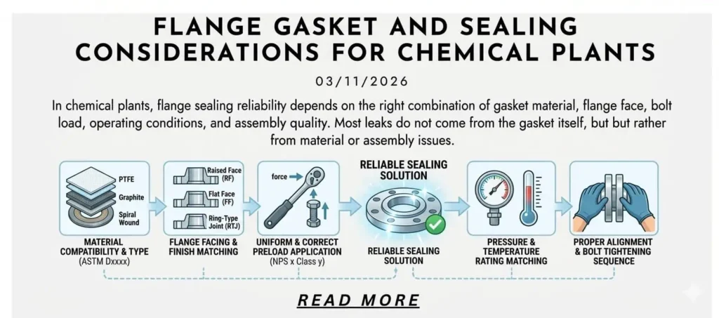
In chemical plants, flange sealing reliability depends on the right combination of gasket material, flange facing, bolt load, operating conditions, and assembly quality. Most leaks do not come from gasket type alone. In real service, leakage usually starts when the gasket, flange face, bolting, and process condition stop working as one system. A gasket that looks correct on the datasheet can still fail if the joint sees thermal cycling, wet shutdown exposure, flange face damage, or uneven bolt stress.
That is why gasket selection in chemical plants should never be treated as a simple purchasing decision. The correct choice must match the media, pressure, temperature, facing type, maintenance practice, and the consequence of leakage. In corrosive service, the sealing decision also needs to stay aligned with flange material selection, corrosion mechanism review, and joint assembly quality.
Field rule: In chemical service, a “good gasket” does not create a reliable joint by itself. A reliable joint comes from the correct gasket, the correct flange face, the correct preload, and the correct service assumptions working together.
| Sealing Factor | Why It Matters |
|---|---|
| Gasket material | Must resist the process media and remain stable through pressure and temperature changes. |
| Flange facing | Controls how the gasket seats and how load is distributed across the sealing area. |
| Bolting and preload | Determines whether the gasket reaches and maintains sealing stress. |
| Service conditions | Startup, shutdown, cleaning, and thermal cycling often control real leak behavior. |
| Assembly quality | Poor surface preparation, misalignment, or incorrect tightening can defeat even the right gasket. |

If you are reviewing this topic as part of a wider chemical plant materials strategy, it also helps to read How to Select Flange Materials for Chemical Processing, Inconel vs Stainless Steel for Corrosive Environments, and Corrosion Mechanisms in Process Piping Systems. Those three topics explain the body material, corrosion risk, and alloy upgrade logic that sit behind sealing decisions.
Why Flange Joints Leak in Chemical Plants
Why Chemical Plant Flange Sealing Is More Demanding Than General Industrial Service
Chemical plant flange joints are exposed to a much harsher combination of conditions than general utility service. Corrosive media, thermal cycling, shutdown moisture, flushing chemicals, pressure variation, and leak consequence all raise the sealing requirement. A water line gasket selection method is often too optimistic for chemical service because chemical plants are less forgiving when the joint loses preload or when a small leak reaches the atmosphere.
Flanges are also more vulnerable than plain pipe because the joint includes a gasket interface, a machined face finish, bolting, and crevice geometry. These details create localized stress and localized chemistry. In many services, the first leak path is not through the pipe wall. It is across the flange face or under the gasket after the joint loses sealing stress.
The Most Common Leakage Causes at Flanged Joints
In field work, repeated flange leakage usually comes back to a short list of root causes:
- Gasket material incompatible with the process media
- Wrong gasket style for the pressure-temperature range
- Incorrect pairing between gasket type and flange facing
- Insufficient or uneven bolt preload
- Flange face damage, corrosion, distortion, or poor alignment
- Gasket creep or relaxation after temperature cycling
- Reuse of damaged gaskets or worn fasteners
- Leakage triggered during startup, shutdown, or cleaning rather than steady operation
The important point is that most chemical plant leakage events are system mismatches. They are rarely explained by “the gasket was bad” and nothing else.
Why Leakage Often Starts at Shutdown, Startup, or Cleaning — Not During Normal Operation
Many joints hold during steady-state production and then begin to seep after temperature changes, cleaning cycles, or maintenance outages. This happens because shutdown can create wet crevices, trapped residue, condensate formation, and relaxation of bolt load. During startup, thermal expansion can shift flange alignment and stress distribution before the joint stabilizes.
Engineering example: a PTFE-based gasket may appear stable during continuous operation, then show light seepage after cooling because the joint loses seating stress as the system contracts. In that situation, the leak is driven by joint behavior during transition, not by chemical attack alone.

Practical takeaway: If a flange leaks only after shutdown or restart, do not assume the media compatibility review was wrong. Check preload retention, thermal movement, trapped fluid, and the tendency of the gasket material to relax after cycling.
Gasket Types and Where They Fit
Soft Gaskets
Soft gaskets are commonly used where good conformity, chemical compatibility, and lower seating stress are important. This family includes PTFE sheet, modified PTFE, expanded PTFE, compressed non-asbestos sheet, and flexible graphite sheet. In chemical plants, soft gaskets are especially common in corrosive liquid service, lined systems, lower-pressure chemical lines, and equipment nozzles where the flange load is limited.
The main advantage of soft gaskets is their ability to conform to real flange surface conditions. The main limitation is that some of them are more sensitive to creep, cold flow, blowout resistance, and long-term load retention than semi-metallic or metallic options. When nonmetallic gasket properties need to be specified formally, ASTM F104 is commonly used as the classification framework.
Semi-Metallic Gaskets
Semi-metallic gaskets are widely used where pressure, temperature, and cycling are more demanding. The most common examples are spiral wound gaskets and kammprofile gaskets. In chemical plants, these gaskets are often preferred for raised-face flanges in higher-duty service because they combine resilience with better blowout resistance and better recovery than many soft gasket materials.
They are not universal answers. They still depend heavily on correct flange facing, correct seating stress, and correct filler selection. A spiral wound gasket with PTFE filler behaves differently from one with graphite filler, even though the metal winding design looks similar. Practical filler and ring guidance can be checked against spiral wound gasket selection guidance.
Metallic Ring Joint Gaskets
Ring Type Joint gaskets are used where pressure is high, leak consequence is high, and the flange design is built around a machined groove rather than a flat or raised-face seating area. RTJ joints are common in demanding oil and gas service, but they can also appear in chemical plants where sealing integrity requirements are unusually high.
The key point is that RTJ is not “better” in every application. It is a different sealing logic. If the flange is not designed for RTJ and the service does not justify it, using an RTJ-style approach does not improve the joint.
Quick Selection View by Service Pattern
| Service Pattern | Common Gasket Direction | Typical Watch-Out |
|---|---|---|
| Corrosive liquid, lower pressure | PTFE, modified PTFE, expanded PTFE | Creep and load relaxation |
| Hot chemical service | Graphite sheet, spiral wound with graphite filler | Oxidizing conditions and face condition |
| Pressure and thermal cycling | Spiral wound or kammprofile | Facing compatibility and bolt-up quality |
| High-consequence high-pressure service | RTJ or engineered metallic sealing solution | Correct flange design and groove condition |
| Lined equipment or low-load joints | Soft gasket families | Over-tightening and flange distortion |

Gasket Material Selection by Chemical Service
PTFE and Modified PTFE for Corrosive Chemical Service
PTFE is widely chosen for chemical compatibility. That makes it one of the most common gasket materials in corrosive liquid service. It is especially attractive where the media attacks many elastomeric or fiber-based alternatives. In plants handling aggressive chemicals, PTFE often becomes the starting point for gasket review.
But PTFE is not a universal answer. Pure PTFE can be vulnerable to creep and cold flow under sustained compressive load, especially when the joint sees temperature change or long-term stress relaxation. Modified PTFE or filled PTFE products can help improve load retention, but the real decision still depends on the service pattern. For a practical material reference, see modified PTFE and reduced creep / cold flow guidance.
Engineering example: on a low-pressure corrosive dosing line, pure PTFE may appear ideal on chemical resistance alone, yet repeated warm-cold cycles can still produce light leakage if the joint cannot maintain stress. In these cases, the sealing problem is mechanical as much as chemical.
Graphite Gaskets for High Temperature Service
Graphite becomes more attractive when temperature, pressure fluctuation, and recovery matter as much as chemical compatibility. In hot service, graphite-filled or graphite-sheet solutions often give better sealing stability than PTFE-based materials. They are commonly used in steam, hot hydrocarbon, and elevated-temperature process service, including chemical plants.
The limitation is that graphite is not a universal chemical solution either. Oxidizing environments and certain service details can change how comfortable the choice really is. That is why graphite should be selected for the full service pattern, not just for temperature alone.
Spiral Wound with PTFE vs Graphite Filler
This is a common decision point in chemical plants. A spiral wound gasket with PTFE filler is often favored where chemical compatibility is the primary driver and operating temperature is moderate. A spiral wound gasket with graphite filler is often favored when heat, cycling, and load recovery are more important.
Users often ask which filler is “better.” That is the wrong question. The correct question is what the service demands from the filler. A PTFE-filled spiral wound may win on chemistry. A graphite-filled spiral wound may win on thermal stability and recovery. The correct choice depends on which failure mode is more likely to drive leakage.
Acid, Chloride, Solvent, and Mixed-Chemical Services
Different media families create different gasket priorities:
- Acid service: chemical compatibility is the first screen, but temperature and concentration can shift the gasket decision significantly.
- Chloride-bearing service: the gasket has to work with flange material and localized corrosion risk, especially at the gasket interface.
- Solvent service: swelling, extraction, and long-term material stability become more important.
- Mixed chemical service: gasket selection should be conservative because real plant chemistry is often less clean than the design name suggests.
When the service itself is still being defined, it helps to step back and review how to select flange materials for chemical processing and corrosion mechanisms in process piping systems. Gasket choice should follow the real chemical environment, not just the name on the line list.
Flange Facing, Surface Condition, and Why They Matter
RF, FF, and RTJ Faces Do Not Use the Same Sealing Logic
Raised Face, Flat Face, and Ring Type Joint flanges do not seal the same way, so gasket selection cannot be separated from facing type. A gasket that performs well on a raised-face flange is not automatically the right choice for a flat-face flange, and RTJ joints rely on a completely different seating geometry.
If you want to understand why face type changes gasket behavior, it is worth reviewing RF vs FF vs RTJ flanges. In practice, facing type controls how load is transmitted, how the gasket is confined, and how sensitive the joint becomes to distortion or over-tightening.

Surface Finish, Damage, and Reuse Problems
Even the correct gasket can fail if the flange face is scratched, pitted, distorted, or out of alignment. In corrosive chemical service, face condition matters even more because localized corrosion often appears first in the sealing zone. If the face is damaged, the gasket may never develop uniform stress, no matter how carefully the joint is assembled.
Reused gaskets create another common problem. A gasket that has already taken compression set or has already been chemically exposed should not be assumed to behave like a new one. Reuse often turns a controlled sealing problem into a guess.
Why a Good Gasket Still Fails on a Bad Flange Face
Engineering example: a spiral wound gasket is replaced twice on the same process nozzle, but leakage returns after each restart. The gasket is blamed first. Inspection later shows the real problem is flange face scoring and minor rotation under bolt-up. The gasket was never the primary failure source. The joint geometry was.
This is one of the most important field lessons in chemical plant sealing work: a good gasket cannot correct a bad flange face.
Bolting, Load, and Assembly Quality
Gasket Selection Is Useless If Bolt Load Is Wrong
The gasket needs enough seating stress to seal, and enough retained stress to stay sealed after pressure, temperature, and time begin working against the joint. Under-tightening can leave leakage paths from the start. Over-tightening can crush the gasket, distort the flange, or damage soft materials. Uneven tightening is just as serious because it creates non-uniform stress around the gasket circumference.
For this reason, gasket selection and bolt load should always be reviewed together. A material upgrade does not solve a preload problem.
Why Assembly Practice Matters More Than Many Buyers Expect
Assembly quality is where many otherwise reasonable sealing decisions fail. In chemical plants, controlled bolt tightening sequence, lubrication practice, face inspection, alignment checks, and replacement discipline all matter. The joint has to be assembled as a pressure boundary, not as general mechanical hardware.
ASME PCC-1 is important here because it provides guidance for pressure-boundary bolted flange joint assembly and helps turn experience-based tightening into a repeatable assembly method with better leak-tightness control.

For a broader assembly discussion, this article is a strong companion reference: Flange Assembly: 4 Steps to Zero-Leakage Joint Integrity.
Common Assembly Mistakes
- No inspection of flange face before assembly
- Wrong tightening sequence
- Mixed bolt conditions or poor lubrication control
- Wrong gasket thickness or wrong gasket size
- Reusing damaged gaskets
- Assuming the same tightening method works for every gasket family
- Ignoring retightening logic where procedure requires it
Practical takeaway: In repeated leak cases, review bolting practice before assuming the gasket chemistry was wrong. Assembly quality often decides whether the selected gasket ever had a fair chance to work.
Failure Patterns and Real Chemical Plant Scenarios
Case 1 — PTFE Gasket Seepage After Thermal Cycling
Problem: the joint stayed dry during stable production but began to seep after cool-down and restart.
Likely cause: loss of seating stress after thermal cycling and gasket relaxation.
Correction: review whether modified PTFE, a semi-metallic gasket, or a different preload strategy is better suited for the service.
Case 2 — Spiral Wound Gasket Failure Caused by Bad Flange Face Condition
Problem: the gasket was replaced, but leakage repeated on the same flange.
Likely cause: flange face scoring, minor distortion, or alignment error prevented uniform seating.
Correction: inspect and repair the face condition, then reassemble with the correct seating method.
Case 3 — Chloride Service Leakage at Instrument Branch Flange
Problem: the main line remained stable, but a small branch flange leaked repeatedly.
Likely cause: low flow, trapped fluid, crevice conditions, and localized corrosion at the gasket area.
Correction: review branch configuration, gasket choice, flange material, and the likelihood of shutdown wetting. This is where corrosion mechanisms in process piping systems becomes directly relevant.
Case 4 — High-Consequence Hazardous Chemical Service Upgraded to a More Conservative Sealing Design
Problem: conventional sealing worked on paper, but the leak consequence was too high for a low-margin solution.
Likely cause: the original sealing design did not provide enough tolerance for real-world operating variation.
Correction: move to a more conservative gasket and joint design, and in some cases review whether the flange material itself should also be upgraded. This is where Inconel vs Stainless Steel for Corrosive Environments can become part of the decision.
How to Choose the Right Gasket and Sealing Strategy
Step 1 — Define the Real Service
- Process media and concentration
- Impurities and solids
- Operating and upset pressure-temperature range
- Wet or dry shutdown condition
- Cleaning and flushing exposure
- Leak consequence
Step 2 — Match the Gasket Family to the Service Pattern
- Chemical resistance need
- Temperature need
- Facing type
- Required seating stress
- Recovery requirement after cycling
- Maintenance accessibility
Step 3 — Check the Full Joint, Not Just the Gasket
- Flange material
- Flange face condition
- Bolting condition and preload method
- Alignment and joint geometry
- Assembly discipline
- Field leakage history
Step 4 — Screen the Decision Against Lifecycle Risk
- Downtime cost
- Safety consequence
- Environmental consequence
- Maintenance frequency
- Spare part availability
- Probability of repeat leakage
Practical Checklist for Chemical Plant Flange Sealing
Questions to Answer Before Choosing a Gasket
- What is the actual media, not just the line name?
- Is the service steady, cyclic, or shutdown-sensitive?
- Is the flange RF, FF, or RTJ?
- Is localized corrosion expected at the gasket interface?
- Does the joint need chemical resistance, temperature resistance, or both?
- Is the leakage consequence high enough to justify a more conservative sealing design?
What to Check Before Assembly
- Flange face condition
- Alignment
- Correct gasket type and size
- Correct bolting and lubrication practice
- Tightening sequence and load control
- Replacement of worn or damaged sealing components
What to Review After Repeated Leakage Events
- Wrong gasket family for the real service
- Wrong service assumption
- Preload loss
- Flange face damage
- Thermal cycle effects
- Shutdown wetting and crevice conditions
| Review Area | Typical Field Question |
|---|---|
| Media and chemistry | Did the gasket really match the actual chemical exposure, including cleaning and shutdown? |
| Gasket family | Was the chosen gasket designed for the real pressure-temperature pattern? |
| Facing and surface | Was the flange face condition good enough for the gasket to seal properly? |
| Bolting | Did the joint reach and maintain the intended preload? |
| Transition conditions | Did the leak start during shutdown, cooling, or restart rather than normal operation? |
In chemical plants, gasket selection should be treated as a sealing system decision, not a gasket catalog decision. The most reliable joints are built by matching the real service to the right gasket family, the right flange face, the right bolt load, and the right assembly practice. That is also why sealing choices should stay connected to body material selection, corrosion mechanism review, and maintenance planning.
If the service involves corrosive media, flange material upgrades, or repeated leakage history, these related guides should stay in the same topic path: How to Select Flange Materials for Chemical Processing, Inconel vs Stainless Steel for Corrosive Environments, Corrosion Mechanisms in Process Piping Systems, and questions to ask a flange supplier before RFQ.
FAQ
What is the most important factor in chemical plant flange sealing?
The most important factor is joint compatibility as a whole.
The gasket, flange face, bolt load, temperature cycle, and process media must all work together. A chemically resistant gasket alone does not guarantee leak-free service.
Is PTFE always the best gasket material for corrosive chemical service?
No.
PTFE offers strong chemical compatibility, but it is not always the best choice for thermal cycling, long-term load retention, or high seating stress applications. Modified PTFE, graphite, or semi-metallic designs may be more stable depending on the service pattern.
Why do flange joints often leak after shutdown instead of during normal operation?
Because shutdown changes the joint condition.
Cooling, moisture, trapped chemicals, condensate, and bolt stress relaxation can create leakage paths that were not active during steady operation.
Can a better gasket solve a damaged flange face?
Usually not.
A badly scratched, corroded, or distorted flange face often prevents uniform gasket seating. In that situation, replacing the gasket alone usually does not solve the real problem.
When should the flange material itself be reviewed during a sealing problem?
Review the flange material when the leak pattern suggests localized corrosion, chloride attack, or repeated damage at the sealing interface.
In those cases, gasket replacement may not be enough, and the flange body material may need to be reviewed together with the corrosion mechanism and service severity.