Orifice Flange Assembly & Manufacturing:Precision Flow Measurement Solutions / ASME B16.36
Our Orifice Flanges are engineered specifically for flow rate metering of liquids, gases, and steam in industrial pipelines. Unlike standard flanges, an orifice flange assembly is designed to house an orifice plate and facilitate the measurement of differential pressure.
Manufactured in strict accordance with ASME B16.36 standards, our flanges ensure accurate flow data transmission. We supply complete orifice flange sets (unions) to the oil & gas, petrochemical, and power generation industries, available in Carbon Steel, Stainless Steel, and Exotic Alloys.
Types of Orifice Flange We Supply
 Stainless Steel Flanges
By Design Type
By Standard & Class
Advanced Materials
Weld Neck Orifice Flange (WN)
The weld neck orifice flange is the most common choice for high-pressure and high-temperature applications. It is butt-welded to the pipe, providing superior structural integrity and reducing turbulence at the orifice plate.
*Best for: Critical metering runs and severe service conditions.
Slip-On Orifice Flange (SO)
The slip-on orifice flange slides over the pipe end and is welded both inside and out. It is a cost-effective alternative to weld necks for lower pressure classes (typically Class 150 or Class 300).
*Best for: Moderate pressure applications where cost and ease of alignment are priorities.
Threaded Orifice Flange
Used in scenarios where welding is hazardous or not permitted. These are typically used in smaller pipe sizes or specific instrument lines.
Key Design Features & Components
An orifice flange union differs from standard pipe flanges due to specific machining requirements necessary for flow measurement.
Flow Metering Taps: Each flange features a pair of pressure tap holes, machined radially into the flange ring. These flange taps allow the connection of a transmitter or gauge to measure the pressure drop across the orifice plate.
Jack Screw Assembly: A critical feature for maintenance. The jack screw in the orifice flange is used to force the flanges apart, allowing for the safe and easy insertion or removal of the orifice plate without springing the pipeline.
Complete Assembly: Our sets typically include the flange pair, jack screws, nuts, bolts, and gaskets.
What is ASME B16.5 Flange?
ASME B16.5 is the authoritative industrial standard for Pipe Flanges and Flanged Fittings. It covers nominal pipe sizes from NPS 1/2 through NPS 24 and pressure ratings from Class 150 to Class 2500. The standard specifies detailed requirements for dimensions, pressure-temperature ratings, materials, tolerances, marking, and testing, ensuring the interchangeability and sealing integrity of piping, valves, and fittings.
| Feature | Specification Details |
| Standard | ASME B16.36 (Orifice Flanges), ASME B16.5 (Dimensions) |
| Pressure Classes | Class 300, 600, 900, 1500, 2500 (Class 150 available) |
| Size Range | 1″ to 24″ (Custom sizes up to 48″ available) |
| Facing Types | Raised Face (RF), Ring Type Joint (RTJ) |
| Tap Size | Standard 1/2″ NPT (Other sizes upon request) |
| Materials | Carbon Steel: A105, A350 LF2 Stainless Steel: A182 F304/L, F316/L Alloy: Duplex, Inconel, Monel |
Applications and Industries
Our orifice flange assemblies are the industry standard for flow measurement in:
Oil & Gas: Custody transfer and wellhead flow monitoring.
Chemical Processing: Precise dosing and fluid control.
Water Treatment: Filtration flow rates and restriction orifice applications.
Power Generation: Steam flow monitoring in high-pressure lines.
Video Resource
For a visual demonstration of how these components are inspected and assembled in a manufacturing context, see: Orifice flange assembly inspection in detail
This video is relevant as it visually details the specific inspection points, ASME standards, and parts (like the jack screw and tap holes) discussed in the content, reinforcing the manufacturing expertise claimed in the text.
Related blog
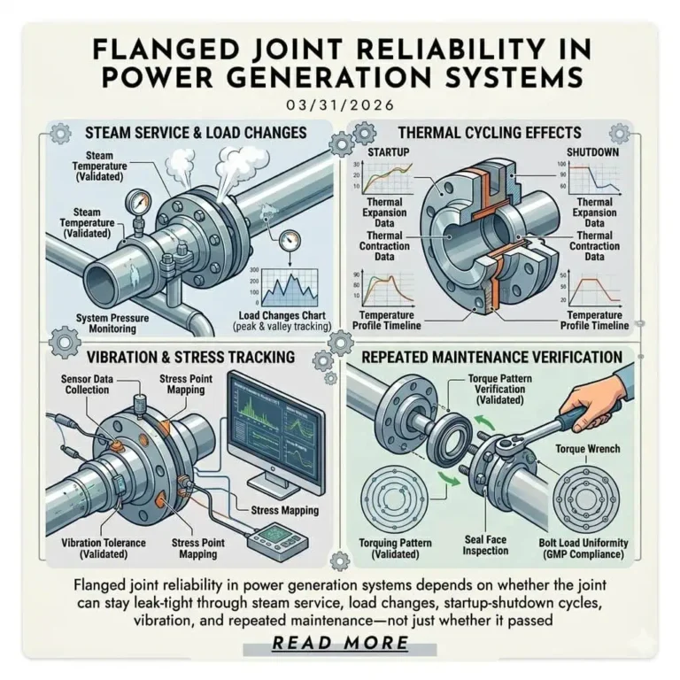
Flanged Joint Reliability in Power Generation Systems

Thermal Cycling Effects on Flanged Joints: Causes of Leakage and Design Checks
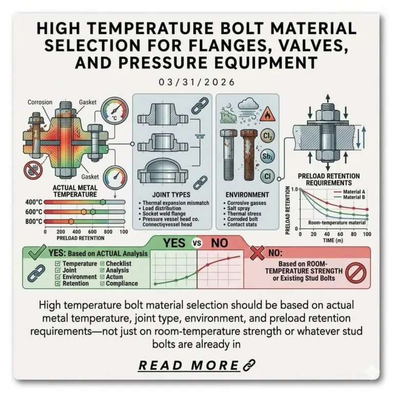
High Temperature Bolt Material Selection for Flanges, Valves, and Pressure Equipment

Documentation and Traceability for High Purity Components: What Engineering and QA Should Check
FAQ
What is the difference between an orifice flange and a normal flange?
The primary difference is that Orifice Flanges are designed for metering flow, whereas normal flanges are used solely for connecting pipes. While they may have similar outer dimensions, they differ in three key structural areas:
Pressure Taps: Orifice flanges feature radial holes (typically 1/2″ NPT) drilled through the flange ring to measure differential pressure. Normal flanges do not have these.
Jack Screws: Orifice flanges are equipped with jack screws to mechanically separate the flange faces for maintenance. Normal flanges lack this feature.
Thickness & Standard: Orifice flanges follow ASME B16.36 and are often thicker (especially in lower pressure classes like Class 300) to accommodate the tap holes without sacrificing strength. Normal flanges follow ASME B16.5.
What is the purpose of the jack screw in an orifice flange?
The Jack Screw is a critical maintenance tool designed to facilitate the safe removal and replacement of the orifice plate.
Over time, corrosion or high pressure can cause the gaskets and flange faces to bond. The jack screw (located 90° from the pressure taps) is mechanically driven into the assembly to force the two flanges apart against the bolt tension. This creates a sufficient gap to slide the orifice plate and gaskets out without damaging the flange sealing faces or requiring wedges that could spark or mar the metal.
Where are the taps located on an orifice flange?
Orifice flange taps are located to satisfy the “Flange Taps” configuration defined by ASME B16.36 and ISO 5167.
Operational Location: When installed, the center of the tap hole is exactly 1 inch (25.4 mm) upstream and 1 inch (25.4 mm) downstream from the face of the orifice plate.
Manufacturing Location: To achieve this installed dimension, manufacturers drill the tap hole center 15/16 inch (23.8 mm) from the flange’s raised face. This accounts for the standard 1/16 inch (1.6 mm) gasket thickness used in the assembly (15/16″ + 1/16″ = 1″).
What is included in an orifice flange set?
An Orifice Flange Set (often called a Union) is a complete assembly required for a differential pressure measurement point. It typically includes:
Two Flanges: Usually Weld Neck (WN) style with machined taps.
Orifice Plate: The primary flow restriction element.
Two Gaskets: Often precision-cut to prevent interference with the taps.
Two Jack Screws: For spreading the flanges.
Bolts (Studs) & Nuts: These are often longer than standard flange bolts to accommodate the plate and double gaskets.
Pipe Plugs: Two plugs to seal the tap holes during transport or if unused.
What is the standard for orifice flange dimensions?
The governing standard for the dimensions and tolerances of orifice flanges is ASME B16.36 (Orifice Flanges).
Scope: This standard covers flanges connecting to orifice pressure differential connections.
Pressure Ratings: It references ASME B16.5 for pressure-temperature ratings and material requirements.
Important Note: ASME B16.36 does not cover Class 150 flanges because they are generally too thin to accommodate the drilling of pressure taps without compromising structural integrity. Consequently, Class 300 orifice flanges are typically used in Class 150 piping systems.