








Technischer Leitfaden für Sauerstoffsensoren
Vergleichen Sie Position, Funktion, Scan-Daten und Kaufanforderungen von stromaufwärts und stromabwärts gelegenen Sauerstoffsensoren, ohne Sensor 1 und Sensor 2 zu verwechseln.
Kurze Antwort
Ein vorgeschalteter Sauerstoffsensor ist vor dem Katalysator eingebaut und unterstützt üblicherweise die Kraftstoffrückkopplung. Ein nachgeschalteter Sensor ist nach dem Katalysator eingebaut und unterstützt üblicherweise die Katalysatorüberwachung. Vor dem Katalysator bedeutet normalerweise Sensor 1 und nach dem Katalysator Sensor 2, aber die genaue Bank, Position und das Teil müssen anhand von Fahrzeugservice- oder Passdaten bestätigt werden.
Vor- und nachgelagerte Bereiche auf einen Blick
| Frage | Vorgeschalteter Sensor | Nachgeschalteter Sensor |
|---|---|---|
| Typische Position | Vor dem Katalysator | Nach dem Katalysator |
| Allgemeine Positionsbezeichnung | Sensor 1 / Vorkat / vorne | Sensor 2 / Nachkat / hinten |
| Primäre Strategie | Gemischrückführung und Kraftstoffregelung | Rückmeldung der Katalysatorüberwachung |
| Erwartete Daten | Hängt stark von der Schmalband- oder Breitbandtechnologie ab | Oft stabiler als der vordere Sensor, wenn der Katalysator arbeitet, aber die Fahrzeugstrategie variiert. |
| Kaufrisiko | Falsche Kalibrierung, Stecker oder Bank. | Falsche Kabellänge, Verlegung, Stecker oder Position. |
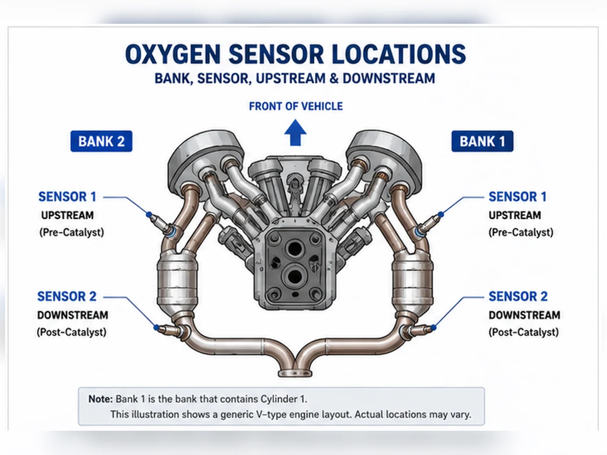
Bezeichnung von Front, Heck, Bank und Sensor
“Vorne” und “Hinten” können bei quer eingebauten Motoren oder Systemen mit mehreren Katalysatoren mehrdeutig sein. Verwenden Sie nach Möglichkeit die Bank- und Sensoridentifikation. Bank 1 enthält Zylinder 1. Sensor 1 ist der Sensor vor dem Katalysator für diese Bank; Sensor 2 ist der nachgeschaltete. Einige Fahrzeuge haben zusätzliche Sensoren oder eine andere Terminologie, daher bleibt die Serviceinformation maßgeblich.
Warum Scandaten anders aussehen sollten
Ein konventioneller schmalbandiger vorgeschalteter Sensor kann während des Closed-Loop-Betriebs zwischen fett und mager wechseln. Ein Breitbandsensor wird anders dargestellt und kann als Strom, Lambda oder Solläquivalent angezeigt werden. Ein nachgeschaltetes Signal wird in Bezug auf die Katalysatorfunktion interpretiert. Der Vergleich zweier Diagramme ohne vorherige Identifizierung von Technologie und Betriebsbedingungen kann zu einer Fehldiagnose führen.
Codes, die eine Position erwähnen
Ein positionsspezifischer Code grenzt den zu prüfenden Stromkreis ein; er beweist nicht, dass das Messelement defekt ist. Überprüfen Sie Stecker und Kabelbaum, Heizungsstrom und Masse, Abgasleckage und Betriebsdaten. P0420 oder P0430 sollten nicht als Anweisung zum Austausch des nachgeschalteten Sensors behandelt werden.
Können vor- und nachgelagerte Sensoren ausgetauscht werden?
Gehen Sie nicht von Austauschbarkeit aus. Zwei Sensoren können die gleiche Gewindegröße oder Steckeroptik haben, sich aber in Technologie, Kalibrierung, Kabellänge, Schutzschild oder Steckerkodierung unterscheiden. Stimmen Sie mit der OE-Referenz und dem genauen Fahrzeug, Motor, Markt/Emissionspaket, Bank und Position überein.
Checkliste zur Positionsüberprüfung
- Lesen Sie die vollständige Codebeschreibung und die Standbilddaten.
- Identifizieren Sie Zylinder 1 und Bank 1 anhand der Serviceinformationen.
- Abgasströmung verfolgen, um Positionen vor und nach dem Katalysator zu unterscheiden.
- Stecker, Kabellänge und Verlegeclips vergleichen.
- Vor der Bestellung die OE-Referenz und Sensortechnologie bestätigen.
Die Positionsidentität steht vor der Signalinterpretation
Upstream und Downstream beschreiben die Position relativ zu einem Katalysator, nicht eine universelle physikalische Richtung am Fahrzeug. Bei einem Zweibank-Motor kann jede Bank ihren eigenen Sensor 1 und Sensor 2 haben. Einige Abgasanlagen fügen weitere Katalysatoren oder Sensoren hinzu. Vor dem Test die Zylindernummerierung bestätigen, den Abgasweg verfolgen und den Code oder Datenbezeichner mit dem physischen Stecker abgleichen.
| Eingangskennung | Upstream-Entscheidung | Downstream-Entscheidung |
|---|---|---|
| Zylinder und Bank | Sensor 1 an der Bank mit den genannten Zylindern lokalisieren | Sensor 2 nach dem überwachten Katalysator dieser Bank lokalisieren |
| Abgasstrom | Vor dem relevanten Katalysator | Nach dem relevanten Katalysator |
| Katalogdaten | Muss genaue Bank/Position und Technologie angeben | Muss genaue Position, Leitungsführung und Stecker angeben |
| Systemdiagramm | Bestätigt physischen Steckverbinder und Kabelbaumverlauf | Verhindert Verwechslungen mit zusätzlichen Nach-Katalysator-Sensoren |
Wie sich ihre Steuerungsrollen unterscheiden
Vorgeschaltete Rückmeldung
Nach Erfüllung der Freigabebedingungen verwendet das Steuergerät die vorgeschaltete Rückmeldung mit Luftmassenstrom, Last, Temperatur und anderen Eingängen, um das Gemisch zu bewerten. Ein schmalbandiger Sensor kann um seinen Regelpunkt schalten, während ein breitbandiger Sensor als Strom, Lambda oder Verbrennungsluftverhältnis dargestellt werden kann. Eine magere Meldung kann ein genauer Hinweis auf ungemessene Luft oder geringe Kraftstoffzufuhr sein, nicht auf einen defekten Sensor.
Nachgeschaltete Überwachung
Der nachgeschaltete Sensor hilft dem Steuergerät üblicherweise, das Sauerstoffspeicherverhalten des Katalysators zu bewerten. Sein Signal wird in Bezug auf das vorgeschaltete Signal und definierte Überwachungsbedingungen interpretiert. Ein hinterer Sensor wird nicht einfach eine feste Spannung zeigen, und ein Katalysatorcode beweist nicht, dass der hintere Sensor ersetzt werden sollte.
Strategieausnahmen
Hersteller können Downstream-Informationen für zusätzliche Anpassungen oder Diagnosen nutzen. Die üblichen Rollen dienen der Orientierung, nicht der Berechtigung, die Logik eines Fahrzeugs auf ein anderes zu verallgemeinern. Verwenden Sie genaue Serviceinformationen für das Fahrzeug, den Motor, das Abgasnachbehandlungssystem und die Kalibrierung.
Signale nur unter gültigen Bedingungen vergleichen
| Zustand | Upstream-Beobachtung | Downstream-Beobachtung | Einschränkung |
|---|---|---|---|
| Kaltstart | Bietet möglicherweise noch keine Rückkopplung im geschlossenen Regelkreis | Katalysatorüberwachung normalerweise nicht bereit | Temperatur- und Freigabebedingungen nicht erfüllt |
| Warmer, stabiler Betrieb | Technologiespezifisches Gemischverhalten | Bewertet anhand des Katalysatorverhaltens | Lecks und Kraftstofffehler können beide verfälschen |
| Beschleunigung | Befohlene Anreicherung kann das Signal verändern | Reaktion kann durch Katalysatorspeicherung verzögert werden | Kein stationärer Vergleich |
| Kraftstoffabschaltung bei Verzögerung | Hoher Sauerstoffgehalt im Abgas kann erwartet werden | Reaktion hängt von Katalysator und Strategie ab | Bezeichnen Sie erwartetes Verhalten nicht als Fehler |
Positionsspezifische Codes als Testpfade verwenden
Sensor-1-Schaltung oder Fehlercodes
Überprüfen Sie die genannte Bank und die vorgeschaltete Schaltung, bewerten Sie aber auch die tatsächlichen Gemischbedingungen. Prüfen Sie die Steckverbinderintegrität, den Heizungsbetrieb, die Referenz- oder Signalmasse, Abgaslecks vor dem Sensor und die Kraftstoffkorrekturwerte. Ein Reaktionstest muss der Schmalband- oder Breitbandtechnologie entsprechen.
Sensor-2-Schaltung oder Heizungscodes
Bestätigen Sie den Steckverbinder und Kabelbaum nach dem Katalysator, die Unterbodenhitze, Wasser und Stößen ausgesetzt sein können. Testen Sie die Versorgungs-, Steuer- und Signalkreise gemäß den Vorgaben. Ersetzen Sie eine Katalysator-Wirkungsgraddiagnose nicht durch einen direkten Schaltungstest.
P0420 und P0430
Diese Codes betreffen die Effizienz des Katalysatorsystems. Bestätigen Sie, dass keine aktive Fehlzündung, kein Gemischfehler oder Abgasleck vorliegt, validieren Sie beide Sensorsignale und befolgen Sie das Katalysatorverfahren. Der Austausch des nachgeschalteten Sensors ist nur gerechtfertigt, wenn seine eigenen Daten zeigen, dass er nicht korrekt melden kann.
Warum passende Gewinde Positionen nicht austauschbar machen
Vor- und nachgeschaltete Sensoren können sich in der Sensortechnologie, Kalibrierung, Heizungseigenschaften, Schutzabschirmung, Steckerstiftbelegung, Kabellänge und Clips unterscheiden. Selbst wenn ein Teil physisch in beide Buchsen passt, kann das Steuergerät ein anderes elektrisches System erwarten. Verlängern, erzwingen oder schneiden Sie keinen direkt passenden Kabelbaum, um die falsche Position zu erreichen.
| Vergleichsposten | Nachweis erforderlich | Ablehnen, wenn |
|---|---|---|
| OE-Referenz | Aktueller Anwendungsdatensatz für genaue Position | Querverweis ist unbestätigt oder für eine andere Emissionsvariante |
| Technologie | Schmalband, Breitband/Lambda oder spezifizierte Ausführung | Auflistung basiert nur auf der Anzahl der Drähte |
| Stecker | Codierung, Verriegelung und Schaltungszuordnung | Gehäuse ist gezwungen oder Stifte unterscheiden sich |
| Leitung und Klemmen | Korrekte Länge und wärmegeschützte Verlegung | Kabel muss gespannt oder in der Nähe von beweglichen/heißen Teilen belassen werden |
Komplexes Szenario: Ein hinterer Code wird am vorderen Stecker diagnostiziert
Komplexes technisches Szenario: Ein Techniker folgt einer generischen “Heck-Sensor”-Kennzeichnung an einem quer eingebauten Motor und testet den falschen Stecker. Das Abgasdiagramm zeigt, dass der als Bank 1 Sensor 2 bezeichnete Stecker zu einer anderen Seite des Motorraums führt. Die korrekte Positionsidentifikation ändert das Schaltungsergebnis und verhindert den Austausch eines funktionierenden Sensors. Dies ist ein zusammengesetztes Lehrszenario, kein Kundenfall von Sunhyings.
Position vor der Bestellung erfassen
Erfassen Sie die vollständige Codebeschreibung, Motoridentifikation, Markt-/Emissionspaket, Position von Zylinder 1, Bank, Sensornummer, Katalysatorbeziehung, OE-Nummer, Steckergesicht und Kabelführung. Ein Foto sollte sowohl den Kontext als auch den Stecker zeigen. Dieser Datensatz ermöglicht es einem Verkäufer oder Reparateur, die genaue Position zu überprüfen, ohne “vorne” oder “hinten” zu einer Passungsbehauptung zu machen.
Reparatur überprüfen, ohne eine Schlussfolgerung zu erzwingen
Überprüfen Sie nach einer Reparatur von Stromkreis, Sensor, Abgas oder Motor zuerst die physische Installation. Bestätigen Sie, dass der richtige Stecker verriegelt ist, das Kabel von Hitze und Bewegung ferngehalten wird und kein Abgasleck vorhanden ist. Beobachten Sie dann den korrekten stromaufwärtigen oder stromabwärtigen Datenbezeichner unter den vom Hersteller angegebenen Betriebsbedingungen. Die Signale sollten zusammen mit Kraftstofftrimms, Sollzustand und Monitorstatus interpretiert werden.
Ein stromabwärtiges Signal, das gleichmäßiger wird, ist für sich allein kein Beweis dafür, dass ein Katalysator gesund ist, genauso wie ein sich änderndes stromaufwärtiges Signal kein Beweis dafür ist, dass der Sensor korrekt kalibriert ist. Der Monitor muss unter gültigen Bedingungen laufen, und der ursprüngliche Fehler darf nicht zurückkehren. Permanente Codes können bestehen bleiben, bis das Modul einen bestandenen Monitor beobachtet; wiederholtes Löschen des Speichers kann die Bestätigung verzögern statt beschleunigen.
Wenn beide Positionen ungewöhnliche Daten zeigen
Wenn sowohl stromaufwärtige als auch stromabwärtige Messwerte abnormal erscheinen, suchen Sie nach Ursachen, die den gesamten Abgasweg betreffen: Fehlzündung, falsche Kraftstoffzufuhr, Abgasleck, Temperaturprobleme oder nicht unterstützte Scan-Tool-Parameter. Der Austausch beider Sensoren zusammen kann nützliche Hinweise entfernen und die gemeinsame Grundursache dennoch bestehen lassen.
Wenn nur eine Position einen elektrischen Fehler aufweist
Ein positionsspezifischer Unterbrechungs-, Kurzschluss- oder Heizungsfehler sollte mit dem richtigen Schaltplan zurückverfolgt werden. Überprüfen Sie gemeinsame Versorgungen, ohne anzunehmen, dass jeder Sensor dieselbe Sicherung oder Masse verwendet. Testen Sie verdächtige Stromkreise unter Last und schützen Sie den Anschlussitz. Ein Code, der einen Sensor benennt, beweist noch nicht, dass das austauschbare Element der Fehlerpunkt ist.
Vor- und nachgelagert bei gängigen Auspuffanordnungen
Stromaufwärts bedeutet vor dem überwachten Katalysator; stromabwärts bedeutet danach. Die Wörter garantieren nicht, dass ein Sensor physisch vorne oder hinten am Fahrzeug sitzt. Die Verpackung kann einen Vorkatalysatorsensor hinter dem Motor platzieren, und einige Systeme verwenden motornahe Katalysatoren plus zusätzliche Unterflurkatalysatoren. Verfolgen Sie den Abgasstrom und verwenden Sie genaue Serviceinformationen.
| Anordnung | Typische vorgeschaltete Identität | Typische nachgeschaltete Identität | Identifikationsrisiko |
|---|---|---|---|
| Reihenmotor, ein überwachter Katalysator | Sensor 1 vor Katalysator | Sensor 2 nach Katalysator | Zusätzliche Sensoren oder Katalysatorstufen können die Anzahl ändern |
| V-Motor, getrennte Bank-Katalysatoren | B1S1 und B2S1 vor ihren Bank-Katalysatoren | B1S2 und B2S2 nach ihren Bank-Katalysatoren | Bank 1 wird durch Zylinder 1 definiert, nicht durch eine universelle Seite |
| Nahgekoppelter plus Unterboden-Katalysator | Sensor vor dem relevanten überwachten Katalysator | Ein oder mehrere Sensoren können verschiedenen Katalysatorstufen folgen | “Hinten” identifiziert möglicherweise nicht eindeutig Sensor 2 oder Sensor 3 |
| Einzelauspuff nach Zusammenführung zweier Bänke | Bankspezifische Sensoren können vor der Zusammenführung liegen | Ein gemeinsamer nachgeschalteter Sensor kann den kombinierten Pfad überwachen | Bankbezeichnung und physische Rohranzahl stimmen nicht immer mit der Intuition überein |
| Quermotor mit enger Bauraumverpackung | Kann je nach Zylinder-/Auspuffanordnung zur Brandwand oder zum Kühler zeigen | Kann unterhalb des Katalysators oder am Unterboden liegen | Die Kurzbezeichnungen Fahrer/Beifahrer und vorne/hinten können falsch sein |
Steuerungsrolle: Gemischrückführung versus Katalysatorüberwachung
Ein vorgeschalteter Sensor liefert üblicherweise die schnelle Gemischrückmeldung, sobald die Bedingungen für den geschlossenen Regelkreis erfüllt sind. Ein nachgeschalteter Sensor trägt typischerweise zur Überwachung der Sauerstoffspeicherung des Katalysators bei. Dies sind vorherrschende Rollen, keine universelle Erlaubnis, die Servicestrategie zu ignorieren. Einige Steuerungssysteme nutzen die nachgeschaltete Information zur Anpassung oder zusätzlichen Diagnose.
| Entscheidungspunkt | Stromaufwärts / Vorkatalysator | Stromabwärts / Nachkatalysator |
|---|---|---|
| Hauptfrage | Was zeigt der Sauerstoffgehalt im Abgas über die Gemischrückmeldung an? | Wie verhält sich das Gasverhalten nach dem Katalysator unter Überwachungsbedingungen im Vergleich? |
| Gängige Technologie | Schmalband oder Breitband/Lambda, je nach Anwendung | Oft Schmalband, aber die Anwendungsevidenz bestimmt |
| Erwartete Antwort | Technologiespezifisch und allgemein reaktionsschnell auf Gemischänderungen | Interpretiert mit Katalysatorspeicher und vorgelagertem Verhalten |
| Wesentliche Störfaktoren | Ansaug-/Kraftstoff-/Zündungsfehler, Leckage vor dem Sensor, Stromkreis und Temperatur | Vorgeschaltete Fehler, Katalysatorzustand, Lecks, Gemisch, Stromkreis und Überwachungsstatus |
| Austauschfehler | Bestellung nach “vorne” ohne Bank/Technologie | Austausch aufgrund von P0420/P0430 |
Signalinterpretation ändert sich mit Technologie und Betriebszustand
Ein warmer schmalbandiger Zirkonoxid-Vorkat-Sensor kann während der Closed-Loop-Korrektur um seinen Regelpunkt pendeln. Ein Breitband-/A/F-Sensor kann als Pumpstrom, Lambda, Äquivalenzverhältnis oder herstellerspezifischer Wert angezeigt werden. Beide sollten nicht nach dem gleichen Spannungsmuster beurteilt werden. Ein schmalbandiges Heck-Signal wird durch die Sauerstoffspeicherung des Katalysators und die Überwachungsstrategie geformt, daher ist auch ein Mythos einer festen Spannung unsicher.
| Betriebszustand | Upstream-Beobachtung | Downstream-Beobachtung | Interpretationsgrenze |
|---|---|---|---|
| Kaltstart | Möglicherweise noch kein aktives Feedback | Katalysatorüberwachung normalerweise nicht bereit | Heiz- und Temperaturfreigabebedingungen sind relevant |
| Warmlaufen | Gemischrückmeldung kann aktiv sein | Niedriger Durchfluss und kleine Lecks können die Messung beeinflussen | Leerlauf allein ist kein vollständiger Systemtest |
| Konstante Fahrt | Kraftstoffkorrektur und -reaktion können bewertet werden | Katalysatorvergleich kann sinnvoll sein, wenn aktiviert | Geschwindigkeit, Last und Temperatur müssen stabil sein |
| Beschleunigung | Die gesteuerte Anreicherung kann das Signal verändern | Die Reaktion kann durch Katalysatorspeicherung verzögert werden | Kein stationärer Katalysatorvergleich |
| Kraftstoffabschaltung bei Verzögerung | Hoher Sauerstoffgehalt im Abgas ist zu erwarten | Das Verhalten hängt von Speicherung und Strategie ab | Ein erwartetes Ereignis sollte nicht als Fehler gekennzeichnet werden |
Positionsspezifische Diagnosekarte
| Bedenken | Schwerpunkt vorgelagerter Test | Schwerpunkt nachgelagerter Test | Gemeinsame Prüfungen |
|---|---|---|---|
| Nieder-/Hochsignal | Tatsächliches Gemisch, Gemischanpassungen und Referenzschaltung | Signalkreis, Lecks und Nachkatalysator-Kontext | Steckverbinder, Technik und genaue Position |
| Langsame Reaktion | Gültige Spezifikation für fett/mager-Stimulus und -Antwort | Überwachungsverfahren und Katalysatoreinfluss | Temperatur-, Kontaminations- und Scandatengrenzen |
| Heizungscode | Geschützte Versorgungs-/Steuerungs- und stromaufwärtige Kabelbaumführung | Exposition des Unterbodenkabelbaums und gemeinsame Versorgung | Belastungstest, Stifte und spezifizierter Widerstand/Strom |
| P0420/P0430 | Gemischregelung und stromaufwärtige Gültigkeit | Gültigkeit des hinteren Sensors im Katalysatorpfad | Fehlzündungen, Lecks, Kontamination und Katalysatorverfahren |
| Hoher Kraftstoffverbrauch | Mögliche direkte Auswirkung durch verzerrtes Feedback | Normalerweise nicht der erste Verdacht bei Kraftstoffregelung | Tatsächlichen Kraftstoffverbrauch und konkurrierende Ursachen bestätigen |
Warum vor- und nachgelagerte Teile ähnlich aussehen, aber nicht austauschbar bleiben
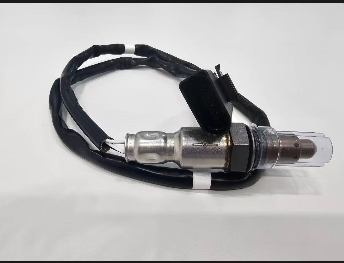
Zwei Sensoren können dasselbe Gewinde und sogar ein ähnliches Gehäuse teilen, sich jedoch in Sensortechnologie, Kalibrierung, Heizung, Steckerkodierung, Anschlussbelegung, Kabellänge, Clips und Abschirmung unterscheiden. Ein längeres Kabel ist nicht automatisch ein sicherer Ersatz; ein unverlegtes Kabel kann Abgas- oder bewegliche Teile berühren. Ein kürzeres Kabel darf niemals gedehnt oder verlängert werden, um die falsche Position zu erreichen.
| Identitätsmerkmal | Nachweis erforderlich | Unsicherer Kurzschluss |
|---|---|---|
| OE-/Anwendungszuordnung | Aktuelle Quelle für exaktes Fahrzeug, Motor und Position | Ein Querverweis ohne Revision kopiert |
| Technologie | Produkt- und Fahrzeugspezifikation | Drahtzählung |
| Stecker/Pinbelegung | Schlüssel, Pins, Anschlussanordnung und Schaltung | Steckerfarbe oder Zwangssitz |
| Leitung und Klemmen | Länge und zugelassener Verlauf für die genaue Position | Verlängerung, Kürzung oder Bindung von Überschuss in Wärmenähe |
| Abschirmung/Gewinde | Zeichnung oder bestätigte physikalische Spezifikation | Annahme, dass gemeinsames Gewinde die Austauschbarkeit bestätigt |
Komplexfall: Zwei ähnliche Steckverbinder wurden falschen Positionen zugeordnet
Szenario einer zusammengesetzten Werkstatt: Nach Abgasarbeiten setzt ein Fahrzeug positionsspezifische Fehlercodes. Beide Sensoren sind vorhanden und ihre Steckverbinder können zu nahegelegenen Abzweigen geführt werden. Der Techniker gleicht Drahtfarben, Steckeridentifikatoren und Serviceverlegung ab und stellt fest, dass die Stecker vertauscht sind. Die Wiederherstellung der korrekten physischen-zu-Daten-Zuordnung behebt den Konflikt, ohne Sensoren auszutauschen.
Das Szenario zeigt, warum Scan-Etiketten, physische Position und Steckerverlegung übereinstimmen müssen, bevor Daten interpretiert werden. Es handelt sich um ein zusammengesetztes Muster, nicht um eine Sunhyings-Kundenreparatur.
Komplexfall: Ein nachgelagerter Sensor war nicht die automatische Antwort auf P0420
Komplexes Diagnoseszenario: Ein hinterer Sensorgraph erscheint aktiv und ein Katalysatorfehlercode ist gespeichert. Bevor ein hinterer Sensor bestellt wird, findet die Werkstatt ein Abgasleck vor diesem und eine abnormale Kraftstoffkorrektur stromaufwärts. Das Leck und der Gemischfehler werden behoben, die genauen Sensoren werden überprüft und der Katalysatormonitor wird erneut durchlaufen. Eine Teileentscheidung wird zurückgestellt, bis das System unter gültigen Bedingungen getestet werden kann.
Dies verspricht nicht, dass die Reparatur eines Lecks jeden Katalysatorfehlercode korrigiert. Es zeigt die erforderliche Beweiskette, bevor ein nachgeschalteter Sensor oder Katalysator verurteilt wird.
Positionsspezifischer Auftragsdatensatz
- Fahrgestellnummer/YMME, Motor und Markt/Emissionskonfiguration
- Zylinder 1 Quelle, Bankidentität und vollständige Sensornummer
- Position relativ zum exakt überwachten Katalysator
- OE-Referenz und kontrollierte Querverweisrevision
- Schmalband-, Titanoxid- oder Breitband-/A/F-Technologie
- Steckergesicht, Kodierung, Pins, Leitungslänge, Clips, Gewinde und Abschirmung
- Diagnosehinweise, die den Austausch dieser Position unterstützen
Entwerfen Sie einen Reaktionstest, der eine positionsspezifische Frage beantwortet
Vor dem Test die Frage formulieren. Bei einem vorgeschalteten Sensor kann dies sein, ob das gemeldete Gemisch innerhalb der Fahrzeugspezifikation einer kontrollierten Fett/Mager-Änderung folgt. Bei einem nachgeschalteten Sensor kann dies sein, ob der Schaltkreis reagiert und ob sein Verhalten während einer definierten Katalysatorüberwachung plausibel ist. Der Stimulus, der erwartete Parameter, die Zeitskala und die Bestehensgrenze müssen mit der Sensortechnologie und den Serviceinformationen übereinstimmen.
| Testdesignfeld | Upstream-Beispiel | Downstream-Beispiel | Ungültige Verknüpfung |
|---|---|---|---|
| Betriebsbedingung | Warmer geschlossener Kreislauf bei angegebener Drehzahl/Last | Aktivierungsbedingungen für Katalysatorüberwachung | Screenshot bei kaltem Leerlauf |
| Datenkanal | Korrektes Spannungs-/Strom-/Lambda-Element | Benannter hinterer Sensorartikel und vorgelagerte Referenz | Unbeschrifteter generischer Graph |
| Stimulus | Genehmigte kontrollierte Gemischänderung | Herstellerüberwachung oder definiertes Reaktionsverfahren | Zufälliges Gasgeben |
| Störfaktorprüfungen | Lecks, Kraftstoffdruck, Luftstrom und Trimmung | Lecks, vorgeschaltete Plausibilität, Fehlzündungen und Katalysatorzustand | Annahme, dass jede Änderung vom Sensor stammt |
| Fazit | Bestanden/nicht bestanden gemäß exakter Spezifikation | Fortsetzung des Stromkreises/Sensor/Katalysator-Pfads | “Sieht langsam aus” ohne Skala oder Grenzwert |
Wenn ein Diagnosegerät einen Parameter ableitet oder filtert, dokumentieren Sie das Gerät und die Datenbezeichnung. Wenn das Fahrzeug die benötigten Informationen nicht unterstützt, verwenden Sie die OEM-Prüfmethode, anstatt einen universellen Ersatz zu erfinden. Nehmen Sie keine Kraftstoff- oder Luftänderungen vor, die zu unsicheren Abgastemperaturen oder unkontrolliertem Betrieb führen.
Position ändert thermische und leitungsbezogene Belastung
Vorgeschaltete Sensoren können höhere und schneller wechselnde Abgastemperaturen erfassen. Nachgeschaltete Sensoren haben oft längere Unterbodenwege, die Wasser, Straßenschmutz und Kabelbaumbewegungen ausgesetzt sind. Diese Tendenzen helfen bei der Planung der Inspektion, ersetzen jedoch nicht die Anwendungszeichnungen. Überprüfen Sie Hitzeschilde, Tüllen, Clips und Steckerposition für das genaue Fahrzeug.
| Exposition | Mögliches vorgelagertes Problem | Mögliches nachgelagertes Problem | Prüfprotokoll |
|---|---|---|---|
| Wärme | Nähe zu Verteiler/Katalysator und schnelle Zykluswechsel | Abstrahlende Abgaswärme und fehlende Abschirmungen | Fotos der gesamten verlegten Strecke und der Abstände |
| Wasser/Schmutz | Abdichtung der Steckverbinder im Motorraum | Unterbodenaufprall, Salz- und Wassereintritt | Zustand von Dichtung, Anschluss und Kabelbaum |
| Bewegung | Motorweg und enge Leitungsführung | Abgasweg und lange ungestützte Leitungsführung | Zugentlastung und Position jeder Schelle |
| Servicezugang | Eingeschränkter Zugang zu Krümmer oder Abschirmung | Anheben/Abstützen und Zugang zur korrodierten Verschlussschraube | Zugangsplan und Gewindezustand |
Lieferantennachweise müssen die Positionsidentität bewahren
Ein Distributor sollte die Abdeckung von Upstream- und Downstream-Anwendungen nicht ohne kontrollierte Teile-Stammdaten in einer Marketingfamilie zusammenfassen. Jedes verkäufliche Teil benötigt eine Revision, OE-/Anwendungszuordnung, Technologie, Steckverbinder- und Leitungs spezifikation, Validierungsumfang, Produktionskontrollen und Rückverfolgbarkeit. Ein Qualitätsmanagement-Zertifikat kann die Überprüfung des Prozesssystems nur innerhalb seiner benannten juristischen Person, seines Standorts und seines Geltungsbereichs unterstützen; es beweist nicht, dass das genaue Teil für beide Positionen geeignet ist.
| Lieferantendatensatz | Position der Frage, die beantwortet werden muss | Signal ablehnen oder halten |
|---|---|---|
| Anwendungstabelle | Welche Fahrzeug-/Motor-/Emissions-/Bank-/Sensorzeilen sind zugelassen? | Modellbezogene Liste ohne Position |
| Produktzeichnung | Sind Stecker, Leitung, Clips, Gewinde und Abschirmung positionsrichtig? | Nur generisches Familienfoto |
| Elektrische Spezifikation | Entspricht die Technologie/Heizung/Schaltung der Positionsstrategie? | Drahtanzahl als Kompatibilitätsnachweis verwendet |
| Validierungsbericht | Welche identifizierten Proben und Bedingungen wurden getestet? | Testnamen ohne Kriterien, Ergebnisse oder Probenidentität |
| Änderungsmitteilung | Lösen positionskritische Konstruktions-/Datenänderungen eine Überprüfung aus? | Unkontrollierter Austausch von Steckverbinder, Kabel oder Katalog |
Rückführungsanalyse bei vermuteter Vor-/Nach-Katalysator-Fehlpaarung
Bewahren Sie das gelieferte Etikett und die Charge, die exakte Fahrzeugidentität, die Einbauposition, die OE-Zuordnungsquelle, den Alt-/Neu-Vergleich und die Diagnoseergebnisse auf. Eine Reklamation, dass das Kabel zu kurz ist oder sich der Stecker unterscheidet, kann auf einen Verpackungsfehler, Katalogfehler, falsche Position oder eine nicht erfasste Abgasvariante hinweisen. Ein wiederkehrender DTC kann stattdessen auf Fahrzeugleitungs- oder Ursachenprobleme hindeuten. Untersuchen Sie sowohl die Produktkonformität als auch die Anwendungsgenauigkeit.
Verändern Sie den direkt passenden Kabelbaum nicht, um ein beanstandetes Teil einzubauen. Halten Sie den Sensor sauber, dokumentieren Sie Steckergesicht und Verlegung, und pausieren Sie, bis der Teiledatensatz und die Fahrzeugdaten übereinstimmen. Dies schützt den Kunden und bewahrt Beweise für Korrekturmaßnahmen.
Entscheidungsbaum Vor-/Nach-Katalysator von der Reklamation bis zur bestätigten Reparatur
- Definieren Sie die Reklamation. Erfassen Sie Fahrverhalten, Kraftstoffverbrauch, Warnleuchten- oder Prüfbedenken unter wiederholbaren Betriebsbedingungen.
- Erfassen Sie Systembeweise. Lesen Sie alle Steuergeräte aus und bewahren Sie Codestatus, Freeze Frame, Bereitschaft und zugehörige Fehlzündungs- oder Kraftstoffregelungsinformationen auf.
- Benennen Sie die Position. Verwenden Sie die Zylindernummerierung des Motors und das Abgasdiagramm, um Bank, Sensornummer, Katalysator und physischen Stecker zuzuordnen.
- Technologie identifizieren. Bestimmen Sie, ob die genannte Position Schmalband-, Titandioxid- oder Breitband-/A/F-Sensor ist, und wählen Sie unterstützte Daten und Tests aus.
- Schaltkreis und Kontext prüfen. Versorgung/Steuerung der Heizung, Signal-/Referenzintegrität, Abgaslecks, Trimmungen und konkurrierende Motorursachen prüfen.
- Einen gültigen Reaktionstest durchführen. Temperatur- und Steuerzustandsanforderungen erfüllen und Stimulus, Einheiten, Zeitskala und Ergebnis dokumentieren.
- Sensor von Katalysatorlogik trennen. Bei hinterem Sensor oder P0420/P0430-Bedenken die Gültigkeit des vorgeschalteten Sensors nachweisen und dem Katalysatorpfad folgen.
- Wählen Sie das genaue Teil aus. Stimmen Sie OE/Anwendung, Position, Technologie, Stecker, Leitung, Clips, Gewinde und Abschirmung ab.
- Ohne Veränderung des Abgassystems einbauen. Sicherheits-, Drehmoment-, Gewindebehandlungs- und Verlegehinweise beachten; alle Schutzbleche anbringen.
- Überprüfen Sie die ursprüngliche Frage. Schaltung/Reaktion erneut prüfen und die geltende gesetzliche Überwachung unter dokumentierten Bedingungen abschließen.
Wenn die Beweise in einem Schritt widersprüchlich sind, stoppen Sie die Teileentscheidung und lösen Sie den Konflikt. Wenn der Katalog beispielsweise "stromabwärts" angibt, die Steckverbinderroute jedoch zur Vorkataster-Sonde führt, sollte keine Quelle stillschweigend bevorzugt werden. Prüfen Sie VIN/Konfiguration, Katalogrevision, ausgebautes Teil und Servicediagramm und dokumentieren Sie die Lösung.
Kommerzielle Behauptungen, die dieser Vergleich nicht stützt
Dieser Leitfaden stellt nicht fest, dass Sunhyings jeden stromaufwärtigen oder stromabwärtigen Sensor auf Lager hat, dass ein Teil für alle Positionen passt oder dass der Austausch eines Sensors die Emissionen oder den Kraftstoffverbrauch um einen festen Prozentsatz reduziert. Er veröffentlicht keine ungeprüften OE-Nummern, Drehmomentwerte, Preise, Mindestbestellmengen, Lieferzeiten oder Zulassungen. Diese Details erfordern ein teilespezifisches Angebot und eine Beweisprüfung.
Die gültige kommerzielle Einladung besteht darin, eine kontrollierte Anwendungs- und Produktanfrage einzureichen. Käufer sollten Absatzmarkt, OE-/Teileliste, YMME/Motor/Abgas- und Positionsdaten, erwartete Menge, Verpackung, Validierungs- und Dokumentationsanforderungen angeben. Nur bestätigte Projektinformationen sollten in ein Angebot oder eine Produktseite einfließen.
Für eine Einzelhandelsanfrage ist die Mindestangabe kleiner, aber dennoch genau: VIN oder vollständige YMME/Motor, Abgasmarkt, Bank-/Sensorposition, lesbare alte Teilenummer und Steckverbinder-/Leitungsfotos. Ein Fehlercode oder die Worte “stromaufwärtiger Sensor” können diese Passformangaben nicht ersetzen.
Bewahren Sie die Nachweise mit der Bestellung auf: Katalogrevision, übermittelte Fahrzeugdaten, gewählte Position und Vergleichsfotos. Wenn der gelieferte Steckverbinder oder das Kabel nicht mit der Aufzeichnung übereinstimmt, stoppen Sie vor der Installation und klären Sie die Zuordnung. Dies ist sicherer und sinnvoller als die Modifikation eines passgenauen Teils.
Bereiten Sie eine Montage- oder Beschaffungsanfrage vor
Senden Sie die OE-Nummer, Baujahr/Marke/Modell, Motor- oder Fahrgestelldaten, Markt- und Emissionspaket, genaue Bank-/Sensorposition, Stecker- und Altteilfotos, Menge sowie etwaige Verpackungs- oder Zulassungsanforderungen. Sunhyings prüft die gelieferten Daten auf Eignung und Beschaffungsmöglichkeit; die Passgenauigkeit wird erst bestätigt, wenn die Anwendungsnachweise übereinstimmen.
Häufig gestellte Fragen
Befindet sich Sensor 1 vor oder nach dem Prozessschritt?
Sensor 1 befindet sich normalerweise stromaufwärts des Katalysators für seine Bank. Bestätigen Sie die Fahrzeug-Serviceinformationen, da die Systemanordnungen variieren.
Ist Sensor 2 der hintere Lambdasonde?
Sensor 2 ist in der Regel der stromabwärtige oder Nach-Katalysator-Sensor, aber verwenden Sie das Bank- und Servicediagramm, anstatt sich nur auf die vordere oder hintere Bezeichnung zu verlassen.
Kann ich einen vorgeschalteten Sensor nachgeschaltet verwenden?
Nur wenn der verifizierte Katalog oder die OE-Querverweisliste das exakte Teil für beide Positionen aufführt. Ein ähnliches Erscheinungsbild begründet keine Austauschbarkeit.
Steuert ein nachgeschalteter Sensor den Kraftstoff?
Seine Hauptaufgabe ist üblicherweise die Katalysatorüberwachung, obwohl die Steuerungsstrategien variieren. Verallgemeinern Sie nicht die Logik eines Fahrzeugs auf alle Fahrzeuge.
Bedeutet P0420, dass der nachgeschaltete Sensor ausgefallen ist?
Nr. P0420 betrifft die Effizienz des Katalysatorsystems. Diagnostizieren Sie Sensordaten, Abgasdichtheit und Katalysatorbetrieb, bevor Sie Teile ersetzen.