
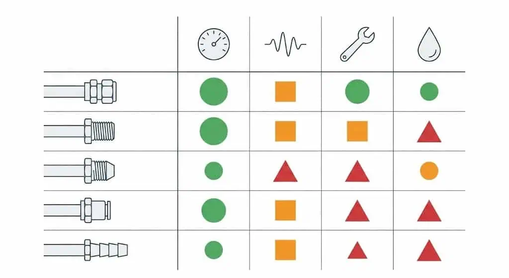
You will encounter several main types of tube fittings in industrial fluid systems: compression, mechanical grip, threaded, cone and thread, push-to-connect, and barbed fittings.
Selecting the right fitting is critical for safety, reliability, and efficient operation. In field work, most “mystery leaks” trace back to one of three issues: the wrong connection type for the duty (pressure/temperature/vibration), a mismatched thread standard, or poor tube/hose end preparation. If you also need an installation procedure and inspection checklist, reference your internal guide on tube fitting installation and the leak-prevention checklist for instrumentation tube fittings.
| Component Category (Example Market Split) | Reported Share (Example Source) |
|---|---|
| Tubes / Pipes | 58.6% (report-specific; definitions vary) |
| Fittings / Connectors / Other | Varies by report scope (use source definitions) |
- Tube fittings create leak-tight seals, which are essential for safety—especially in gas service and in systems with thermal cycling.
- Material choice and fitting type affect pull-out resistance, corrosion risk, and how the joint behaves under vibration. For tubing, specs such as ASTM A269 are widely used in corrosion-resisting and temperature service (confirm grade, finish, and wall thickness with your design basis).
- Following standards (thread standards, material specs, and connection test methods) reduces variability between installers and improves auditability during commissioning and maintenance.
Sunhy’s instrumentation tube fittings are one example of engineered components used for demanding environments. Regardless of brand, the engineering rule is consistent: choose a fitting family that matches the duty (pressure/temperature/chemistry), then control installation variables (tube end prep, insertion depth, tightening method, and verification).
Types of Tube Fittings
Compression Tube Fittings
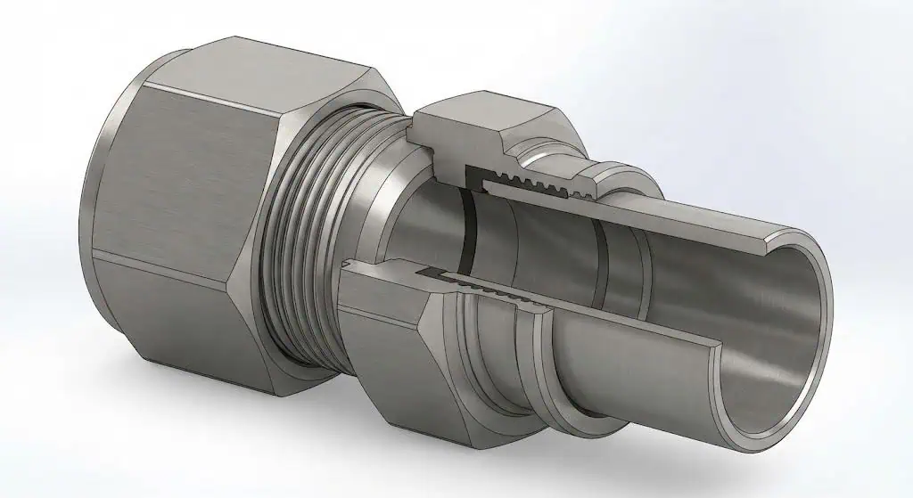
Compression tube fittings create a leak-tight seal by compressing a ferrule onto the tubing.
In instrumentation service, this is typically a single-ferrule or double-ferrule design. What matters in practice is how the ferrule loads the tube: surface finish, wall thickness, and roundness directly affect sealing repeatability. You will find compression fittings in industries like Oil & Gas, Hydrogen, and Semiconductors where vibration control, cleanliness, and rework speed matter. Compression fittings are easy to assemble and disassemble for maintenance—if the tubing is prepared correctly and the tightening method is controlled.
Field case (leak after start-up): A 1/2 in. stainless tube line passed a soap test at low pressure, then leaked after the first thermal cycle. Root cause was shallow insertion (tube not fully seated to the shoulder) combined with a light scratch near the ferrule bite zone. Fix was to cut back to clean tube, deburr, reinsert fully, and tighten using a marked “turn” method. Preventive control: reject scratched tube ends and use witness marks for final pull-up.
Engineering note: Pressure rating is usually limited by the lowest-rated component (often the tubing itself). Treat fittings and tubing as one system and verify tubing specification, wall thickness, and allowable pressure at temperature.
Mechanical Grip Tube Fittings
Mechanical grip tube fittings use a restraint feature to provide extra tube retention and pullout resistance.
In practice, “mechanical grip” may describe designs that add a wedge/collet/grip mechanism or a reinforced sleeve that increases axial restraint beyond friction-only compression. You should consider these fittings when the system sees vibration, operator-induced side load, or repeated pressure cycling—especially in areas where tubing support spacing is limited.
| Engineering Feature (What to Verify) | Compression Fitting (Typical) | Mechanical Grip / Restrained (Typical) |
|---|---|---|
| Primary sealing method | Ferrule compression on tube OD | Ferrule/seal + added restraint element |
| Best for | General instrumentation, serviceability | Higher vibration/side-load risk points |
| Restraint | Moderate to high (design dependent) | High (design dependent) |
| Installation sensitivity | High (tube prep + correct pull-up) | High (tube prep + correct engagement) |
| Common failure mode | Leak from scratches or under/over-tightening | Leak or pullout from incomplete engagement |
Field case (vibration weep): A small-bore impulse line on a reciprocating pump developed a slow weep at the fitting after weeks. Root cause was tubing support spacing too wide, creating alternating bending load at the joint. Fix was adding support clamps within the recommended span and remaking the connection. Preventive control: treat support as part of the joint design, not “afterthought hardware.”
Threaded Tube Fittings
Threaded tube fittings connect components using male and female threads.
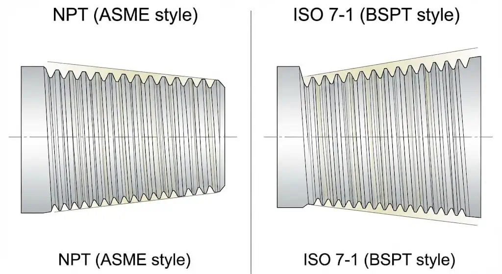
There are two main engineering families: straight (parallel) threads and tapered threads. Straight threads generally do not seal on the threads; they rely on an O-ring, gasket, or metal-to-metal seat in a defined port geometry. Tapered threads can form a seal through thread interference, but sealing performance still depends on thread form, surface finish, engagement length, and (where applicable) sealant selection.
Standard thread types include National Pipe Thread (NPT) defined by ASME B1.20.1, and pressure-tight pipe thread systems defined by ISO 7-1 (commonly associated with BSPT forms). The practical rule: standardize and label thread systems at the facility level to prevent cross-threading and chronic leakage.
Field case (intermittent leak, repeated rework): A maintenance team repeatedly remade a “1/4 in. pipe thread” joint that would not hold pressure. Root cause was mixing thread systems (a tapered male thread forced into a non-matching female port). The joint felt tight but had poor flank contact and micro-leak paths. Fix was confirming thread standard with gauges, then replacing the mating port/fitting to a matched standard.
Cone and Thread Tube Fittings

Cone and thread tube fittings use a coned tube end and a threaded collar to create a high-pressure seal.
You will find these fittings in Oil & Gas, Hydrogen, and other demanding industries where pressure levels can be extreme. Cone and thread fittings require specialized tooling and controlled workmanship (coning quality, thread form, cleanliness, and correct torque). When selected correctly, they provide repeatable performance for high-pressure circuits.
Engineering boundary: Cone and thread systems are commonly used in medium- and high-pressure applications up to 60,000 psig in certain product series (verify your exact size/material series and temperature limits with the manufacturer’s catalog and your design code basis).
Push-to-Connect Tube Fittings
Push-to-connect tube fittings allow you to make quick, tool-free connections.
These are widely used in pneumatic controls and automation where frequent assembly/disassembly is required and operating pressures are typically in the low-MPa range. Engineering controls matter here more than most people expect: tube OD tolerance, roundness, cut squareness, and full insertion are the difference between stable service and nuisance leaks.
- Quick assembly and disassembly saves time during panel build and maintenance.
- Best suited to clean pneumatic service and applications with limited temperature and chemical exposure (confirm seal material compatibility).
- Installation quality is still measurable—use a consistent tube cutter, deburr, and verify full insertion by visual witness lines where possible.
Field case (tube blow-off on start-up): A push-to-connect joint released under pressure because the tube was cut with a saw and left slightly oval with burrs. The collet engaged inconsistently. Fix was to re-cut square with a tube cutter, deburr, and insert to full depth. Preventive control: reject deformed tube ends and establish a “no saw cuts” rule for this fitting family.
Barbed Tube Fittings
Barbed tube fittings use a series of ridges (barbs) to grip flexible tubing.
You will see these in irrigation, agricultural spraying, pneumatic service, and general water transfer where flexible hose is preferred. Barbed fittings are clamp-dependent: the seal is formed by hose material compression, barb geometry, and clamp load. Because of that, the practical pressure limit is highly dependent on hose type, temperature, clamp selection, and whether the service is liquid or gas. Many brass hose barb assemblies are commonly rated around 150 psi at room temperature in general service products, but you should treat that as an example—not a universal rating.
- Used in flexible hose connections
- Applied in irrigation and spraying systems
- Utilized in general water transfer and utility hookups
- Found in some pneumatic systems where specified
- Common in water treatment support systems
- Employed where fast hose serviceability is prioritized
Engineering note: Clamp choice and installation method are part of the joint design. If the duty includes vibration, vacuum, or gas service, verify the hose + barb + clamp combination as an assembly—not as separate parts.
Specialty Tube Fittings
Specialty tube fittings address unique industrial constraints such as space limits, purity requirements, extreme pressure, or frequent routing changes.
In engineering terms, “specialty” usually means one of the following: bulkhead unions, swivel/adjustable elbows, high-purity face-seal connections, instrument manifold adapters, or high-pressure families. Select these when your system constraints cannot be solved by a standard union/elbow/tee without introducing side load, dead volume, or serviceability issues.
- High-purity and low-dead-volume designs for analytical and semiconductor service (verify internal surface and cleaning requirements).
- Swivel and adjustable fittings for alignment control (reduce assembly side load).
- High-pressure families for test rigs and hydrogen compression skids (verify rating basis and temperature limits).
- Bulkhead and panel-mount fittings for enclosures and instrument panels (verify locknut torque and sealing method).
- Application-specific materials for chloride service, H2S cracking risk, or seawater exposure (verify material limits against your corrosion control plan).
In commissioning and maintenance, the “best” fitting is the one that remains tight after the first thermal cycle and vibration exposure, without requiring rework. That outcome depends as much on installation control and tubing support as it does on the fitting geometry.
In summary:
You have many types of tube fittings to choose from, each with its own strengths. Compression and mechanical grip fittings support leak-tight performance in critical systems when installation is controlled. Threaded fittings require strict thread-standard discipline. Cone and thread covers true high-pressure work with specialized tooling. Push-to-connect and barbed fittings serve low-pressure and serviceable hose/pneumatic needs—when their limits are respected and verified as an assembly.
How Tube Fittings Work and Where to Use Them
Compression Fittings: Leak-Tight Seals and Vibration Resistance
Compression fittings create a leak-tight seal by controlled ferrule deformation on the tube OD.
You assemble these tube fittings using a nut, ferrules, and a fitting body. When you tighten the nut, the ferrules load the tube and create sealing stress at defined contact bands. That’s why tube preparation is not cosmetic—it is functional. Many connector standards reference uniform test approaches for metallic tube connections (for example, ISO test-method frameworks used in hydraulic and general applications), which is why consistent installation practice matters.
You often see double ferrule compression tube fittings in hydrogen and semiconductor service because they support clean assembly and repeatable sealing when tube prep and pull-up are controlled. Always validate material compatibility and cleanliness requirements for your specific fluid and purity class.
- Leak-tight sealing under controlled assembly
- Performance depends on tube wall thickness, surface condition, and correct insertion depth
- Suitable for thermal cycling and vibration when tubing is supported and side-load is minimized
Mechanical Grip Fittings: Enhanced Performance in Critical Systems
Mechanical grip fittings focus on retention and stability in critical applications.
You use these industrial tube fittings where you expect vibration, bending load risk, or high consequence of failure. The practical engineering goal is to keep the joint from moving: control support spacing, routing stress, and avoid using the fitting as a structural member.
- Higher retention margin where pullout risk exists
- Useful for high vibration areas and tight routing constraints
- Still sensitive to tube end quality and full engagement
Threaded Fittings: Straight vs. Tapered Threads
Threaded tube fittings require strict control of thread type and sealing method.
You choose between straight and tapered threads based on your port geometry and sealing design. Straight threads typically seal with an O-ring or gasket at a defined face/seat; tapered threads rely on interference and may require sealant depending on the standard and service.
| Type | Sealing Method | Leak Prevention Control | Best for |
|---|---|---|---|
| Straight (Parallel) Threads | O-ring, gasket, or defined seat | Seal condition + surface finish + correct assembly | Ports designed for elastomer/seat sealing |
| Tapered Threads | Thread interference (often with sealant per practice) | Matched standard + engagement length + sealant discipline | Utility connections and specified pipe-thread joints |
You reduce failures by standardizing thread systems (NPT vs ISO/BSP forms), training installers to identify threads with gauges, and documenting the correct sealant policy by service (liquid vs gas, oxygen cleanliness, temperature).
Cone and Thread Fittings: High-Pressure Applications
Cone and thread fittings deliver reliable performance in high-pressure environments.
You use these tube fittings in Oil & Gas, hydrogen, and test systems where pressures can reach up to 60,000 psig for certain catalog series. These fittings require specialized tools for coning/threading and strict cleanliness. If you are in sour service, you should look for materials that meet limits defined in NACE MR0175/ISO 15156 (verify the applicable part and material class for your environment).
| Standard/Certification | Description |
|---|---|
| NACE MR0175/ISO 15156 | Material selection and qualification guidance for H2S cracking resistance in oil & gas environments |
| Pressure Rating | Series- and size-dependent; verify catalog rating basis and temperature limits |
Push-to-Connect and Barbed Fittings: Quick Assembly and Low-Pressure Uses
Push-to-connect and barbed tube fittings target speed and serviceability, primarily in low-pressure systems.
You use push-to-connect fittings in pneumatic controls and automation panels; barbed fittings are common where flexible hose routing is required. The key engineering check is not just “Does it fit?” but “Is this joint validated as an assembly at temperature, pressure, and fluid chemistry?”
- Quick assembly saves time
- Ideal for frequent connections
- Best for low-pressure applications where limits are clearly defined and verified
You can rely on single ferrule compression tube fittings and double ferrule compression tube fittings for more demanding duties, while push-to-connect and barbed options keep things simple for specified low-pressure service.
Choosing the Right Tube Fitting
Material Compatibility and Corrosion Resistance
You must match the fitting material to your tubing and fluid to prevent corrosion and ensure long-lasting performance. Start with the basics: base material family (316/316L, duplex, nickel alloy), chloride exposure, temperature, and whether your system has H2S cracking risk. If you use different materials between tube and fitting, document why and validate galvanic/corrosion risk under actual service conditions. For quick material-grade context and certification expectations, reference Pipe Fitting & Flange Material Grades.
- Material compatibility affects chemical resistance and long-term leak risk.
- Using the same alloy family for tubes and fittings reduces unknowns. If you mix materials, test under real conditions.
- For regulated or high-risk service, document heat code traceability and required MTC level (for example EN 10204 3.1 where specified).
- Corrosion-resistant alloys protect uptime, but selection must align with the actual corrosion mechanism (general corrosion vs SCC vs sulfide cracking).
Tip: In chloride service, “316L” is not a blanket solution. Temperature, chloride concentration, and crevice geometry often control the outcome. If the consequence of leakage is high, treat material selection as an engineering calculation, not a purchasing shortcut.
Pressure and Temperature Ratings
You need to select fittings that meet your system’s pressure and temperature requirements. Pressure ratings are typically based on the tubing, the fitting series, and the connection standard’s qualification tests. Always apply temperature derating per the manufacturer’s published rules and consider your design code margin. If you are using austenitic stainless steels at elevated temperature, be aware that prolonged exposure in the sensitization range can change corrosion behavior depending on grade and environment.
| Temperature (°F) | 316SS | Monel®400 |
|---|---|---|
| 100 | 1.00 | 1.00 |
| 400 | .97 | .79 |
| 800 | .80* | .76 |
| 1000 | .73* | n/a |
*Note: Carbide precipitation (sensitization risk) can occur in certain austenitic stainless steels in the approximate 800–1650°F range depending on time-at-temperature, grade, and environment. Treat this as a materials-engineering check when the duty is hot and corrosive—not as a generic “always happens” rule.

- Check the maximum pressure and surge pressure the system will face (include transient events).
- Confirm the fitting and tubing rating basis at temperature (apply derating, and verify seal material limits where elastomers are used).
- Control vibration and side load—mechanical stress can create leaks even when pressure rating is “adequate on paper.”
Installation and Maintenance Considerations
You should follow best practices for installation and maintenance to keep your system safe and efficient. Most leakage problems are procedural: inconsistent tube cutting/deburring, incomplete insertion, and uncontrolled tightening. Treat installation as a controlled process: define tools, acceptance criteria, and verification steps (leak test, witness marks, visual inspection).
- Store tubing and fittings clean and dry; cap ends to prevent contamination.
- Use correct cutting and deburring tools; reject oval or scratched tube ends.
- Align tubing to the fitting naturally—do not “spring” tubing into place.
- Support tubing to prevent cyclic bending at the fitting.
- Leak test at an appropriate stage (local test before full system pressurization when practical).
- Inspect fittings regularly for weep marks, vibration rub, and clamp integrity.
- Document remake policy (what can be reused, what must be replaced) for your fitting family.
- Use training and a defined installation method (turn method/torque method per manufacturer) for repeatability.
Note: If your site has repeat leakage, audit the installation variables first (tube prep, insertion depth, support, and tightening method). The joint is usually telling you what changed.
Certification and Traceability
You must choose fittings with proper certifications and traceability for regulated industries. The goal is simple: you must be able to prove what material you installed, which heat/lot it came from, and which tests were performed. EN 10204 inspection documents are widely used as part of that evidence trail. If you need a practical reading guide for MTCs, reference How To Interpret a Material Certificate (MTC).
| Category | Required Document | Condition |
|---|---|---|
| II, III, IV | Inspection certificate 3.1 EN 10204 | Certified QA system at material manufacturer |
| II, III, IV | Inspection certificate 3.2 EN 10204 | No certified QA system at material manufacturer |
| I | Test Report 2.2 EN 10204 | N/A |
| N/A | Certificate of compliance 2.1 EN 10204 | For other parts |
- Certifications like ISO 9001 and PED can support a quality management framework, but they do not replace part-level traceability.
- Traceability (heat number/lot control) reduces risk during investigations and repair work.
- For critical service, specify documentation at RFQ stage and verify it at receiving inspection—before parts enter stores.
Tip: If you cannot trace a fitting to its material test results, you cannot defend its use in a regulated investigation. Treat documentation as part of the product.
Benefits of Using the Correct Tube Fittings
Safety and Leak Prevention
Using the right tube fittings keeps your system safe and prevents leaks.
Leak prevention is not only a cost issue; it is a personnel and process hazard issue (chemical exposure, fire risk, contamination, and unplanned shutdowns). The most reliable improvement is to match the fitting family to the duty and then enforce a repeatable installation and verification method.
- You reduce exposure and spill risk by preventing chronic weeps.
- You lower the probability of sudden joint release by controlling side load and retention margin.
- You improve commissioning quality when thread standards and installation steps are standardized.
Tip: If you have repeated leaks at one location, inspect routing/support and verify the connection standard before changing brands or materials.
Operational Efficiency and Cost Savings
Proper tube fittings improve efficiency and reduce rework.
The cost driver in most plants is not the fitting itself; it is technician time, re-test time, and lost production. When you use a fitting family with a controlled installation method and clear acceptance checks, you cut the “rework loop” during commissioning.
- You minimize downtime by reducing re-makes and repeated leak tests.
- You reduce scrap by standardizing tube prep tools and acceptance criteria.
- You simplify maintenance by limiting the number of connection families on site.
| Benefit | How It Helps You |
|---|---|
| Fewer leaks | Less rework and less unplanned maintenance |
| Lower maintenance cost | Fewer remakes and repeated pressure tests |
| Better system stability | More predictable performance under cycling and vibration |
Longevity and System Performance
Choosing the correct fittings increases system life and performance.
Joint longevity is driven by controlled stress: corrosion risk, vibration, thermal cycling, and side load. When you select the right connection type and install it with a repeatable method, you reduce long-term leakage risk and keep performance stable.
- You maintain sealing stress by avoiding tube movement and bending load at the joint.
- You reduce corrosion-driven leakage by matching alloy to environment.
- You improve auditability by specifying certification and traceability.
Note: A well-chosen fitting reduces the probability of a leak, but a well-controlled installation process is what makes that probability repeatable.
You need to choose the right tube fitting for safety, reliability, and performance. Each type—compression, mechanical grip, threaded, cone and thread, push-to-connect, and barbed—serves a specific purpose. Review your system’s needs (fluid, temperature, pressure, vibration, certification), then standardize installation and verification. If you need an auditable training/installation framework, industry resources and structured training can reduce failure rates in commissioning.
| Key Step | Why It Matters |
|---|---|
| Standardize and Inspect | Prevents mix-ups and improves repeatability |
| Select Materials | Controls corrosion and cracking risk |
| Confirm Ratings | Ensures pressure/temperature margin with derating |
| Verify Against a Standard Test Basis | Supports measurable performance expectations |
Always review your system requirements and consult trusted manufacturer manuals and standards before installation, especially where pressure, toxicity, or cleanliness requirements are high.
FAQ
What is the most important factor when choosing tube fittings for your systems?
You should match the fitting family to the duty: pressure, temperature, vibration/side load, and fluid chemistry. Then verify the connection standard (thread type or tube connection family) and define a repeatable installation/inspection method.
- Confirm pressure and temperature with derating rules
- Check material compatibility (including elastomer seals where used)
- Standardize thread types and fitting families across the facility
How do you prevent leaks in fluid systems?
You prevent leaks by controlling selection, installation variables, and verification. In practice, the fastest improvement is to standardize tube preparation tools, require full insertion to the shoulder, use a defined tightening method (turn/torque per manufacturer), and perform a leak test with documented acceptance.
- Use the correct fitting family for vibration and cycling
- Tighten to the specified method (turns/torque) and use witness marks
- Support tubing and remove side load at the joint
Can you reuse tube fittings in your systems?
You can reuse some components, but reusability depends on fitting family and inspection results. As an engineering control, define a remake policy: what can be reused (body/nut), what must be replaced (sealing elements/ferrules where specified), and what inspection criteria reject parts (thread damage, galling, deformation, or bite-zone defects).
- Inspect sealing surfaces, threads, and tube bite zones
- Replace any deformed sealing elements as required by the fitting family
- Do not reuse if your system’s safety margin depends on a perfect seal
Why do different systems require different tube fitting materials?
Different systems fail by different mechanisms: general corrosion, pitting/crevice, stress corrosion cracking, sulfide cracking, or seal degradation. Material selection must match the dominant mechanism at the actual temperature and chemistry, not just the “typical” service label.
- Corrosive fluids need resistant alloys and correct surface condition
- High-temperature systems require derating and sensitization awareness
- H2S environments may require MR0175/ISO 15156 material limits
How do certifications improve safety in your systems?
Certifications and traceability provide evidence that the installed material matches the design and that required tests were performed. For critical service, you should require lot/heat traceability and the correct inspection document level (for example EN 10204 3.1 where specified).
- Traceability supports investigations and repair control
- Inspection documents provide test results tied to the supplied lot
- Receiving inspection is where documentation prevents hidden risk
How do you avoid thread-related leaks when using NPT or ISO/BSP pipe threads?
You avoid thread leaks by confirming the exact thread standard and using the correct sealing method for that standard. Treat “1/4 in. pipe thread” as incomplete information: verify thread form and taper with gauges, ensure correct engagement length, and apply sealant policy only where it is specified and compatible with the fluid service.
- Verify the standard (e.g., NPT per ASME B1.20.1 vs ISO 7-1 forms)
- Do not force non-matching threads; they may feel tight but leak
- Document sealant policy by service (liquid/gas/oxygen cleanliness)


