: insertion, pull-up, and inspection")
To install swagelok type fittings, you need to follow a precise sequence to ensure a safe and leak-free connection. In the field, most “mystery leaks” trace back to one of three root causes: the tube end was not fully seated, the pull-up (nut turns) was not completed correctly, or the tubing OD was damaged where the ferrules seal. Start with verified components (material certs, correct size, no mixed brands), use the correct procedures, and inspect before pressurizing. The typical installation involves these main steps:
- Insert the tubing fully into the fitting until it rests on the shoulder. Finger-tighten the nut.
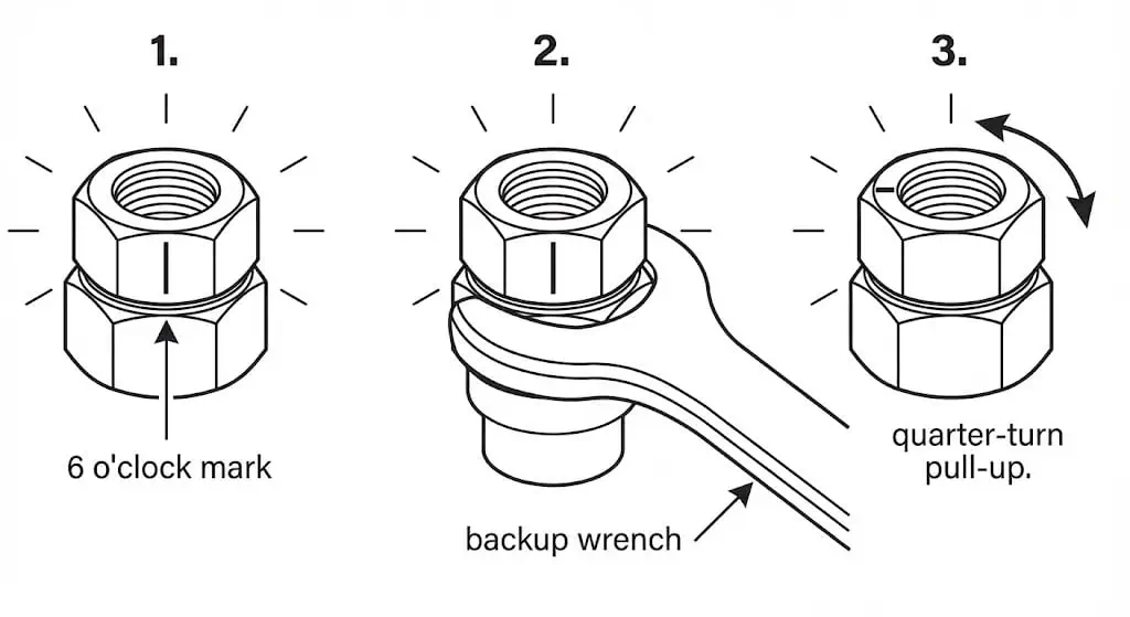
- Mark the nut at the six o’clock position.
- Hold the fitting body steady and tighten the nut one-and-a-quarter turns.
Two practical clarifications that reduce rework: (1) the “1 ¼ turns from finger-tight” method applies to many common tube sizes, but very small sizes may use a different pull-up (follow the manufacturer’s table), and (2) reassembly is not the same as first-time installation—return the nut to the previously pulled-up position rather than adding a fresh 1 ¼ turns.
Following these steps helps you achieve a secure and durable connection.
| What you are doing | Why it matters (engineering reason) | Fast field check |
|---|---|---|
| Tube bottoms on the shoulder | Ferrules swage at the designed location; prevents shallow bite and pullout risk | Mark insertion depth or use a depth marking tool; verify the mark is at the nut after assembly |
| Controlled pull-up (turns from finger-tight) | Sets ferrules and creates a restrained, leak-tight joint without crushing the tube | Mark the nut; confirm final clock position; use the correct gauge where applicable |
| Backup wrench on the body | Prevents body rotation that can twist tubing and introduce stress/fatigue | Body flats remain aligned; tubing line stays square without “wind-up” |
Preparation for Swagelok Type Fittings
Tools and Materials
You need the right tools and materials to ensure a safe and effective installation. From an engineering standpoint, “right tools” means you can control three variables: tube squareness, tube OD surface condition, and nut rotation (pull-up). Using high-quality components—such as Sunhy stainless steel fittings—can be appropriate when you can verify dimensional control, material traceability, and compatibility with your tubing specification.
- Cut & prep: tube cutter (or fine-tooth saw with a squaring guide), internal/external deburring tool, clean wipes.
- Assembly control: two correctly sized wrenches (one backup on the body, one on the nut), marker/paint pen for clocking.
- Verification: calipers for tube OD, visual inspection light, and a manufacturer-approved gap inspection gauge where applicable.
- Cleanliness: solvent compatible with your service (e.g., IPA for general cleaning), and dry, oil-free air or nitrogen for blow-down (especially for instrumentation and gas service).
Swagelok’s tubing data sheet notes repeated successful testing of stainless steel tube fittings with tubing hardness up to 200 HV / 90 HRB, and it also ties allowable tubing pressure calculations to ASME B31.3 methodology. If your tubing is harder than the recommended range or the OD is damaged, ferrules may not seal consistently.
The table below shows common materials and typical compliance references seen in tube fitting installation projects (sour service, offshore, and corrosive environments):
| Material Type | Compliance Standards | Description |
|---|---|---|
| 316/316L SS (tubing common) | ASTM A269/A269M | Common instrumentation tubing specification for corrosion-resisting service; verify OD finish and hardness to support repeatable ferrule sealing. |
| Alloy 2507 | NACE MR0175/ISO 15156 | Often specified for wet H2S (sour) environments; selection must match the service envelope defined by the standard and the component’s wetted exposure conditions. |
| Alloy 625 | NACE MR0175/ISO 15156 | Nickel alloy used for high corrosion resistance; verify the exact product form and qualification route required by project specs. |
| NORSOK Qualified (manufacturer/process) | NORSOK M-650 | Qualification framework used offshore to verify manufacturer competence and process capability for special materials (not a “material grade” by itself). |
Engineering note: “compliance” is not a slogan—ask for EN 10204 3.1/3.2 material test reports where your project requires it, confirm pressure class/ratings are tied to your tubing wall thickness, and verify chemical compatibility with your medium (chlorides, H2S, ammonia, oxygen service, etc.).
Inspecting Tubing and Fittings
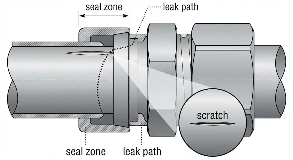
Always inspect tubing and fittings before starting the installation process. This step prevents avoidable leaks and tube damage. In practice, the ferrules seal on the outside diameter of the tube—so cosmetic OD scratches can become functional leak paths.
Follow these steps to ensure safety and reliability:
- Follow the manufacturer’s instructions closely.
- Inspect all parts for dents, thread damage, contamination, and galling (common on stainless threads if abused).
- Confirm the tubing is the correct OD and wall thickness for the fitting, and verify it is not ovalized (out-of-round tubing reduces ferrule contact consistency).
- Cut, deburr, and clean tubes with care; do not “force” a tube past resistance—find the cause (burr, ovality, misalignment).
Tip: Use both your eyes and hands to check for kinks, flattened sections, weld bead defects (if welded tube), and any OD scratches near the seal area. If the OD is damaged, cut back to clean tube rather than hoping the ferrules will “seal it anyway.” A tubing quality checklist is a useful pre-job control to reduce repeat leaks.
Field case (leak on first pressure-up): A nitrogen sample line showed a slow bubble leak after assembly. Root cause was a shallow longitudinal OD scratch exactly where the front ferrule seals. Fix was to cut back 25–40 mm to undamaged tubing, re-prep the end, and remake the fitting; prevention is to protect tube ends during transport and to store cut lengths with caps.
Cleaning and Cutting
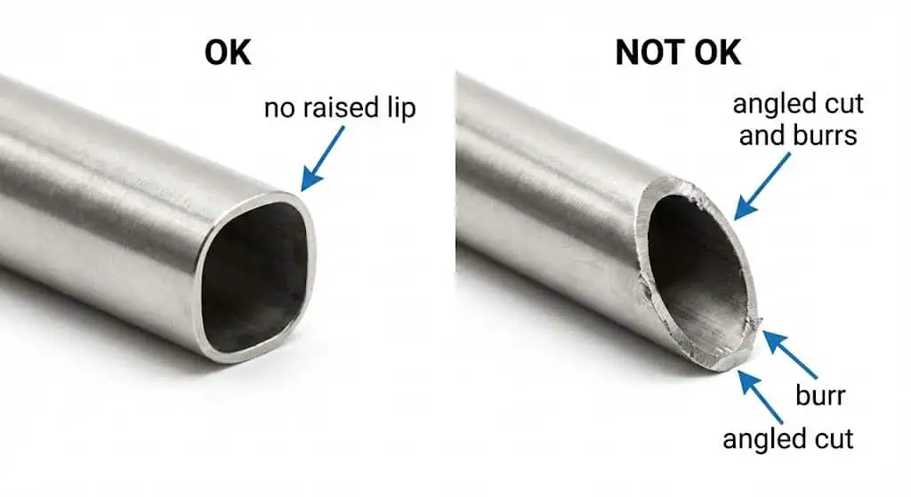
Proper cleaning and cutting prepare the tubing for a secure installation. Use a tube cutter (preferred for repeat squareness) or a fine-tooth saw with a squaring guide. The cut end must be round and square—an angled cut can prevent full bottoming on the shoulder and shift ferrule swaging.
- Deburr inside and outside: remove all raised lips. Internal burrs can shave and carry particles into valves, regulators, and instruments.
- Clean the OD seal zone: wipe with a lint-free cloth; use IPA or an approved solvent; dry with clean air/nitrogen.
- Keep it clean after prep: cap tube ends if the line will not be assembled immediately (especially for gas, oxygen, and analytical sampling).
By following these preparation steps, you set the foundation for a smooth and safe installation.
Tube Fitting Installation Steps
Inserting Tubing
Always insert the tubing fully into the fitting until it reaches the shoulder for a secure connection. This is the foundation of a reliable tube fitting installation.
You need to make sure the tube sits firmly against the fitting’s internal shoulder. This positions the tube correctly so the ferrules engage as designed and you avoid shallow bite, tube pullout, or leak paths.
Follow this sequence for swagelok type fittings:
- Insert the tubing into the pre-assembled fitting body.
- Push the tube in until it stops at the shoulder.
- Hold the tube in place while you bring the nut to finger-tight (do not let the tube back out during this step).
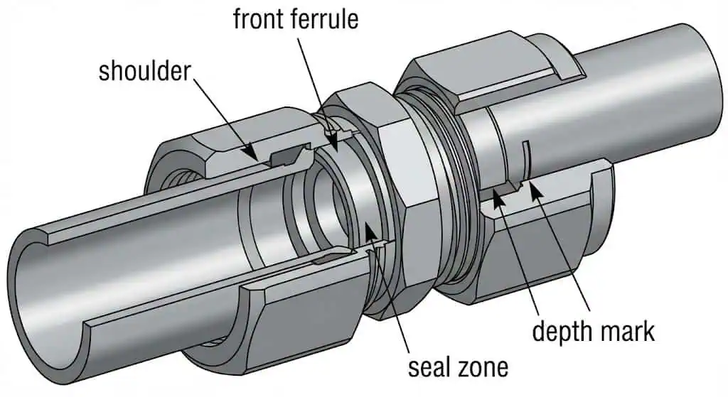
Tip: If you repeatedly find “almost seated” tubes, add an insertion-depth control: mark the tube OD at the back of the nut before tightening, or use a depth marking tool method from the manufacturer’s guide. This is a fast way to catch incomplete insertion on crowded panels.
Field case (intermittent leak under vibration): A compressor instrument line passed a static leak check but leaked after vibration. Root cause was an internal burr that prevented full tube seating; the connection swaged slightly off-position and relaxed under cyclic load. Fix was recut/deburr/clean and remake; prevention is mandatory deburr + visual confirmation of a square end before assembly.
Sunhy’s manufacturing quality can help with repeatability, but correct seating is still the installer’s responsibility—no fitting “self-corrects” an unseated tube.
Tightening the Nut
Tighten the nut by hand first, then use a wrench to complete the turn as specified by the manufacturer. This step sets the ferrules and creates a restrained, leak-tight seal.
Use this method for swagelok type fittings:
- Finger-tighten the nut until you feel firm resistance.
- Mark the nut at the six o’clock position (paint pen/marker).
- Hold the fitting body steady with a backup wrench (prevents tubing twist).
- Use another wrench to tighten the nut the specified number of turns past finger-tight (commonly 1 ¼ turns for many sizes; small sizes may differ—follow the manufacturer’s table).
Engineering note: In high-pressure or high safety-factor systems, some manufacturer guidance calls for an additional “tube will not turn by hand or move axially” verification before final pull-up. This is not about brute force—it is about confirming that the tube is fully seated and engaged before you commit the pull-up.
Avoid two common failure modes: under-tightening (insufficient ferrule set, leak/pullout risk) and over-tightening (tube OD collapse, ferrule damage, thread galling). Both are field-created problems and both are preventable with clocking marks and the correct method.
Field case (galling and “frozen nut”): Stainless nut was run hard without a backup wrench and with repeated start/stop motion on a worn adjustable wrench. Threads galled and seized before proper pull-up was reached. Fix required cutting the assembly. Prevention: correct wrench size, smooth pull-up, backup wrench, and follow any manufacturer lubricant guidance for larger sizes where applicable.
Sunhy’s double ferrule compression technology can provide strong sealing performance when your tubing spec and installation procedure are controlled. The key variable remains correct tube prep and correct pull-up.
Assembly Check
Always check your assembly to confirm the fitting is properly installed and leak-free. Do this before you insulate lines, bundle tubing, or put panels back into service—access is what makes troubleshooting cheap.
Use these checks:
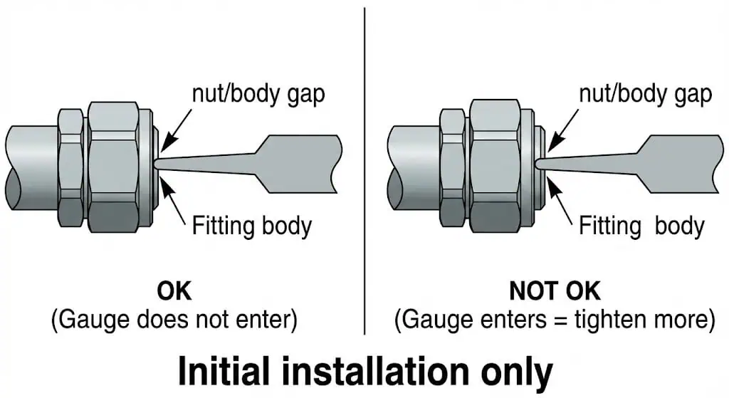
- Use a gap inspection gauge to verify correct pull-up where the manufacturer specifies it (typically for initial installation on applicable sizes/materials).
- Check the gap between the nut and the body hex. The gauge should fit as the manufacturer defines (do not “force” the gauge).
- Visually confirm the nut clocking move (your 6 o’clock mark has advanced the specified amount).
- Confirm the tube has not backed out by checking your insertion mark (if used) is still at the nut location.
Note: Always depressurize the system before adjusting the tightness of a tube fitting connection. Never “snug under pressure.” If you are reassembling a previously made-up fitting, return the nut to the previously pulled-up position using alignment marks; do not apply an additional full initial-installation turn sequence.
After the mechanical checks, perform a leak check appropriate to your service: soap solution for low-pressure air/nitrogen, pressure decay testing for sealed volumes, or helium mass spectrometer methods for high-purity/critical duty. Choose the method that matches the leak tightness requirement and the hazard profile.
By following these steps, you ensure a safe, reliable, and leak-free tube fitting installation every time.
Safety and Best Practices
Personal Protective Equipment
You must always wear the right personal protective equipment (PPE) during installation to protect yourself from injury.
Gloves, safety glasses, and protective clothing protect against sharp tube edges and unexpected releases. Use face protection and barriers when working on pressurized gas systems or where stored energy is significant. Treat every line as pressurized until you have verified isolation and depressurization.
Pressure Testing
You need to perform pressure testing after installation to confirm the system is leak-free and safe.
Pressure testing validates your assembly under controlled conditions before you put the system into service. Hydrostatic testing is often preferred when feasible; pneumatic testing carries higher stored-energy risk and typically requires stricter controls (exclusion zones, incremental pressurization, and additional PPE).
Do not bleed a system by loosening a fitting nut. That practice can cause injury and can damage sealing surfaces. Instead, use the designated venting/bleed points and follow your site procedure.
| Certification | Description |
|---|---|
| ISO 9001:2015 | Quality Management System Registration (verify scope and issuing body) |
| PED 2014/68/EU | Pressure Equipment Directive compliance framework in the EU (design/manufacture/conformity assessment) |
| CE Approvals | European Conformity Declarations (confirm which products/categories the declaration covers) |
These references matter only when they align to your actual duty: pressure, temperature, cyclic loads, vibration, corrosion environment, and regulatory scope. Treat certificates as inputs to your engineering review, not substitutes for it.
Following Manufacturer Guidelines
You should always follow the manufacturer’s guidelines for proper tube fitting installation. When procedures differ between brands, assume the difference is real until proven otherwise.
- Use only flareless, double-ferrule tube fittings as specified for the system duty.
- If your project requires qualification testing for mechanically attached fittings, reference applicable standards such as ASTM F1387 (as required by the owner/specification).
- Make sure only trained personnel perform installation; the highest leak rates I see are almost always training/process issues, not “bad fittings.”
- Prepare and mark tubing as the manufacturer recommends (depth marking, clocking marks, correct pull-up for size/material).
- Use tools approved by the tube fittings manufacturer and avoid rounded or adjustable tools that damage flats and encourage over-torque.
After installation, set up a maintenance/inspection schedule based on your system’s risk: vibration, thermal cycling, corrosive environment, and consequence of leakage. For critical duty, add periodic visual checks for tubing support/clamping and for “line stress” introduced by misalignment.
Tip: A good best practice is “zero avoidable variables”: consistent tube spec, consistent pull-up method, consistent inspection step, and clear rules preventing component mixing.
Avoiding Common Mistakes with Swagelok Type Fittings
Mixing Components
You should never mix components from different manufacturers when installing swagelok type fittings.
From an engineering standpoint, “looks compatible” is not a design standard. Ferrule geometry, hardness, surface finish, and tolerances vary by manufacturer. Mixing parts can produce an assembly that appears tight but seals unpredictably under temperature cycling or vibration.
Mixing components from different manufacturers can increase leak risk and can void warranties and approvals. Independent study results also show that swaging and sealing mechanisms differ across twin-ferrule designs, even when parts look similar.
To avoid this mistake:
- Always use fittings, ferrules, and nuts from the same manufacturer and product family.
- Check packaging and part numbers before installation—especially when multiple brands are stored in the same crib.
- Train your team to recognize and prevent intermixing (a simple two-bin rule by brand reduces errors fast).
Over-tightening or Under-tightening
You must tighten swagelok type fittings according to the manufacturer’s instructions to ensure a proper seal.
Over-tightening can collapse tube OD or damage ferrules. Under-tightening can cause leakage or allow tube movement under load.
To prevent these errors:
- Follow the installation steps exactly and use clocking marks.
- Make sure the tubing rests firmly on the shoulder before tightening (use depth marking if needed).
- Use a gap inspection gauge where specified for initial installation; do not treat it as universal for reassembly.
- Support the tubing so the fitting is not forced to absorb misalignment stress.
Tip: If you need “extra turn” to stop a leak, stop and diagnose. Typical root causes are tube damage, wrong tube OD/wall, incomplete seating, mixed components, or reassembly done like a first-time pull-up.
Reusing Ferrules or Fittings
You should not reuse ferrules as if they were new components.
Ferrules deform during initial pull-up. Reusing ferrules on a new piece of tubing is a common path to leaks because the ferrules are already swaged to a previous OD and position.
Best practices include:
- Do not move “used ferrules” to new tubing. Use new ferrules/nuts as required by the manufacturer and your QA rules.
- Reassembly is acceptable when you are reconnecting the same fitting on the same tubing: mark the tube at the back of the nut and mark a line across nut/body flats before disassembly, then return the nut to the previously pulled-up position.
- Dispose of damaged or galled components; do not chase leaks by repeated over-tightening.
Regular training and self-audits help you avoid these common mistakes. Careful tube handling, controlled pull-up, and an inspection step all contribute to a safe and reliable installation.
By controlling tube prep, seating, pull-up, and inspection, you can install Swagelok type fittings safely and consistently. The practical goal is not “tight,” it is “correctly made up and verifiable.”
| Common FAQ | Quick Answer |
|---|---|
| Are fittings from different brands interchangeable? | No. Do not intermix nuts, ferrules, and bodies across brands. |
| Why is intermixing risky even if it “fits”? | Geometry/tolerances and swaging mechanisms differ; sealing becomes unpredictable. |
| Do I need a cap or a plug? | Caps seal tubing ends; plugs seal ports. Choose by what you are sealing. |
Using the right fittings lowers maintenance costs, prevents avoidable leaks, and improves uptime—mainly by reducing rework and leak-chasing.
FAQ
Can you reuse Swagelok type ferrules or fittings?
Do not reuse ferrules as “new” parts on new tubing.
Ferrules are swaged during first assembly. Reusing them on a different tube often leaks. Reassembly is acceptable when it is the same fitting on the same tube—use alignment marks and return the nut to the prior pulled-up position.
How do you know if the fitting is tight enough?
Use the manufacturer’s verification method for the fitting size/material.
For many fittings, a gap inspection gauge is used on initial installation to confirm sufficient pull-up. Also verify your nut clocking mark and that the tube remained fully seated (depth mark, if used).
What tools do you need for installation?
You need a tube cutter, deburring tool, correctly sized wrenches, and (where specified) a gap inspection gauge.
These tools control squareness, cleanliness, and pull-up—three variables that decide whether you get a stable seal. For a process-ready checklist, see this leak-free connection guide.
Can you mix components from different brands?
No, you should never mix components from different manufacturers.
Even if threads engage, the ferrule swaging and sealing geometry is not standardized across brands. Mixing parts can create latent leaks that appear after thermal cycling or vibration.
What safety gear should you wear during installation?
You should wear gloves, safety glasses, and protective clothing.
Deburring and cutting create sharp edges; pressurized systems store energy. Verify isolation and depressurization before adjustment or disassembly.
Can you disassemble and reassemble a fitting multiple times?
Yes, if it is reassembled correctly.
Before disassembly, mark the tube at the back of the nut and mark a line across nut/body flats. During reassembly, seat the tube/ferrules fully and tighten the nut back to the previously pulled-up position using the marks—do not treat it like a brand-new pull-up.
What tubing specification should I request for instrumentation lines?
Start with the owner’s/project spec, then confirm ASTM grade, wall thickness, and surface condition.
Common stainless instrumentation tubing references include ASTM A269/A269M. For double-ferrule performance, ensure the tubing OD finish is clean and undamaged and that hardness is within the manufacturer’s recommended range.


