Hydrogen induced stress cracking in subsea flanges is prevented by controlling three things together: material and microstructure quality, cathodic protection so hydrogen generation stays within a controlled window, and local tensile stress at known hot-spots such as hub transitions, bores, weld toes, and threaded roots. If one of those controls is weak, a corrosion-resistant subsea flange can still crack under service conditions.
In practice, HISC prevention is not a single material choice or a single CP setting. It is a joined-up integrity strategy that starts with duplex or super duplex material selection, continues through stress-based design and fabrication control, and stays effective only when cathodic protection is monitored at the actual duplex location instead of being assumed safe from system-level settings. For subsea design teams, this is why DNV-RP-F112 and DNV-RP-B401 are often read together rather than in isolation.
For subsea connectors and flange assemblies, sealing integrity still matters alongside cracking resistance. A flange that avoids HISC but cannot maintain sealing under load is not a successful design. That is why material verification, surface condition, flange geometry, and connector qualification should be reviewed together. If you are aligning material, certification, and flange scope across a project package, it also helps to connect this topic with your materials selection workflow and traceability checks such as how to interpret a flange material certificate.
HISC Risks in Subsea Flanges
What Is HISC?
Hydrogen induced stress cracking is a brittle cracking mechanism caused by atomic hydrogen entering a susceptible microstructure while tensile stress or local plastic strain is present. In subsea service, hydrogen is commonly generated on cathodically protected metal surfaces. If hydrogen enters the material at a highly stressed region, cracking can initiate with little visible warning. Unlike general corrosion, HISC is usually a local hot-spot problem rather than a uniform surface-damage problem.
Engineering reality check: good seawater corrosion resistance alone does not prevent HISC. Duplex and super duplex stainless steels may perform well against seawater corrosion but still crack if hydrogen generation is high and local stress at the flange hot-spot is not controlled. This is exactly why stress-based design guidance exists for duplex subsea components under cathodic protection.
Why Subsea Flanges Are Vulnerable
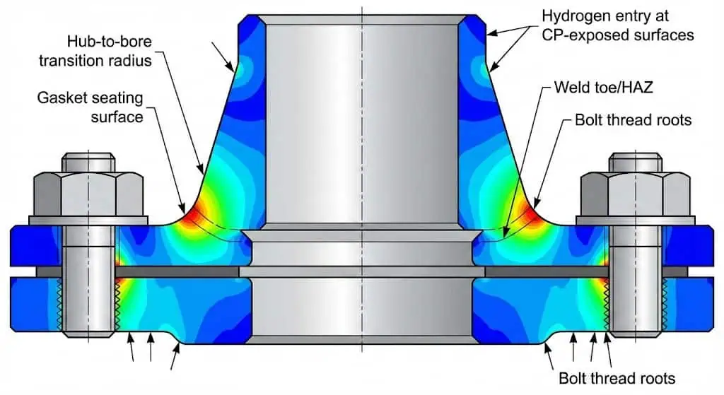
Subsea flanges are vulnerable because they combine cathodic protection exposure, complex geometry, and concentrated tensile stress at exactly the places where hydrogen-assisted cracking likes to start. Hub transitions, bores, weld toes, gasket-seat transitions, and threaded or fastener roots are typical overlap zones where hydrogen generation and peak local stress can occur together.
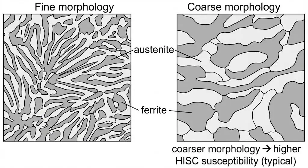
- Duplex and super duplex product forms used in subsea equipment have shown HISC susceptibility in service, and susceptibility is strongly influenced by microstructure quality and austenite morphology in the most highly stressed zones. A useful technical discussion is available in this TWI paper on HISC in duplex subsea components.
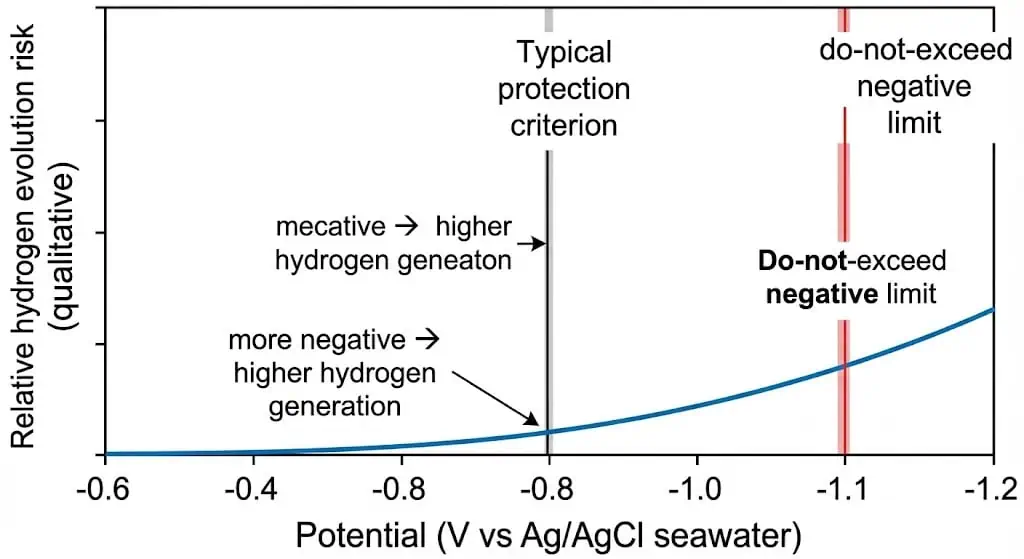
- Cathodic protection can generate atomic hydrogen at the surface. More negative potentials generally increase hydrogen evolution and increase embrittlement risk when the material and stress state are susceptible.
- Bolting, misalignment, installation bending, thermal gradients, and weld profile effects can all increase local tensile stress well above what a nominal pressure-class calculation might suggest.
- Coating damage and local disbonding can create current-density hot-spots, increasing local hydrogen uptake near damaged areas.
A recurring field pattern is not a dramatic external corrosion event, but a crack starting where geometry and restraint are highest. For example, a flange may remain visually acceptable on broad external surfaces while a crack develops at a hub-to-bore transition or near a weld toe where local bending and CP exposure overlap. That is why HISC prevention is less about looking for “overall corrosion” and more about eliminating crack initiation conditions at the local hot-spot.
For subsea connector integrity, sealing qualification and failure-mode awareness remain important because cracks and leaks can become coupled integrity problems once the joint enters service. An example of subsea connector sealing-performance testing can be found here: subsea connector sealing performance testing example.
| Property | Effect on HISC Susceptibility |
|---|---|
| Microstructure (coarse vs. fine) | Coarse morphology and unfavorable phase distribution increase susceptibility. Finer, better-controlled microstructures generally perform better under CP exposure. |
| Austenite spacing | Susceptibility correlates with austenite spacing, but projects must define how it will be measured and how repeatability will be controlled across labs. |
| Product form (forging vs. wrought) | Product form and process route affect HISC performance. Forgings, bar, and wrought forms should not be treated as identical simply because the grade name matches. |
| Local tensile stress / plastic strain | High local stress and local strain accelerate crack initiation and growth. Geometry control and fit-up control matter as much as nominal pressure rating. |
| CP potential and current density | More negative potentials generally increase hydrogen evolution. Monitoring at the duplex hot-spot is critical. |
| Weld / HAZ quality | Unfavorable weld and HAZ microstructure, poor toe profile, or misalignment-induced bending can sharply increase local HISC risk. |
Why Prevention Matters More Than Repair
Preventing HISC in subsea flanges protects safety, uptime, and project economics because repair usually means retrieval, replacement, and investigation after damage has already occurred. HISC is a high-consequence failure mode precisely because it can grow in areas with limited visibility and limited accessibility. A good subsea integrity plan therefore treats HISC as a prevention problem across procurement, design, fabrication, CP operation, and monitoring.
Tip: Treat HISC as a controlled risk chain. If you cannot demonstrate control of microstructure, CP window, and hot-spot stress, you do not yet have a defensible prevention strategy.
Prevention Strategies for Subsea Flanges
Material Selection
Material selection is the first and most effective HISC prevention lever because it defines the baseline resistance before design and operations add more risk. For duplex and super duplex flange components, grade name alone is not enough. Engineers should verify product form, heat-treatment route, traceability, and microstructure acceptance criteria for the actual stressed region rather than relying on generic mill paperwork alone.
Practical procurement control means preventing paper compliance. Require heat and lot traceability, verify solution anneal and heat-treatment records where relevant, and make sure testing represents the most highly stressed location rather than the easiest place to sample. For critical subsea work, audit readiness depends on consistent documentation across MTCs, heat-treatment records, WPS/PQRs, inspection reports, and part markings.
For flange packages in demanding subsea service, it is sensible to connect HISC prevention with your broader high-pressure flange selection logic and traceability requirements. Projects that only specify “super duplex flange” but do not define product-form verification and hot-spot sampling often discover the gap too late.
| Aspect | Description |
|---|---|
| What it applies to | Duplex stainless components installed subsea and exposed to cathodic protection, where HISC initiation must be avoided by limiting stress and strain conservatively. |
| What engineers actually check | Membrane and membrane-plus-bending stress at hot-spots such as hub transitions, bores, weld toes, and other local stress concentrations. |
| Material quality reality | Microstructure matters, and procurement must define what is acceptable and how it will be measured, otherwise “pass” and “fail” may vary between labs. |
| Design implication | Geometry control, transition radii, fit-up, and surface finish are just as important as nominal flange class and material name. |
Note: Audit-ready documentation should allow an independent reviewer to trace material, heat treatment, welding qualification, and inspection results back to the actual flange or connector location.
Design for HISC Resistance
Designing for HISC resistance means controlling local stress concentration, not just checking average stress. In subsea flanges, the critical question is where peak tensile stress overlaps with CP exposure. Rounded transitions, smooth hub-to-bore geometry, controlled weld profile, and realistic fit-up assumptions reduce the probability that a flange hot-spot reaches a dangerous combination of hydrogen and tensile stress.
- Use rounded transitions and avoid sharp corners, abrupt thickness changes, and undercuts.
- Control stress at weld toes and adjacent HAZ through weld profile, fit-up tolerance, and realistic bending cases.
- Specify sampling and acceptance criteria for the actual highest-stress region, not only for coupon-friendly areas.
- Apply stress-based design principles aligned with subsea duplex guidance and document the hot-spot extraction method clearly.
A natural failure pattern seen in subsea reviews is crack initiation at a transition corner after installation misalignment added bending that was not captured in the nominal design load case. In those cases, the corrective action is rarely “increase inspection.” It is usually geometry revision, improved fit-up control, and a revised hot-spot stress evaluation that better reflects the real load path.
Tip: If your design review does not include a hot-spot map showing where hydrogen generation and tensile stress overlap, you are still guessing.
Cathodic Protection Control
Controlling cathodic protection is critical because cathodic protection can generate the hydrogen that drives HISC. The practical aim is to protect the overall subsea structure without driving local duplex or fastener locations into an overly negative potential range where hydrogen evolution becomes excessive. Mixed-material subsea systems are especially sensitive because CP tuned for nearby carbon steel can unintentionally overprotect adjacent duplex hardware.
| Control Issue | Why It Matters for HISC |
|---|---|
| Potential window | Defines the acceptable protection range before hydrogen evolution becomes unnecessarily aggressive. |
| Test point placement | Measurement must be taken where the duplex hot-spot actually sits, not only at convenient structure locations. |
| Coating damage | Damaged coatings can increase local current density and change hydrogen uptake behavior at defects. |
| Mixed-material assemblies | Carbon steel demand can unintentionally push nearby duplex hardware into overprotection. |
Practical control steps usually include defining a measurable potential window using a consistent reference electrode basis, placing measurement points near the duplex location, and monitoring trends rather than relying on isolated readings. A common operations-driven failure pattern is CP output being increased after coating damage on nearby carbon steel, only for the duplex-adjacent region to later see overly negative potentials and crack initiation at an already stressed transition.
When this happens, more inspection does not solve the root problem. The real correction is restoring coating integrity, checking electrical continuity assumptions, and rebalancing the CP system to bring the duplex location back into a controlled window. For teams managing CP operation offshore, the ABS guidance notes on cathodic protection of offshore structures are a useful operating reference.
Alert: If you cannot measure potential at the duplex hot-spot, you cannot claim you are controlling hydrogen generation there.
Coatings and Surface Treatments
Coatings and surface treatments support HISC prevention by limiting hydrogen access and by improving the near-surface stress state. A good coating system reduces local current demand and helps prevent hydrogen-rich hot-spots at defects. Surface compressive treatments, when properly qualified, can also improve resistance by reducing effective tensile stress at the crack initiation layer.
Engineers typically use these controls together rather than individually:
- Coating systems qualified for CP compatibility so they do not simply shift the problem to disbonding or local defect hot-spots.
- Controlled surface-finish requirements at known hot-spots so surface discontinuities do not amplify local stress.
- Surface compressive treatments such as shot peening or other qualified processes where project testing supports their use.
A natural engineering lesson here is that surface condition is not cosmetic in HISC prevention. If a transition region has poor finish, local defects, or coating breakdown, the near-surface layer becomes exactly where hydrogen and tensile stress interact most strongly. That is why coating integrity and surface condition should sit inside the HISC control plan, not in a separate “finish quality” box.
Callout: Coatings only help when they remain intact and are compatible with cathodic protection. A failed coating can increase local hydrogen uptake risk by creating current-density hot-spots at defects.
Welding and Fabrication
Welding and fabrication quality directly affect HISC susceptibility because welds and HAZs often become both stress concentrators and microstructure-sensitive zones. For duplex materials, procedure qualification, heat input control, weld-toe profile, ferrite balance, fit-up, and alignment all influence the final HISC risk of the flange or connector.
Recommended fabrication controls include:
- Qualify WPS and PQR for the actual joint configuration and thickness range rather than borrowing procedures from less constrained geometries.
- Control heat input and interpass conditions so weld and HAZ microstructure remain within accepted bounds.
- Inspect welds and HAZ regions with methods matched to the expected flaw type and location.
- Manage residual stress through fit-up accuracy, controlled sequence, and realistic alignment tolerances.
A common fabrication-driven failure pattern is a weld that passes conventional volumetric inspection but still later cracks near the toe after CP exposure because the real driver was misalignment-induced bending plus poor toe geometry. In that situation, “more NDT” is not enough. The correct response is to tighten fit-up tolerances, improve toe profile control, and reassess hot-spot stress where the weld meets the service load path.
Tip: If the weld or HAZ sits inside a CP-exposed hot-spot, treat procedure qualification and toe-profile control as part of the HISC prevention plan, not as routine QA only.
Inspection and Monitoring
Inspection and monitoring should confirm that the prevention controls remain effective over time. Because subsea access is limited, the best programs combine front-loaded design and fabrication control with trend-based monitoring of CP performance, coating condition, electrical continuity changes, and targeted inspection opportunities when access becomes feasible.
A practical inspection checklist includes:
- Coating condition checks and defined defect-repair criteria
- NDT selection matched to expected cracking location and flaw type
- Review of CP trend data, current output changes, and unexpected potential drift
- Verification that traceability records remain consistent across MTCs, WPS/PQRs, heat-treatment logs, and inspection reports
Note: Monitoring is only useful when it is tied to action thresholds. A drift outside the defined control window should trigger investigation and correction, not just a note for later review.
Implementation Checklist
Step-by-Step Actions
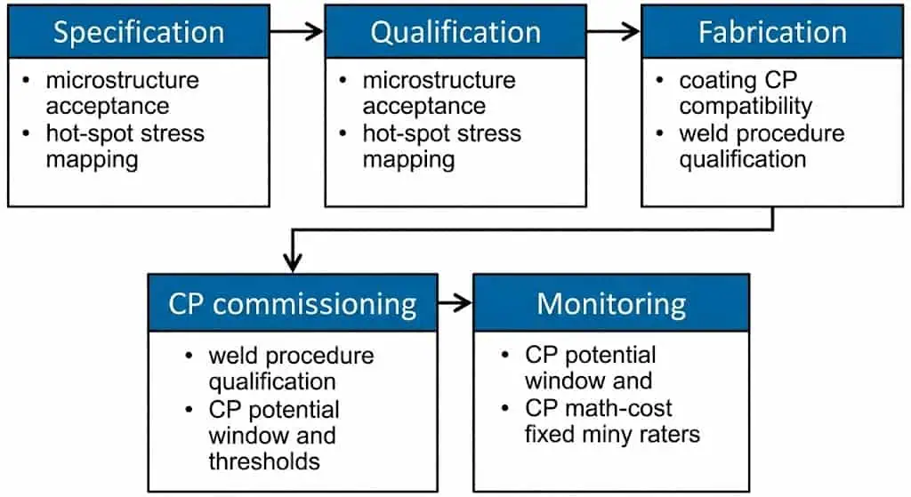
Teams reduce HISC risk in subsea flanges by controlling the full chain: specification → qualification → fabrication → CP operation → monitoring. The steps below work best as an execution checklist rather than as general advice.
- Define service conditions clearly: seawater temperature range, CP philosophy, design life, and inspection accessibility.
- Select duplex or super duplex material with documented traceability and microstructure-quality controls appropriate for CP exposure.
- Align the duplex subsea design with stress-based HISC avoidance logic and document hot-spots and extraction methods clearly.
- Map stress risers at hub transitions, bores, gasket-seat transitions, weld toes, and threaded features.
- Set a measurable CP potential window and test-point plan, including thresholds that trigger investigation.
- Specify coatings and surface treatments for CP compatibility and defect-repair discipline.
- Qualify welding and fabrication procedures for the actual geometry and thickness, including duplex-specific controls where relevant.
- Carry out NDT and dimensional verification at the highest-stress regions, not only at easy-access areas.
- Commission CP with verification at the duplex location and confirm that carbon-steel demand is not unintentionally overprotecting nearby duplex hardware.
- Set monitoring intervals and response actions based on risk, coating condition, CP trends, and connector criticality.
| Control Item | Pass Criteria (Project-defined) | Evidence to File |
|---|---|---|
| Microstructure quality | Acceptance method and sampling plan agreed, with results traceable to part, heat, and zone | MTC, microstructure report, sampling sketch |
| Hot-spot stress mapping | Hot-spots identified, extraction method documented, design limits applied | Calculation note, FEA report if used, assumption log |
| CP potential window | Window defined at the duplex hot-spot and action thresholds documented | Commissioning log, trend plan, electrode method |
| Coating compatibility | Coating system qualified for CP and defect-repair criteria defined | Coating specification, inspection reports, repair log |
| Welding and fabrication control | WPS/PQR qualified, duplex-specific weld and HAZ controls executed | Weld map, ferrite or microstructure checks, NDT records |
Tip: The fastest way to lose control is to treat CP, welding, and flange stress as separate workstreams. HISC lives in the overlap.
Project Documentation
Comprehensive documentation makes the prevention strategy defensible. On subsea projects, documentation proves that the flange you installed is the flange you designed, qualified, and monitored. That includes material traceability, hot-spot stress logic, welding qualification, coating records, and CP commissioning evidence.
| Documentation Type | Purpose | Example |
|---|---|---|
| Material Certificates | Verify chemical, mechanical, and traceability requirements | EN 10204 3.1 MTC plus heat and lot traceability |
| Design Records | Demonstrate stress-based compliance and hot-spot logic | Stress note, FEA report, assumptions register |
| Welding Logs | Track procedures and qualifications | WPS/PQR, weld maps, welder qualifications |
| Coating and Surface Treatment Reports | Confirm CP compatibility and surface-integrity controls | Coating ITP, repair log, peening qualification where used |
| CP Commissioning and Monitoring | Prove the operating window was defined and monitored | Potential logs, current records, test-point layout |
| Inspection Checklists | Ensure repeatable monitoring tied to action thresholds | NDT results, dimensional checks, as-built deviation register |
Note: Audit-ready documentation is how projects avoid “unknown unknowns” during retrieval, failure analysis, or regulatory review.
Common Pitfalls to Avoid
Material Selection Errors
Most material selection errors are verification gaps rather than wrong grade labels. Common mistakes include accepting duplex or super duplex parts without defining microstructure acceptance at the actual hot-spot, relying on generic certificates without zone traceability, and ignoring product-form differences between forgings, bar, and wrought pipe products.
- Define microstructure acceptance and sampling where the real hot-spot sits.
- Require heat and lot traceability plus consistent cross-reference across MTCs, part markings, and inspection records.
- Confirm the material is suitable for subsea CP exposure, not just for seawater corrosion resistance.
- Document as-built deviations together with their stress and CP implications, not only their dimensional acceptance.
Engineering takeaway: If your acceptance criteria do not control microstructure and hot-spot verification, the real gap may only appear in service, when correction is most expensive.
Cathodic Overprotection
Overprotection is usually a system behavior, not an isolated local mistake. It often appears when CP is tuned for nearby carbon steel demands and unintentionally drives adjacent duplex or fastener locations to a more negative potential range. That increases hydrogen evolution and raises HISC likelihood at already stressed hot-spots.
| Best Practice | Explanation |
|---|---|
| Reference electrode consistency | Use a consistent electrode basis and document how offshore readings are interpreted. |
| Test point placement at duplex hot-spots | Measure where the risk actually lives, not only at convenient structure positions. |
| Action thresholds | Define what level of potential drift triggers investigation and correction. |
| Coating repair discipline | Coating damage can increase current demand and alter local hydrogen exposure. |
| Mixed-material awareness | Duplex hardware can become collateral exposure under CP designed mainly for carbon steel. |
| Documentation | Commissioning and trend logs are essential; without them, root-cause review becomes guesswork. |
Teams should treat CP settings as a controlled operating envelope, not a set-and-forget configuration.
Inadequate Inspection
Inadequate inspection usually means the team is checking what is easy to inspect, not what is critical to the HISC mechanism. Effective inspection plans focus on hot-spots, coating-condition changes, CP trends, and targeted NDT where it can actually reduce uncertainty.
| Aspect | Description |
|---|---|
| Hot-spot targeting | Inspection plans should align to hub transitions, weld toes, bores, threads, and other defined hot-spots. |
| Method selection | Use methods that fit the likely flaw type and the geometry of the critical location. |
| Trend-based monitoring | Use CP drift and coating-condition changes as leading indicators that trigger focused inspection. |
| Feedback loop | Recurring indications usually signal a control gap, not just bad luck, and should feed back into design and QA. |
Comprehensive inspection is not “more checks.” It is checks that reduce uncertainty at the hot-spot and confirm that the prevention controls are still effective.
Neglecting Weld-Driven Stress and Profile Control
For subsea hardware, the core fabrication mistake is failing to manage weld-driven stress and profile quality in CP-exposed regions. In duplex systems, the relevant controls are procedure qualification, heat input, phase balance, weld toe profile, fit-up, alignment, and local stress management. Where other steels or fasteners are involved, hardness and strength compatibility with CP become additional control items.
- Verify that welding qualification matches the real restraint and thickness range.
- Control weld toe geometry and alignment so bending-driven hot-spot stress does not escalate after installation.
- Record and disposition as-built deviations that change the stress path at the flange or connector.
Teams that treat welding as a compliance checkbox often miss the real driver: weld profile, alignment, CP exposure, and local hot-spot stress acting together.
Teams prevent HISC in subsea flanges by applying an auditable, connected approach across materials, stress-based design, CP control, fabrication quality, and integrity monitoring. The payoff is not just fewer cracks. It is fewer unplanned retrievals, less downtime exposure, and stronger confidence in long-life subsea assets.
- Reduced crack initiation risk through hot-spot stress control
- Lower hydrogen exposure risk through controlled CP operation
- Better integrity decisions through traceable documentation
- More predictable lifecycle cost and fewer emergency interventions
Ongoing vigilance and regular review keep these controls effective. In subsea flange systems, HISC prevention is strongest when the project team treats materials, CP, welding, inspection, and documentation as one integrity problem rather than separate disciplines.
Technical Review Basis
Reviewed for: subsea flange integrity, duplex and super duplex material control, cathodic protection interaction, weld hot-spot risk, and HISC prevention planning.
Suggested reviewer title: Subsea Materials / Corrosion / Piping Integrity Engineer
Source basis: stress-based duplex subsea HISC design logic, offshore cathodic protection guidance, flange hot-spot assessment practice, fabrication quality control, and subsea integrity documentation requirements.
Last updated: 2026-03-26
FAQ
What is the most effective way to prevent HISC in subsea flanges?
Start with material and microstructure control, then keep hydrogen generation and hot-spot stress or strain within a controlled window.
In subsea service under cathodic protection, prevention is strongest when you can demonstrate:
- Traceable material certificates plus verified microstructure quality in the hot-spot region
- Hot-spot identification at hub transitions, bores, weld toes, and similar local stress concentrations
- CP potential monitoring at the duplex location so unintended overprotection is not missed
How often should teams inspect subsea flanges for HISC?
Inspection frequency should be risk-based, not calendar-based.
As a practical baseline, teams often combine CP trend monitoring with targeted inspection opportunities during retrieval, intervention, or accessible tie-in work. Increase inspection attention when:
- CP potential drifts beyond the defined window at the duplex location
- Coating damage, disbonding, or electrical continuity changes occur
- Installation misalignment, abnormal loading, or bending-driven stress is identified
Which standards guide HISC prevention in flange design?
DNV-RP-F112 is a key reference for duplex stainless subsea components exposed to cathodic protection.
Subsea CP design is commonly aligned with DNV-RP-B401 and offshore CP guidance. Where dimensional flange conventions are relevant, many projects also reference ASME B16.5 flange requirements.
| Standard | Focus Area |
|---|---|
| DNV-RP-F112 | Stress-based HISC avoidance for duplex subsea components under CP |
| DNV-RP-B401 | Cathodic protection design philosophy and parameters |
| ABS CP Guidance Notes | Operational CP criteria, reference-electrode basis, hydrogen and overprotection considerations |
| ASME B16.5 | Pipe flange pressure-temperature ratings, dimensions, and marking where applicable |
Why is cathodic protection control important for HISC prevention?
Because cathodic protection can generate the hydrogen that drives HISC.
When potentials become overly negative at susceptible steels, hydrogen evolution increases. Practical controls include:
- Monitoring potentials at the duplex hot-spot using a consistent reference-electrode basis
- Adjusting CP output and repairing coatings to reduce local current demand
- Using action thresholds so drift triggers correction rather than delayed review
What documentation supports HISC prevention in projects?
Audit-ready documentation proves control across material, design, fabrication, and CP operation.
Teams should maintain:
- Material certificates linked to heat, lot, and part marking
- Design stress notes and hot-spot mapping records
- Welding logs, including WPS/PQR and weld maps
- Coating and surface-treatment reports with repair logs
- CP commissioning records and monitoring trends
What are practical early warning signs that HISC risk is increasing?
Most early warnings are control deviations rather than visible cracks.
Watch for:
- CP potential trending more negative than the defined window at the duplex location
- Coating damage, disbonding, or repeated repair events near the flange or connector
- Unexpected changes in electrical continuity or CP current demand
- As-built misalignment or unexpected bending loads identified during commissioning
Hydrogen induced stress cracking in subsea flanges is prevented by controlling three things together: material and microstructure quality, cathodic protection so hydrogen generation stays within a controlled window, and local tensile stress at known hot-spots such as hub transitions, bores, weld toes, and threaded roots. If one of those controls is weak, a corrosion-resistant subsea flange can still crack under service conditions.
In practice, HISC prevention is not a single material choice or a single CP setting. It is a joined-up integrity strategy that starts with duplex or super duplex material selection, continues through stress-based design and fabrication control, and stays effective only when cathodic protection is monitored at the actual duplex location instead of being assumed safe from system-level settings. For subsea design teams, this is why DNV-RP-F112 and DNV-RP-B401 are often read together rather than in isolation.
For subsea connectors and flange assemblies, sealing integrity still matters alongside cracking resistance. A flange that avoids HISC but cannot maintain sealing under load is not a successful design. That is why material verification, surface condition, flange geometry, and connector qualification should be reviewed together. If you are aligning material, certification, and flange scope across a project package, it also helps to connect this topic with your materials selection workflow and traceability checks such as how to interpret a flange material certificate.
HISC Risks in Subsea Flanges
What Is HISC?
Hydrogen induced stress cracking is a brittle cracking mechanism caused by atomic hydrogen entering a susceptible microstructure while tensile stress or local plastic strain is present. In subsea service, hydrogen is commonly generated on cathodically protected metal surfaces. If hydrogen enters the material at a highly stressed region, cracking can initiate with little visible warning. Unlike general corrosion, HISC is usually a local hot-spot problem rather than a uniform surface-damage problem.
Engineering reality check: good seawater corrosion resistance alone does not prevent HISC. Duplex and super duplex stainless steels may perform well against seawater corrosion but still crack if hydrogen generation is high and local stress at the flange hot-spot is not controlled. This is exactly why stress-based design guidance exists for duplex subsea components under cathodic protection.
Why Subsea Flanges Are Vulnerable
Subsea flanges are vulnerable because they combine cathodic protection exposure, complex geometry, and concentrated tensile stress at exactly the places where hydrogen-assisted cracking likes to start. Hub transitions, bores, weld toes, gasket-seat transitions, and threaded or fastener roots are typical overlap zones where hydrogen generation and peak local stress can occur together.
- Duplex and super duplex product forms used in subsea equipment have shown HISC susceptibility in service, and susceptibility is strongly influenced by microstructure quality and austenite morphology in the most highly stressed zones. A useful technical discussion is available in this TWI paper on HISC in duplex subsea components.
- Cathodic protection can generate atomic hydrogen at the surface. More negative potentials generally increase hydrogen evolution and increase embrittlement risk when the material and stress state are susceptible.
- Bolting, misalignment, installation bending, thermal gradients, and weld profile effects can all increase local tensile stress well above what a nominal pressure-class calculation might suggest.
- Coating damage and local disbonding can create current-density hot-spots, increasing local hydrogen uptake near damaged areas.
A recurring field pattern is not a dramatic external corrosion event, but a crack starting where geometry and restraint are highest. For example, a flange may remain visually acceptable on broad external surfaces while a crack develops at a hub-to-bore transition or near a weld toe where local bending and CP exposure overlap. That is why HISC prevention is less about looking for “overall corrosion” and more about eliminating crack initiation conditions at the local hot-spot.
For subsea connector integrity, sealing qualification and failure-mode awareness remain important because cracks and leaks can become coupled integrity problems once the joint enters service. An example of subsea connector sealing-performance testing can be found here: subsea connector sealing performance testing example.
| Property | Effect on HISC Susceptibility |
|---|---|
| Microstructure (coarse vs. fine) | Coarse morphology and unfavorable phase distribution increase susceptibility. Finer, better-controlled microstructures generally perform better under CP exposure. |
| Austenite spacing | Susceptibility correlates with austenite spacing, but projects must define how it will be measured and how repeatability will be controlled across labs. |
| Product form (forging vs. wrought) | Product form and process route affect HISC performance. Forgings, bar, and wrought forms should not be treated as identical simply because the grade name matches. |
| Local tensile stress / plastic strain | High local stress and local strain accelerate crack initiation and growth. Geometry control and fit-up control matter as much as nominal pressure rating. |
| CP potential and current density | More negative potentials generally increase hydrogen evolution. Monitoring at the duplex hot-spot is critical. |
| Weld / HAZ quality | Unfavorable weld and HAZ microstructure, poor toe profile, or misalignment-induced bending can sharply increase local HISC risk. |
Why Prevention Matters More Than Repair
Preventing HISC in subsea flanges protects safety, uptime, and project economics because repair usually means retrieval, replacement, and investigation after damage has already occurred. HISC is a high-consequence failure mode precisely because it can grow in areas with limited visibility and limited accessibility. A good subsea integrity plan therefore treats HISC as a prevention problem across procurement, design, fabrication, CP operation, and monitoring.
Tip: Treat HISC as a controlled risk chain. If you cannot demonstrate control of microstructure, CP window, and hot-spot stress, you do not yet have a defensible prevention strategy.
Prevention Strategies for Subsea Flanges
Material Selection
Material selection is the first and most effective HISC prevention lever because it defines the baseline resistance before design and operations add more risk. For duplex and super duplex flange components, grade name alone is not enough. Engineers should verify product form, heat-treatment route, traceability, and microstructure acceptance criteria for the actual stressed region rather than relying on generic mill paperwork alone.
Practical procurement control means preventing paper compliance. Require heat and lot traceability, verify solution anneal and heat-treatment records where relevant, and make sure testing represents the most highly stressed location rather than the easiest place to sample. For critical subsea work, audit readiness depends on consistent documentation across MTCs, heat-treatment records, WPS/PQRs, inspection reports, and part markings.
For flange packages in demanding subsea service, it is sensible to connect HISC prevention with your broader high-pressure flange selection logic and traceability requirements. Projects that only specify “super duplex flange” but do not define product-form verification and hot-spot sampling often discover the gap too late.
| Aspect | Description |
|---|---|
| What it applies to | Duplex stainless components installed subsea and exposed to cathodic protection, where HISC initiation must be avoided by limiting stress and strain conservatively. |
| What engineers actually check | Membrane and membrane-plus-bending stress at hot-spots such as hub transitions, bores, weld toes, and other local stress concentrations. |
| Material quality reality | Microstructure matters, and procurement must define what is acceptable and how it will be measured, otherwise “pass” and “fail” may vary between labs. |
| Design implication | Geometry control, transition radii, fit-up, and surface finish are just as important as nominal flange class and material name. |
Note: Audit-ready documentation should allow an independent reviewer to trace material, heat treatment, welding qualification, and inspection results back to the actual flange or connector location.
Design for HISC Resistance
Designing for HISC resistance means controlling local stress concentration, not just checking average stress. In subsea flanges, the critical question is where peak tensile stress overlaps with CP exposure. Rounded transitions, smooth hub-to-bore geometry, controlled weld profile, and realistic fit-up assumptions reduce the probability that a flange hot-spot reaches a dangerous combination of hydrogen and tensile stress.
- Use rounded transitions and avoid sharp corners, abrupt thickness changes, and undercuts.
- Control stress at weld toes and adjacent HAZ through weld profile, fit-up tolerance, and realistic bending cases.
- Specify sampling and acceptance criteria for the actual highest-stress region, not only for coupon-friendly areas.
- Apply stress-based design principles aligned with subsea duplex guidance and document the hot-spot extraction method clearly.
A natural failure pattern seen in subsea reviews is crack initiation at a transition corner after installation misalignment added bending that was not captured in the nominal design load case. In those cases, the corrective action is rarely “increase inspection.” It is usually geometry revision, improved fit-up control, and a revised hot-spot stress evaluation that better reflects the real load path.
Tip: If your design review does not include a hot-spot map showing where hydrogen generation and tensile stress overlap, you are still guessing.
Cathodic Protection Control
Controlling cathodic protection is critical because cathodic protection can generate the hydrogen that drives HISC. The practical aim is to protect the overall subsea structure without driving local duplex or fastener locations into an overly negative potential range where hydrogen evolution becomes excessive. Mixed-material subsea systems are especially sensitive because CP tuned for nearby carbon steel can unintentionally overprotect adjacent duplex hardware.
| Control Issue | Why It Matters for HISC |
|---|---|
| Potential window | Defines the acceptable protection range before hydrogen evolution becomes unnecessarily aggressive. |
| Test point placement | Measurement must be taken where the duplex hot-spot actually sits, not only at convenient structure locations. |
| Coating damage | Damaged coatings can increase local current density and change hydrogen uptake behavior at defects. |
| Mixed-material assemblies | Carbon steel demand can unintentionally push nearby duplex hardware into overprotection. |
Practical control steps usually include defining a measurable potential window using a consistent reference electrode basis, placing measurement points near the duplex location, and monitoring trends rather than relying on isolated readings. A common operations-driven failure pattern is CP output being increased after coating damage on nearby carbon steel, only for the duplex-adjacent region to later see overly negative potentials and crack initiation at an already stressed transition.
When this happens, more inspection does not solve the root problem. The real correction is restoring coating integrity, checking electrical continuity assumptions, and rebalancing the CP system to bring the duplex location back into a controlled window. For teams managing CP operation offshore, the ABS guidance notes on cathodic protection of offshore structures are a useful operating reference.
Alert: If you cannot measure potential at the duplex hot-spot, you cannot claim you are controlling hydrogen generation there.
Coatings and Surface Treatments
Coatings and surface treatments support HISC prevention by limiting hydrogen access and by improving the near-surface stress state. A good coating system reduces local current demand and helps prevent hydrogen-rich hot-spots at defects. Surface compressive treatments, when properly qualified, can also improve resistance by reducing effective tensile stress at the crack initiation layer.
Engineers typically use these controls together rather than individually:
- Coating systems qualified for CP compatibility so they do not simply shift the problem to disbonding or local defect hot-spots.
- Controlled surface-finish requirements at known hot-spots so surface discontinuities do not amplify local stress.
- Surface compressive treatments such as shot peening or other qualified processes where project testing supports their use.
A natural engineering lesson here is that surface condition is not cosmetic in HISC prevention. If a transition region has poor finish, local defects, or coating breakdown, the near-surface layer becomes exactly where hydrogen and tensile stress interact most strongly. That is why coating integrity and surface condition should sit inside the HISC control plan, not in a separate “finish quality” box.
Callout: Coatings only help when they remain intact and are compatible with cathodic protection. A failed coating can increase local hydrogen uptake risk by creating current-density hot-spots at defects.
Welding and Fabrication
Welding and fabrication quality directly affect HISC susceptibility because welds and HAZs often become both stress concentrators and microstructure-sensitive zones. For duplex materials, procedure qualification, heat input control, weld-toe profile, ferrite balance, fit-up, and alignment all influence the final HISC risk of the flange or connector.
Recommended fabrication controls include:
- Qualify WPS and PQR for the actual joint configuration and thickness range rather than borrowing procedures from less constrained geometries.
- Control heat input and interpass conditions so weld and HAZ microstructure remain within accepted bounds.
- Inspect welds and HAZ regions with methods matched to the expected flaw type and location.
- Manage residual stress through fit-up accuracy, controlled sequence, and realistic alignment tolerances.
A common fabrication-driven failure pattern is a weld that passes conventional volumetric inspection but still later cracks near the toe after CP exposure because the real driver was misalignment-induced bending plus poor toe geometry. In that situation, “more NDT” is not enough. The correct response is to tighten fit-up tolerances, improve toe profile control, and reassess hot-spot stress where the weld meets the service load path.
Tip: If the weld or HAZ sits inside a CP-exposed hot-spot, treat procedure qualification and toe-profile control as part of the HISC prevention plan, not as routine QA only.
Inspection and Monitoring
Inspection and monitoring should confirm that the prevention controls remain effective over time. Because subsea access is limited, the best programs combine front-loaded design and fabrication control with trend-based monitoring of CP performance, coating condition, electrical continuity changes, and targeted inspection opportunities when access becomes feasible.
A practical inspection checklist includes:
- Coating condition checks and defined defect-repair criteria
- NDT selection matched to expected cracking location and flaw type
- Review of CP trend data, current output changes, and unexpected potential drift
- Verification that traceability records remain consistent across MTCs, WPS/PQRs, heat-treatment logs, and inspection reports
Note: Monitoring is only useful when it is tied to action thresholds. A drift outside the defined control window should trigger investigation and correction, not just a note for later review.
Implementation Checklist
Step-by-Step Actions
Teams reduce HISC risk in subsea flanges by controlling the full chain: specification → qualification → fabrication → CP operation → monitoring. The steps below work best as an execution checklist rather than as general advice.
- Define service conditions clearly: seawater temperature range, CP philosophy, design life, and inspection accessibility.
- Select duplex or super duplex material with documented traceability and microstructure-quality controls appropriate for CP exposure.
- Align the duplex subsea design with stress-based HISC avoidance logic and document hot-spots and extraction methods clearly.
- Map stress risers at hub transitions, bores, gasket-seat transitions, weld toes, and threaded features.
- Set a measurable CP potential window and test-point plan, including thresholds that trigger investigation.
- Specify coatings and surface treatments for CP compatibility and defect-repair discipline.
- Qualify welding and fabrication procedures for the actual geometry and thickness, including duplex-specific controls where relevant.
- Carry out NDT and dimensional verification at the highest-stress regions, not only at easy-access areas.
- Commission CP with verification at the duplex location and confirm that carbon-steel demand is not unintentionally overprotecting nearby duplex hardware.
- Set monitoring intervals and response actions based on risk, coating condition, CP trends, and connector criticality.
| Control Item | Pass Criteria (Project-defined) | Evidence to File |
|---|---|---|
| Microstructure quality | Acceptance method and sampling plan agreed, with results traceable to part, heat, and zone | MTC, microstructure report, sampling sketch |
| Hot-spot stress mapping | Hot-spots identified, extraction method documented, design limits applied | Calculation note, FEA report if used, assumption log |
| CP potential window | Window defined at the duplex hot-spot and action thresholds documented | Commissioning log, trend plan, electrode method |
| Coating compatibility | Coating system qualified for CP and defect-repair criteria defined | Coating specification, inspection reports, repair log |
| Welding and fabrication control | WPS/PQR qualified, duplex-specific weld and HAZ controls executed | Weld map, ferrite or microstructure checks, NDT records |
Tip: The fastest way to lose control is to treat CP, welding, and flange stress as separate workstreams. HISC lives in the overlap.
Project Documentation
Comprehensive documentation makes the prevention strategy defensible. On subsea projects, documentation proves that the flange you installed is the flange you designed, qualified, and monitored. That includes material traceability, hot-spot stress logic, welding qualification, coating records, and CP commissioning evidence.
| Documentation Type | Purpose | Example |
|---|---|---|
| Material Certificates | Verify chemical, mechanical, and traceability requirements | EN 10204 3.1 MTC plus heat and lot traceability |
| Design Records | Demonstrate stress-based compliance and hot-spot logic | Stress note, FEA report, assumptions register |
| Welding Logs | Track procedures and qualifications | WPS/PQR, weld maps, welder qualifications |
| Coating and Surface Treatment Reports | Confirm CP compatibility and surface-integrity controls | Coating ITP, repair log, peening qualification where used |
| CP Commissioning and Monitoring | Prove the operating window was defined and monitored | Potential logs, current records, test-point layout |
| Inspection Checklists | Ensure repeatable monitoring tied to action thresholds | NDT results, dimensional checks, as-built deviation register |
Note: Audit-ready documentation is how projects avoid “unknown unknowns” during retrieval, failure analysis, or regulatory review.
Common Pitfalls to Avoid
Material Selection Errors
Most material selection errors are verification gaps rather than wrong grade labels. Common mistakes include accepting duplex or super duplex parts without defining microstructure acceptance at the actual hot-spot, relying on generic certificates without zone traceability, and ignoring product-form differences between forgings, bar, and wrought pipe products.
- Define microstructure acceptance and sampling where the real hot-spot sits.
- Require heat and lot traceability plus consistent cross-reference across MTCs, part markings, and inspection records.
- Confirm the material is suitable for subsea CP exposure, not just for seawater corrosion resistance.
- Document as-built deviations together with their stress and CP implications, not only their dimensional acceptance.
Engineering takeaway: If your acceptance criteria do not control microstructure and hot-spot verification, the real gap may only appear in service, when correction is most expensive.
Cathodic Overprotection
Overprotection is usually a system behavior, not an isolated local mistake. It often appears when CP is tuned for nearby carbon steel demands and unintentionally drives adjacent duplex or fastener locations to a more negative potential range. That increases hydrogen evolution and raises HISC likelihood at already stressed hot-spots.
| Best Practice | Explanation |
|---|---|
| Reference electrode consistency | Use a consistent electrode basis and document how offshore readings are interpreted. |
| Test point placement at duplex hot-spots | Measure where the risk actually lives, not only at convenient structure positions. |
| Action thresholds | Define what level of potential drift triggers investigation and correction. |
| Coating repair discipline | Coating damage can increase current demand and alter local hydrogen exposure. |
| Mixed-material awareness | Duplex hardware can become collateral exposure under CP designed mainly for carbon steel. |
| Documentation | Commissioning and trend logs are essential; without them, root-cause review becomes guesswork. |
Teams should treat CP settings as a controlled operating envelope, not a set-and-forget configuration.
Inadequate Inspection
Inadequate inspection usually means the team is checking what is easy to inspect, not what is critical to the HISC mechanism. Effective inspection plans focus on hot-spots, coating-condition changes, CP trends, and targeted NDT where it can actually reduce uncertainty.
| Aspect | Description |
|---|---|
| Hot-spot targeting | Inspection plans should align to hub transitions, weld toes, bores, threads, and other defined hot-spots. |
| Method selection | Use methods that fit the likely flaw type and the geometry of the critical location. |
| Trend-based monitoring | Use CP drift and coating-condition changes as leading indicators that trigger focused inspection. |
| Feedback loop | Recurring indications usually signal a control gap, not just bad luck, and should feed back into design and QA. |
Comprehensive inspection is not “more checks.” It is checks that reduce uncertainty at the hot-spot and confirm that the prevention controls are still effective.
Neglecting Weld-Driven Stress and Profile Control
For subsea hardware, the core fabrication mistake is failing to manage weld-driven stress and profile quality in CP-exposed regions. In duplex systems, the relevant controls are procedure qualification, heat input, phase balance, weld toe profile, fit-up, alignment, and local stress management. Where other steels or fasteners are involved, hardness and strength compatibility with CP become additional control items.
- Verify that welding qualification matches the real restraint and thickness range.
- Control weld toe geometry and alignment so bending-driven hot-spot stress does not escalate after installation.
- Record and disposition as-built deviations that change the stress path at the flange or connector.
Teams that treat welding as a compliance checkbox often miss the real driver: weld profile, alignment, CP exposure, and local hot-spot stress acting together.
Teams prevent HISC in subsea flanges by applying an auditable, connected approach across materials, stress-based design, CP control, fabrication quality, and integrity monitoring. The payoff is not just fewer cracks. It is fewer unplanned retrievals, less downtime exposure, and stronger confidence in long-life subsea assets.
- Reduced crack initiation risk through hot-spot stress control
- Lower hydrogen exposure risk through controlled CP operation
- Better integrity decisions through traceable documentation
- More predictable lifecycle cost and fewer emergency interventions
Ongoing vigilance and regular review keep these controls effective. In subsea flange systems, HISC prevention is strongest when the project team treats materials, CP, welding, inspection, and documentation as one integrity problem rather than separate disciplines.
Technical Review Basis
Reviewed for: subsea flange integrity, duplex and super duplex material control, cathodic protection interaction, weld hot-spot risk, and HISC prevention planning.
Suggested reviewer title: Subsea Materials / Corrosion / Piping Integrity Engineer
Source basis: stress-based duplex subsea HISC design logic, offshore cathodic protection guidance, flange hot-spot assessment practice, fabrication quality control, and subsea integrity documentation requirements.
Last updated: 2026-03-26
FAQ
What is the most effective way to prevent HISC in subsea flanges?
Start with material and microstructure control, then keep hydrogen generation and hot-spot stress or strain within a controlled window.
In subsea service under cathodic protection, prevention is strongest when you can demonstrate:
- Traceable material certificates plus verified microstructure quality in the hot-spot region
- Hot-spot identification at hub transitions, bores, weld toes, and similar local stress concentrations
- CP potential monitoring at the duplex location so unintended overprotection is not missed
How often should teams inspect subsea flanges for HISC?
Inspection frequency should be risk-based, not calendar-based.
As a practical baseline, teams often combine CP trend monitoring with targeted inspection opportunities during retrieval, intervention, or accessible tie-in work. Increase inspection attention when:
- CP potential drifts beyond the defined window at the duplex location
- Coating damage, disbonding, or electrical continuity changes occur
- Installation misalignment, abnormal loading, or bending-driven stress is identified
Which standards guide HISC prevention in flange design?
DNV-RP-F112 is a key reference for duplex stainless subsea components exposed to cathodic protection.
Subsea CP design is commonly aligned with DNV-RP-B401 and offshore CP guidance. Where dimensional flange conventions are relevant, many projects also reference ASME B16.5 flange requirements.
| Standard | Focus Area |
|---|---|
| DNV-RP-F112 | Stress-based HISC avoidance for duplex subsea components under CP |
| DNV-RP-B401 | Cathodic protection design philosophy and parameters |
| ABS CP Guidance Notes | Operational CP criteria, reference-electrode basis, hydrogen and overprotection considerations |
| ASME B16.5 | Pipe flange pressure-temperature ratings, dimensions, and marking where applicable |
Why is cathodic protection control important for HISC prevention?
Because cathodic protection can generate the hydrogen that drives HISC.
When potentials become overly negative at susceptible steels, hydrogen evolution increases. Practical controls include:
- Monitoring potentials at the duplex hot-spot using a consistent reference-electrode basis
- Adjusting CP output and repairing coatings to reduce local current demand
- Using action thresholds so drift triggers correction rather than delayed review
What documentation supports HISC prevention in projects?
Audit-ready documentation proves control across material, design, fabrication, and CP operation.
Teams should maintain:
- Material certificates linked to heat, lot, and part marking
- Design stress notes and hot-spot mapping records
- Welding logs, including WPS/PQR and weld maps
- Coating and surface-treatment reports with repair logs
- CP commissioning records and monitoring trends
What are practical early warning signs that HISC risk is increasing?
Most early warnings are control deviations rather than visible cracks.
Watch for:
- CP potential trending more negative than the defined window at the duplex location
- Coating damage, disbonding, or repeated repair events near the flange or connector
- Unexpected changes in electrical continuity or CP current demand
- As-built misalignment or unexpected bending loads identified during commissioning