")
Selecting and installing the right pneumatic fittings in 2025 requires careful attention to quality, compatibility, and application needs. In real plants, “quality” shows up as measurable controls: correct thread form, predictable torque behavior, stable tube grip, and seal materials that match your media and temperature range. Align your approach with recognized pneumatic safety and design guidance (for example, ISO 4414) and compressed air cleanliness classes (ISO 8573-1) so your fittings don’t become the weak link. If you’re specifying stainless steel fittings, treat “stainless” as a family: choose grade + seal type based on corrosion mode, washdown chemicals, and chloride exposure rather than assuming any stainless will work.
Two practical data points that tend to surprise new owners:
- Leaks are often the largest “hidden load” in compressed air. Poorly maintained systems can lose on the order of 20%–30% of air capacity to leakage; a well-maintained target is typically under 10% (U.S. DOE leak fact sheet).
- Many “mystery leaks” trace back to mismatch in standards (NPT vs BSPT/BSPP vs metric) or to tube OD tolerance/cut quality. Once you lock those down with gauges and documented specs, troubleshooting time drops sharply.
Use this guide to make informed choices for both new pneumatic projects and system upgrades, with selection logic, installation checks, and leak-finding steps you can execute on the shop floor.
Understanding Pneumatic Fittings
What Are Pneumatic Fittings
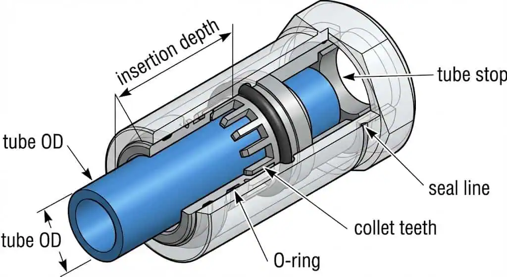
Pneumatic fittings connect and control the flow of air in a pneumatic system. You use these components to join tubes, hoses, manifolds, valves, cylinders, and instruments while managing three failure modes: leakage, pull-out/blow-off, and contamination ingress. A fitting is usually specified by (1) tube size (often OD), (2) port thread type, (3) seal design (O-ring, gasket, metal-to-metal, thread sealant), and (4) body/seal material compatibility.
Here is a quick overview of common fitting types and their uses (for naming conventions and typical forms, see major pneumatic catalogs such as SMC KQ2 One-touch fittings):
| Type of Fitting | Function | Applications |
|---|---|---|
| Straight | Connects two sections of tube/hose in a straight line | Extending tube lines, connecting to actuators, repairing a damaged run |
| Elbow | Directs airflow around obstacles | Turns in air paths, routing in tight panels, avoiding kinked tubing |
| Tee (T) | Divides or combines airflow | Feeding two branches, adding a gauge/regulator takeoff point |
| Union | Joins two tubes and allows easier service | Maintenance access, modular subassemblies |
| Reducer | Transitions between tube sizes | Local flow/space constraints, instrument takeoffs |
| Bulkhead | Pass-through connection across a panel/wall | Control cabinets, machine guarding, clean routing |
| Y fitting | Splits flow with less turbulence than a hard tee | Lower pressure drop splits, smoother routing |
| Swivel/rotary | Allows rotation to reduce tube twist | Robot EOAT, moving cylinders, vibration-prone runs |
Many pneumatic fittings use elastomer seals (often NBR or FKM) to create a leak-resistant connection; the seal selection is frequently what limits temperature and chemical compatibility more than the metal body. Push-in connectors are standardized as a product family in ISO 14743. For threads, do not guess: NPT is defined by ASME B1.20.1; BSPT/BSPP commonly align with ISO 7-1 and ISO 228-1. “Close enough” threads are a repeat leak generator.

Why Proper Selection Matters
Choosing the right pneumatic fittings ensures reliable performance and safety in your pneumatic system. The wrong fitting shows up as pressure instability, higher compressor run time, nuisance cylinder faults, and avoidable maintenance. Selection is not only about “does it connect” but about documented compatibility: thread standard, tube OD tolerance, and the seal material’s limits.
Match the fitting type to your application. For example:
- Push-to-connect (push-in) fittings are built for fast assembly and service access, but they depend heavily on tube cut quality and OD tolerance.
- Threaded fittings provide a robust interface when you control thread standard and sealing method (tapered threads usually require a sealant appropriate for your media).
- Compression fittings deliver repeatable, high-integrity connections when installed per the manufacturer’s make-up method (common in instrumentation and panels).
- Barbed fittings suit soft tubing and light-duty service when you can clamp correctly and prevent pull-off.
- Quick-disconnect couplings support tool changes and maintenance, and are standardized by families such as ISO 6150.
Field example (standards mismatch): A packaging line had recurring leaks at a “1/4 inch” port. The root cause was mixed NPT male into a BSPP female manifold. It threaded in “far enough” to pass a quick soap test, but it loosened under thermal cycling and vibration. Fix: verify thread with gauges, standardize ports (or use the correct adapter), and document thread type on the BOM and drawing. Reference points: ASME B1.20.1 (NPT), ISO 7-1 (BSPT), ISO 228-1 (BSPP).
Tip: Always check compatibility of threads, tube OD tolerance, and seal material with the tubing and operating conditions of your pneumatic system. If the air quality is poor (water/oil/particles), address filtration/drying first—seal life depends on it (ISO 8573-1).
Types of Pneumatic Fittings
You need to understand the main types of pneumatic fittings to choose the right solution for your system. Each type offers unique benefits and works best in specific situations. The “best” fitting is the one that matches service conditions (pressure, temperature, vibration, chemical exposure), and can be installed consistently by the people and tools you actually have on site.
Push-to-Connect
Push-to-connect fittings provide the fastest and easiest installation. You push the tubing into the fitting until it bottoms out; an internal collet grips the tube and an elastomer seal controls leakage. This family is covered by ISO 14743. In practice, performance depends on tube OD tolerance, ovality, surface finish, and a square, burr-free cut.
- Tool-free assembly saves time and reduces rework when lines are serviced often.
- Reusable in many cases, but only if the tube end is re-cut cleanly and the fitting shows no collet/seal damage.
- Best in applications where you can control tube preparation and prevent side-loads; add supports or bulkheads to avoid bending the tube right at the fitting.
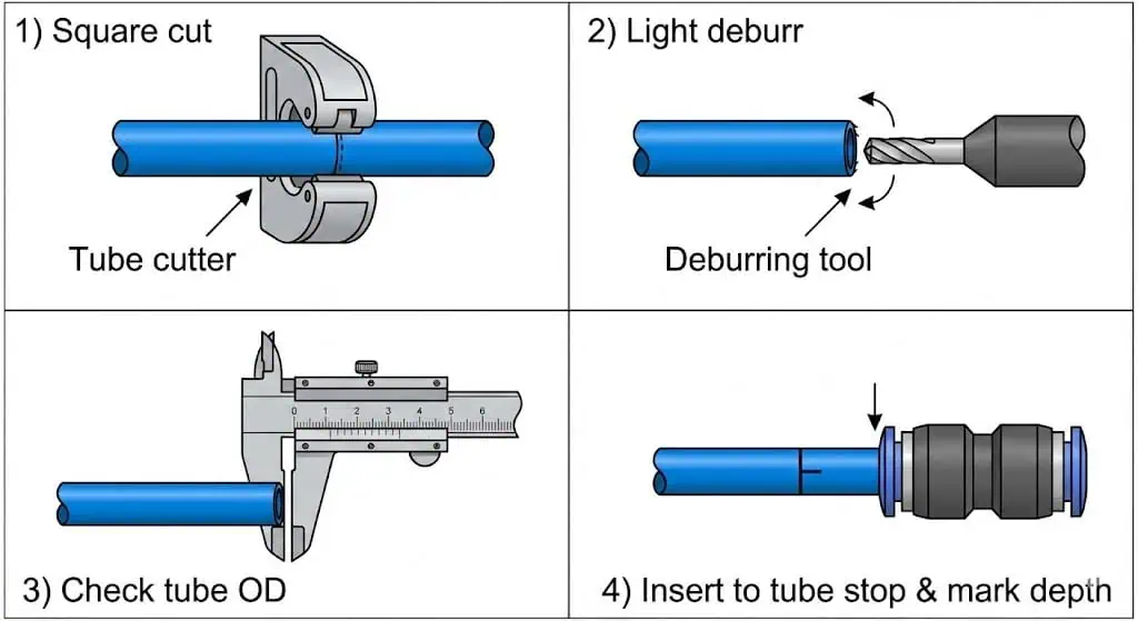
Field example (tube prep): A pick-and-place cell had intermittent cylinder “slow extend” alarms. No obvious leak noise. The issue was micro-leakage at multiple push-in fittings caused by angled tube cuts and minor scratches on the tube OD from a utility knife. Fix: use a proper tube cutter, deburr lightly, blow out chips, mark insertion depth, and re-cut every tube end that has been removed. After rework, pressure stabilized and cycle time variation disappeared.
Tip: If you must route tight, avoid forcing a tube bend immediately at the fitting. Use an elbow fitting or add a short straight “relief” section so the seal line isn’t side-loaded.
Compression
Compression fittings deliver a strong, pressure-resistant seal. You tighten a nut to drive a ferrule (or set of ferrules) onto the tube, creating a repeatable seal and tube grip. This style is common in panels and instrumentation because it tolerates vibration well when assembled correctly. The critical control is make-up method: follow the manufacturer’s “turns past finger-tight” or gauging approach rather than relying on feel.
- Durable and reliable where you want a mechanically stable joint.
- Strong choice for long-term installs in control cabinets, test stands, and instrumentation.
- Requires correct tube material/hardness and careful assembly; reusing ferrules incorrectly is a known failure mode.
Evidence point: Most reputable compression systems publish an explicit assembly method (example: “mark nut position, then tighten X turns past finger-tight”), because torque alone varies with lubrication and thread condition.
| Fitting Type | Key Features | Suitability |
|---|---|---|
| Push-to-Connect | Tool-free, service-friendly, sensitive to tube prep | Quick assembly/disassembly and frequent changes |
| Compression | Mechanically stable, repeatable when assembled correctly | Panels, instrumentation, long-term installations |
Barbed
Barbed fittings create a secure seal with soft tubing. You push the tubing over the barb; retention depends on tube material, wall thickness, temperature, and clamp method. Barbed joints can work well in low-pressure service, but do not treat them as “set and forget” if the line sees heat, vibration, or pull loads.
- Stronger pull-off resistance requires the right tube + proper clamping.
- Lower cost and simple hardware; good for soft tubing and quick prototypes.
- Use clamps where appropriate; document clamp type and torque if the joint is safety-critical.
Field example (pull-off): A maintenance team replaced a push-in with a barb “to simplify.” Under vibration, the soft tube walked off the barb over two shifts and dumped air, stopping the line. Fix: restore the correct fitting type or redesign with proper hose barb + clamp + strain relief, and eliminate tensile load at the joint.
Threaded
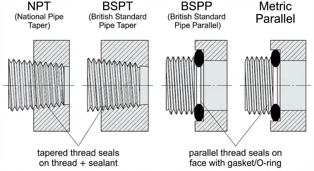
Threaded fittings offer a strong, leak-resistant connection when the thread standard and sealing method match. The most common root causes of threaded leaks are (1) mixed standards and (2) wrong sealing method for the thread type. NPT is a tapered thread system defined by ASME B1.20.1 and typically relies on thread deformation plus an appropriate sealant. BSPP threads (ISO 228-1) are parallel and usually seal with a gasket/O-ring at a face or shoulder, not on the threads.
- Suitable for higher-pressure service when correctly specified and assembled.
- Often used where fittings must resist vibration and mechanical handling.
- Used for connecting pneumatic elbow fittings, pneumatic t fittings, and pneumatic straight fittings—provided the port threads are standardized and documented.
Quick-Disconnect
Quick-disconnect fittings let you connect or disconnect lines instantly. Use them when you need to change tools or fixtures without draining the whole system. In addition to leakage, pay attention to flow restriction and contamination control (dust caps matter on shop floors). Product families and interchangeability are addressed by standards such as ISO 6150.
- Fast tool changes and safer maintenance routines.
- Reliable sealing for frequent connect/disconnect cycles when kept clean.
- Common in assembly lines, test stations, and maintenance connections.
Note: If quick-disconnects are used in dusty or washdown areas, specify protective caps/plugs and define a cleaning step before reconnection—contamination is a leading cause of nuisance leaks and sticking.
You will often combine different types of pneumatic fittings, such as pneumatic elbow fittings and pneumatic t fittings, to build complex systems. Understanding the types of pneumatic fittings helps you select the best fittings for your needs without creating a maintenance trap.
Pneumatic Fitting Selection Guide
Assessing Application Needs
You must evaluate your application needs before choosing pneumatic fittings. This step prevents two expensive mistakes: underspecifying (leaks, pull-outs, failures) and overspecifying (unnecessary cost and lead time). Document these inputs on the job traveler or BOM so the “why” isn’t lost after a shift change:
- Application environment (indoor/outdoor, washdown chemicals, salt air, UV exposure, dust)
- Pneumatic tubing type and material (OD tolerance, hardness, bend radius)
- Required flow rate and allowable pressure drop (especially for fast cylinders)
- Pressure requirements (normal, peak, and any pressure spikes)
- Fitting size and dimensions (clearances, wrench access, service space)
- Special features (quick-disconnect, swivel, bulkhead, locking collet)
- Compliance requirements (food/pharma hygiene, cleanroom, PED/ATEX documentation when applicable)
- Static or swivel fitting requirements and vibration exposure
Evidence point (leak economics): If you are not measuring leak rate, you are guessing. A common benchmark is that well-maintained systems keep leakage under ~10%, while poorly maintained systems can lose ~20%–30% of compressor output (U.S. DOE). Fitting selection and installation quality directly influences that leakage.
Tip: Always match the fitting to your tube spec and your environment. If you do not have a tube datasheet with OD tolerance, treat the application as high risk and standardize the tubing first.
Material Selection for Performance
Selecting the right material for pneumatic fittings impacts durability and safety. Separate “body material” from “seal material.” A stainless body can still leak or crack if the seal is wrong or the thread is mismatched. Use the table below as a practical starting point, then confirm with the supplier’s datasheet for your exact series.
| Material | Key Properties | Applications |
|---|---|---|
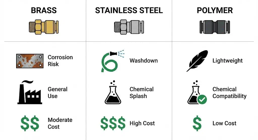
| Brass | Good corrosion resistance, strong, machinable; watch for ammonia/amine exposure in some brasses (typical engineering caution) | General industrial compressed air, indoor automation, many dry-air services |
| Stainless Steel | High corrosion resistance depends on grade and environment; good choice for washdown and chemical exposure when correctly specified (see stainless selection guidance such as Nickel Institute design guidelines) | Food/pharma washdown, chemical processing, marine/near-coastal, corrosive atmospheres |
| Fluoropolymer | Excellent chemical resistance; temperature limit usually driven by seal design and tube material | Semiconductor, analytical instruments, aggressive chemicals (confirm permeation limits) |
| Polyurethane | Flexible, abrasion resistant; check temperature and oil compatibility | Automation, automotive, packaging, moving tool lines |
| Nylon | Lightweight, strong; can be sensitive to moisture/temperature depending on grade | Material handling, textile, general pneumatics |
| Polyethylene | Flexible, chemical resistant, low cost; confirm pressure rating for your wall thickness | Low/medium pressure air distribution to end devices |
Stainless steel fittings are often specified to reduce corrosion risk and simplify washdown, but “stainless” is not a universal pass. For chloride-rich environments, grade selection matters (pitting/crevice corrosion behavior varies by alloy family). If you are evaluating Sunhy’s stainless steel fittings (or any supplier), request the exact material grade, seal compound, and pressure/temperature rating sheet, and verify whether you need PED documentation for pressure equipment in the EU (PED overview).
Note: Seal material is often the hidden limit. For example, NBR and FKM have different temperature and chemical resistance ranges; use published elastomer guidance (e.g., Parker O-ring handbook) and confirm with the fitting series datasheet.
Sizing and Compatibility
Proper sizing and compatibility ensure safe, efficient pneumatic fitting connections. Incorrect sizing causes leaks, pull-outs, and unstable cylinder speed. “Close” is not correct—tube OD tolerance and insertion depth are part of the spec.
- Select tubing size first based on flow, response time, and allowable pressure drop.
- Choose fittings that match the tubing’s outer diameter (OD) and the tubing standard/series you are using.
- Consider the inner diameter (ID) of the tubing, as it affects airflow and pressure drop.
- Ensure compatibility between tubing and fittings to prevent leaks and maintain system safety.
- Double-check that fittings match the port thread type (NPT vs BSPT/BSPP vs metric) and any sealing face requirement.
Field example (OD tolerance): A retrofitted machine used “8 mm” tubing from an unknown source. OD variation and ovality caused push-in fitting micro-leaks that only appeared after the tube warmed up. Fix: standardize tubing to a documented spec, re-cut ends, and replace any fittings with damaged collets/seals. The fast check is simple: caliper several tubes (multiple orientations) and compare to the supplier tolerance band.
Practical Tip: After pushing the tube fully home, pull back lightly to seat the collet, then mark the tube at the fitting edge. During inspections, the mark tells you immediately whether the tube has crept out.
Thread Type and Standards
Thread type and standards affect system compatibility and leak prevention. Thread names are not interchangeable. Use gauges and a standard reference, and document the thread type directly on the drawing/BOM. A quick reference:
| Thread Type | Characteristics | Applications |
|---|---|---|
| NPT | Tapered; typically seals on the thread with sealant; defined by ASME B1.20.1 | North American industrial pneumatics, plumbing-style ports |
| BSP | BSPT (taper) often aligns with ISO 7-1; BSPP (parallel) aligns with ISO 228-1 and usually seals with a gasket/O-ring at a face | EU/UK/Asia pneumatics, manifold ports, many imported components |
| Metric | ISO metric threads per ISO 261 and tolerance system per ISO 965-1 | Automotive, aerospace, machinery, many modern pneumatic valves/manifolds |
| UN/UNF | Unified threads per ASME B1.1 | General fastening, some equipment interfaces and accessories |
Tip: If your maintenance team is fighting recurring threaded leaks, stop and standardize ports. Mixing NPT and BSP in the same facility without clear labeling is a long-term reliability tax.
Pressure and Temperature Ratings
You must select pneumatic fittings with pressure and temperature ratings that match your application. Pressure rating must cover normal operation plus realistic spikes (valve switching, sudden exhaust restriction, cylinder end-stop events). Temperature rating must consider ambient plus heat sources (ovens, motors, radiant heat) and the seal compound’s limit.
Evidence point: Many fitting series publish temperature limits driven by seal materials (not the metal). Published elastomer guidance and series datasheets are the correct references (for example, the Parker O-ring handbook and the fitting manufacturer’s datasheet for your exact series).
Checklist:
- Confirm manufacturer pressure rating for your exact fitting series and tube type.
- Confirm temperature rating for the seal compound and media.
- If the application is regulated (food/pharma, hazardous area, EU pressure equipment), request and file the compliance documents before purchase.
Summary:
Use this selection guide to match pneumatic fittings to your application, material, size, thread, and pressure/temperature needs. If you are standardizing a site, lock down tubing spec + thread standard first—those two decisions remove most chronic leak causes.
Installation Best Practices
Preparation and Tools
Proper preparation ensures accurate and safe installation of pneumatic fittings. Start with identification: tube OD, port thread type, and sealing method. Then control contamination—chips and thread debris are small, but they destroy seals and valves.
- Determine the fitting gender: Confirm male/female and any swivel/lock features.
- Check thread type: Identify straight (parallel) vs tapered and verify with gauge and reference standard.
- Measure thread pitch: Use a pitch gauge to find the correct pitch.
- Measure thread diameter: Use a caliper for reliable measurement.
- Confirm fitting size: Match the fitting to the tubing OD and the tube series.
You should gather the right tools for the job. The most useful tools include:
- Caliper
- Dedicated pitch gauge
- Tube cutter designed for your tubing material (square cut)
- Deburring tool (light deburr; avoid gouging the OD)
Tip: If you cut tube with side cutters or a knife, expect leaks. Square cuts and clean OD at the seal line are not “nice to have”—they are the seal.
Assembly Techniques
Correct assembly techniques help you achieve leak-resistant connections and extend the life of your pneumatic system. The goal is consistency: every assembler should produce the same joint quality. For push-in fittings, control tube prep and insertion depth. For threaded connections, control thread standard and sealing method. For compression fittings, use the documented make-up method (turns past finger-tight, gauging, or witness marks) instead of guessing torque.
Follow these best practices for assembly:
- Standardize your installation method so assembly quality doesn’t depend on who is on shift.
- Store tubing indoors and protect it from UV and heat sources that can harden or deform it.
- Inspect all components before assembly to catch damaged threads, nicked seals, or deformed collets.
- Secure fittings and couplings to the correct make-up method; do not overtighten tapered threads.
- Use protective sleeves or routing clips to minimize abrasion and side-load at the fitting.
- Maintain stable regulated pressure; pressure hunting amplifies small leaks into performance problems.
- Avoid sharp bends and kinks in tubing; use elbows or larger bend radius where needed.
- Replace damaged tubing and suspect fittings—rework time often costs more than parts.
- Train operators on “do not pull the tube” handling; many leaks are created after install.
| Feature | Benefit for Installation and Performance |
|---|---|
| Standardized push-in connector design (ISO 14743) | Supports consistent assembly expectations and clearer acceptance criteria |
| Witness marks (tube insertion, nut position) | Fast inspection for tube creep or loosening |
| Cleanliness control | Reduces seal damage and valve sticking from chips/debris |
| Correct seal selection | Prevents chemical/temperature-driven leaks over time |
| Documented assembly method | Turns “feel-based” assembly into repeatable workmanship |
Note: Follow the manufacturer’s guidelines for assembly and testing. When in doubt, stop and verify the thread standard and tube spec before forcing parts together.
Leak Testing
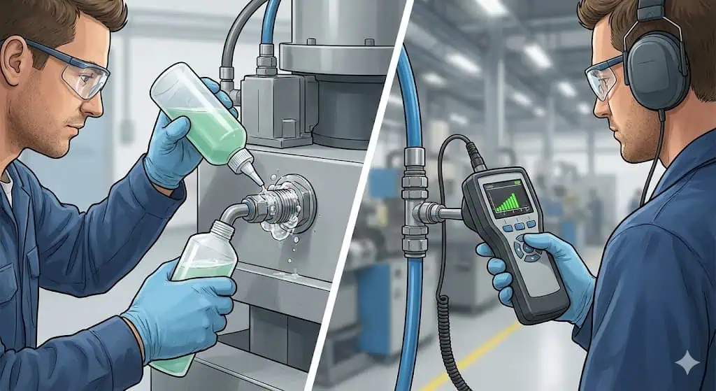
Leak testing is essential to confirm the integrity of your pneumatic fittings after installation. A good leak test is staged: quick gross-leak check, then a finer survey once the system is stable. Combine soap solution checks at joints with ultrasonic detection for small leaks in noisy areas. Treat pneumatic testing as hazardous stored-energy work and follow safety guidance such as ISO 4414 and recognized safety notes (UK HSE compressed air safety).
- Set a safe work area before pressurizing; keep unnecessary personnel away from stored-energy hazards.
- Use clean, dry air or nitrogen as the test medium where appropriate for your process.
- Increase pressure gradually, checking for leaks at each stage.
- Hold at the intended operating pressure long enough for temperature and seals to stabilize.
- Apply an approved leak detection solution at joints and mark any leaks for correction; follow up with ultrasonic detection for small leaks (Compressed Air Challenge resources).
Alert: Never use flammable substances for leak testing. If you are pressure testing beyond normal operating pressure, apply the correct procedure and risk controls for pneumatic testing.
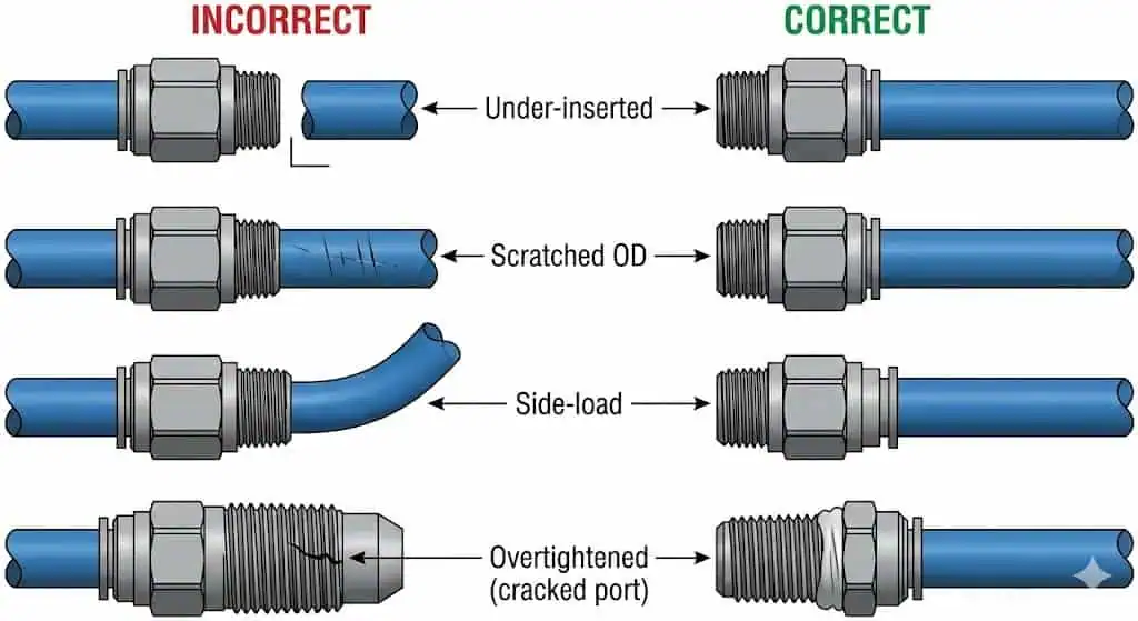
Common Installation Mistakes
Avoiding common mistakes during installation helps you maintain a safe and efficient pneumatic system. Most repeat failures fall into a short list:
- Over-tightening tapered threads, cracking polymer bodies or distorting ports (leak may appear later, not immediately).
- Under-inserting tubing into push-in fittings (tube looks seated but is not bottomed out).
- Using damaged tube ends (scratches at the seal line, ovality, heat-deformed ends).
Field example (overtightening): A maintenance tech chased a small thread leak by “one more turn.” The brass fitting survived, but the polymer manifold port cracked and started leaking after cooldown. Fix: replace damaged port component, use the correct thread type/adapter, and follow a controlled sealing method rather than brute force. Reference the correct thread standard and sealing expectation (ASME B1.20.1; ISO 228-1).
Tip: If you see recurring leaks at the same joint type, treat it like a process problem: standardize the method, add witness marks, and audit a sample of joints each shift.
Summary Table: Manufacturer Guidelines for Safe Installation
| Consideration | Description |
|---|---|
| System Requirements | Match pressure, duty cycle, and hazard controls to the machine and task |
| Environment | Confirm temperature, chemical exposure, vibration, and corrosion mode |
| Maintenance Needs | Plan access for inspection, leak survey, and safe depressurization |
| Compatibility | Standardize tubing spec and thread standards; label ports |
| Budget | Balance initial cost with documented reliability and service time |
By following these best practices, you can achieve reliable connections and reduce chronic leaks. The measurable target is stable pressure at the end use and a leak rate that trends downward after each maintenance cycle.
Maintenance and Troubleshooting
Inspecting for Leaks
You should inspect pneumatic fittings regularly to prevent leaks and maintain system safety.
A practical routine is a monthly walkdown for end-use connections plus a periodic ultrasonic survey. Leaks often start small; catching them early avoids pressure drift and excess compressor run time.
- Inspect common leak points (quick couplings, regulators, drop lines, tool whips, cylinder ports).
- Listen for hissing, but don’t rely on hearing in a production environment.
- Use soap solution for accessible joints; use ultrasonic detection for small leaks in noisy areas.
- Tag and log leaks; repair and verify with a re-test rather than “tighten and walk away.”
- Track leak rate trend—your maintenance effectiveness should show up as reduced leakage over time.
Tip: If the plant has never measured leak rate, start with one area (one line or one cell), fix what you find, and compare compressor loading before/after. This turns leak repair into a measurable improvement.
Cleaning and Upkeep
Proper cleaning and upkeep extend the life of your pneumatic fittings and prevent system failures.
Cleanliness and air quality are seal life. Water and particulate contamination accelerates wear and corrosion at the exact surfaces you need to remain smooth.
- Wipe down tools and fittings to remove dust and debris before disassembly.
- Use clean compressed air to blow out chips after cutting tubing (control where the chips go).
- Drain the compressor tank and manage moisture with filters/dryers appropriate to your service class (ISO 8573-1).
- Inspect tubing and fittings for abrasion marks near joints (often a sign of vibration or poor routing).
- Install and replace air filters on schedule; contamination costs more than filters.
- Include leak repair in routine maintenance because leaks can consume 20%–30% of compressor output in poorly maintained systems.
| Action | Schedule |
|---|---|
| Drain air line filters / check automatic drains | Weekly or as needed (more often in humid conditions) |
| Leak survey (soap checks + ultrasonic spot checks) | Every four weeks for critical cells; quarterly site survey |
| Externally clean components near joints | Every four weeks |
| Replace end-use filters per pressure drop indicator or schedule | Every six months (or earlier if DP rises) |
Note: Good upkeep reduces leaks and stabilizes pressure. Stable pressure reduces the temptation to “turn up the regulator,” which often hides root causes and increases consumption.
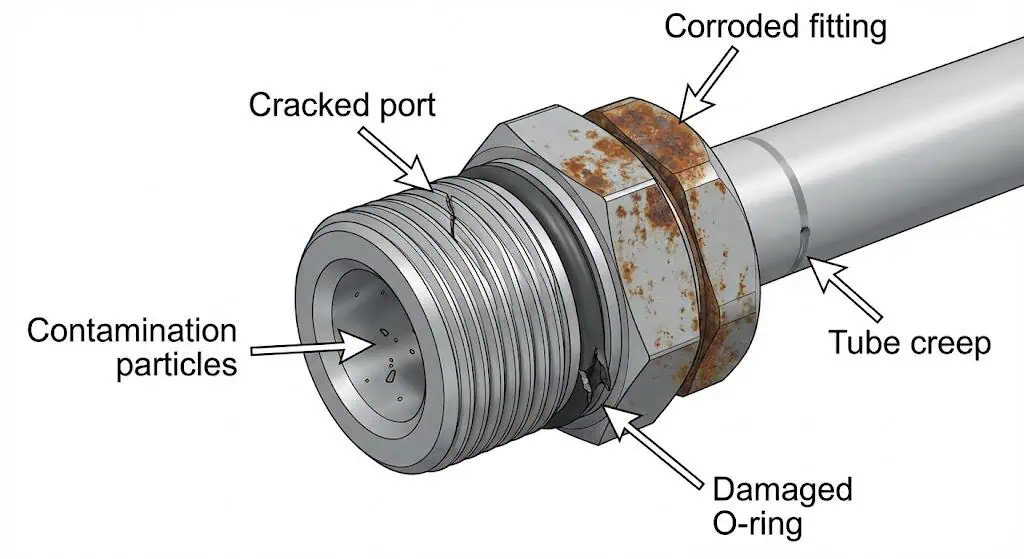
When to Replace Fittings
You need to replace pneumatic fittings when you see signs of wear, leaks, or damage.
Do not repeatedly “tighten” a joint that is failing—find the cause and replace the damaged interface. Replace fittings when you observe:
- Visible cracks, corrosion, deformed threads, or damaged sealing faces
- Persistent leaks after correct reassembly (clean tube end, verified thread standard, correct sealant/gasket)
- Contamination evidence (chips, rust particles, sticky valve behavior that traces to debris)
- Rising energy use attributable to leaks (especially when production hasn’t increased)
- Repeated repairs at the same joint type (signals a spec/standardization problem)
Alert: Replacing worn or damaged fittings is key to preventing leaks and keeping your pneumatics safe and reliable. Treat repeated failures as a standards/specification issue, not “bad luck.”
Troubleshooting Tip:
If you notice problems, isolate the affected area, depressurize safely, verify thread type and tube spec, and then reassemble using a controlled method (witness marks, correct insertion depth). Confirm repairs with a re-test and log the result.
You can maximize system efficiency and safety by following these essential steps for pneumatic fitting selection and installation:
- Material selection: Choose body + seal for your environment and media, not just “metal type.”
- Sizing: Match fittings to the tubing OD and tolerance; control tube cuts and insertion depth.
- Thread standards: Standardize NPT/BSP/metric and label ports to prevent cross-thread leaks.
- Leak control: Measure, tag, repair, and verify—then trend leak rate over time.
High-quality pneumatic fittings only deliver “leak-free” performance when the system controls are in place: verified standards, clean assembly, and documented methods.
Before starting any pneumatic project, use a selection checklist:
- Inspect tubing, couplings, and sealing surfaces
- Confirm thread standard and sealing method for each port
- Control cleanliness (chips from cutting/deburring)
- Ensure safe depressurization and PPE for assembly/testing
For complex needs (washdown, chemicals, hazardous locations, EU compliance), request documented specifications and certifications up front (e.g., PED documentation when applicable).
FAQ
What are the main benefits of using stainless steel pneumatic fittings?
Stainless steel can reduce corrosion risk and simplify washdown—when grade and seal materials match the environment.
In practice, corrosion performance depends on the stainless family and exposure (chlorides, acids, cleaners). Specify the exact grade and confirm seal compound (NBR vs FKM) because seals often set the true temperature/chemical limits.
How do you choose the right fittings for your pneumatic system?
Choose by documented compatibility: tube OD/tolerance + thread standard + seal material + pressure/temperature rating.
Start with tube OD and tubing datasheet, then lock down port thread standards (NPT vs BSPT/BSPP vs metric). Use recognized references for pneumatic safety and connector families (ISO 4414; ISO 14743). Finally, confirm air quality class and filtration/drying so seals and valves survive (ISO 8573-1).
Tip: Write the thread type and tube OD directly on the BOM line item. It prevents the most common mis-picks.
How often should you inspect pneumatic fittings for leaks?
Monthly is a practical baseline for production cells, with a periodic site-wide ultrasonic survey.
Well-maintained systems target lower leak rates; poorly maintained systems can waste ~20%–30% of compressor output to leaks. Use soap solution for accessible joints and ultrasonic detection for small leaks in noisy areas.
- Early detection prevents downtime and pressure instability
- Regular checks reduce energy waste and compressor run time
Can you reuse fittings after disassembly?
Sometimes—reuse only if the sealing and retention surfaces are undamaged and the reassembly method is controlled.
Push-to-connect and many threaded fittings can be reused if collets, seals, and threads are intact. Compression fittings depend on design and condition; follow the manufacturer’s guidance and do not reuse damaged ferrules.
| Fitting Type | Reusable? |
|---|---|
| Push-to-Connect | Yes (inspect collet/seal; re-cut tube end) |
| Compression | Sometimes (depends on ferrule design and condition) |
| Barbed | No (tube memory and pull-off risk increase) |
| Threaded | Yes (inspect threads and sealing face; reapply correct seal method) |
What should you do if you find a leak in your pneumatic system?
Isolate, depressurize safely, identify the leak mechanism, correct it, and verify with a re-test.
Do not “tighten until it stops.” Check for thread mismatch, damaged seal surfaces, under-inserted tubing, and contamination. After repair, verify with soap solution and/or ultrasonic detection and log the result.
Safety Tip: Depressurize and lock out where required, and wear eye protection during disassembly and testing.