
Your heat exchanger flange may leak due to:
- Thermal stress and flange distortion (loss of parallelism/flatness)
- Loose or improperly tightened bolts (insufficient preload)
- Gasket failure (wrong type, aging, creep/relaxation, installation damage)
- Overpressure and water hammer (transient loads exceeding gasket capacity)
- Corrosion and wear (pitting/crevice attack at the sealing band, face damage)
Why is my Heat Exchanger flange leaking? A small flange leak is rarely “small” in practice: it can wash out insulation, attack studs/nuts, accelerate corrosion under insulation, and contaminate product or utilities. A biochemical manufacturer, for example, faced high cost and lost production when a spiral heat exchanger’s gasket failed quickly. The sooner you identify the failure mode (thermal distortion vs. bolting vs. gasket vs. corrosion), the less likely you are to repeat the same leak after retightening.
Field safety note (before any troubleshooting): isolate the exchanger, depressurize to a verified zero-energy state, confirm medium hazards (steam, hot water, acids, hydrocarbons), and apply lockout/tagout. Do not “chase the leak” by tightening random bolts while the joint is hot or pressurized.
Why is my heat exchanger flange leaking?
Thermal Stress and Distortion
Direct Answer:
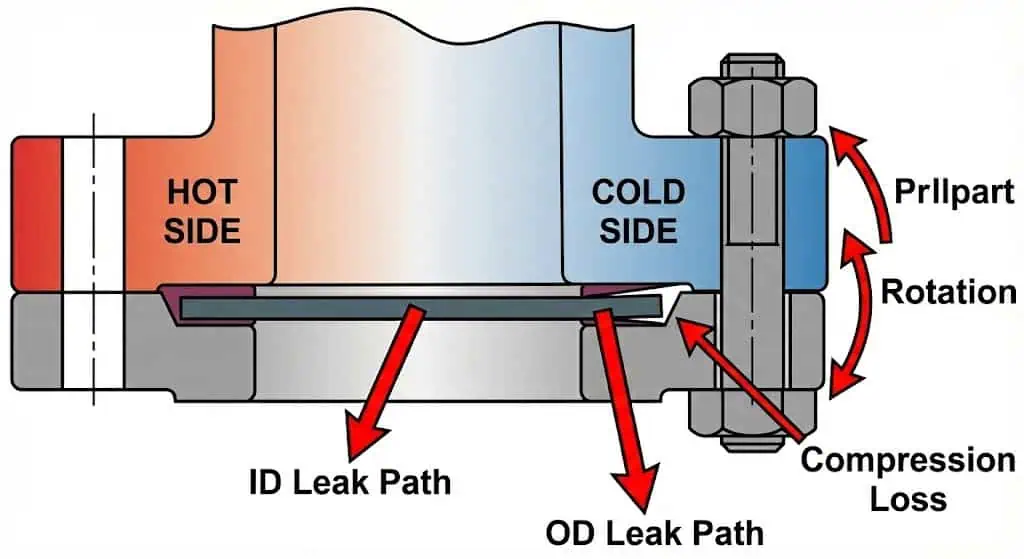
Rapid or extreme temperature changes create uneven thermal expansion across the flange and shell/nozzle, causing flange rotation, loss of gasket compression, and leakage.
In heat exchangers, the flange joint is not only loaded by internal pressure. It also sees bending from nozzle loads, piping restraint, and thermal gradients. If one side of the joint heats faster (startup on steam side, cold water on the other), the flange can warp enough to reduce gasket seating stress along part of the sealing band. When you operate under conditions with large temperature swings (example threshold often cited at 110°C / 230°F), distortion risk increases—typical field range, highly dependent on metallurgy, flange size/class, restraint, and ramp rate.
What thermal distortion looks like in the field: the leak starts after startup/shutdown, appears at one quadrant of the flange, and may reduce when the system stabilizes—then returns after the next cycle. If you find uneven flange gap around the circumference (measured with feeler gauges) or gasket imprint that is stronger on one side, you are dealing with rotation/distortion, not “just a loose bolt.”
Tip: Use controlled warm-up and cool-down procedures. On cyclic service, consider a gasket style with better recovery under thermal cycling (e.g., spiral wound with suitable filler and ring configuration) and verify nozzle loads/piping alignment before blaming the gasket.
Engineering example #1 (problem → cause → fix/prevention): A shell-and-tube exchanger on intermittent steam service leaked after every Monday startup. Root cause was fast steam admission creating a thermal gradient across the flange, plus piping strain pulling the nozzle. Fix was staged warm-up, piping support adjustment to remove nozzle bending, and a bolting procedure with staged tightening. Prevention: document the startup ramp and retorque strategy after the first heat cycle (when permitted by plant safety rules).
Loose or Improper Bolts
Direct Answer:
Bolts that are loose, unevenly tightened, or installed without a controlled procedure cannot maintain gasket compression, so the joint leaks.
“Bolt tightness” is actually bolt preload (tension). Preload scatter is common because friction varies with thread condition, lubrication, and nut-bearing surface. If the joint was assembled without a defined method (cleaning, lubrication, cross-pattern, staged torque), the gasket may never reach its required seating stress. Maintenance data frequently shows improper assembly as a leading contributor; one commonly cited figure is that a large share of gasket failures are linked to installation issues. The practical takeaway: treat bolting as a controlled process, not a “hand feel” task.
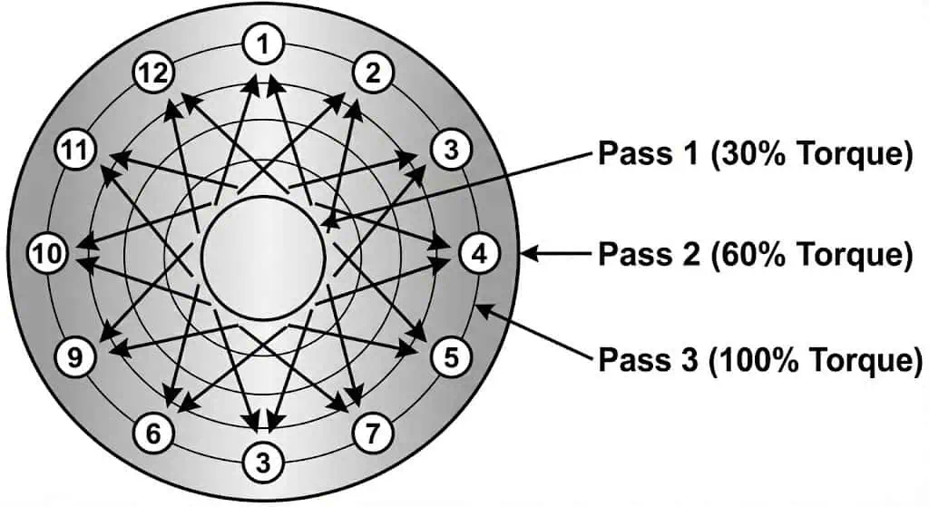
- Use a defined bolting method: cross-pattern, multiple passes, and staged tightening (example: 30% → 60% → 100%).
- Control friction: clean threads, check for galling, and lubricate threads/nut faces consistently.
- Verify even compression: measure flange gap at multiple points and look for uneven gasket imprint after disassembly.
Hardware reality check: stud/nut grades (e.g., ASTM A193/A194 series commonly specified in many plants) and material pairing (stainless on stainless) affect galling risk and achievable preload. If you see torn threads, shiny smear marks, or nuts that “stick,” the joint may never have been properly loaded.
Engineering example #2 (problem → cause → fix/prevention): A plate heat exchanger leaked on one side after a gasket change. The crew tightened clockwise in a circle (not cross-pattern), leaving one quadrant underloaded. Fix was to replace the damaged gasket, clean the faces, and tighten in a star pattern with staged passes. Prevention: use a written bolting checklist and mark bolt numbers on the flange to enforce the sequence.
Gasket Issues
Direct Answer:
Wrong gasket type, gasket aging, creep/relaxation, or installation damage will reduce sealing stress and cause leakage.
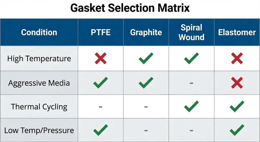
Gaskets seal by maintaining contact stress on the sealing band. If the gasket creeps (cold flow) or relaxes under temperature and pressure, bolt preload effectively “disappears” from the gasket interface. PTFE-based gaskets can creep under sustained load; compressed fiber gaskets may lose resiliency in hot service; flexible graphite generally performs better under higher temperature and aggressive media—subject to oxidation limits and proper grade selection.
Installation damage is common and avoidable: nicks on the gasket edge, mis-centering, contamination on the flange face, or reusing a compressed gasket can create a leak path that no amount of extra torque will permanently solve.
| Gasket Material | Prone to Failure Characteristics (What fails and why) |
|---|---|
| Skived Virgin PTFE | Creep/cold flow; loss of bolt load retention over time; sensitivity to surface finish and seating stress |
| Compressed Fiber | Lower recovery at elevated temperature; chemical limits depending on binder; can stick to faces after cycling |
| Flexible Graphite | Better high-temperature performance and chemical resistance in many services; requires correct grade and oxidation control |
| Elastomers | Compound-dependent swelling/aging; temperature limits; must match fluid compatibility |
Note: If a leak repeats after “retorque,” treat it as a gasket/joint design problem (gasket style, face condition, flange rotation, bolt load control), not a simple tightening problem. Replace the gasket and fix the cause; do not reuse gaskets.
Engineering example #3 (problem → cause → fix/prevention): A cooling-water exchanger used a PTFE gasket in a bolted joint with frequent temperature cycling. The gasket crept, preload dropped, and a small seep became a steady leak. Fix was to switch to a gasket better suited to cycling and to apply a controlled bolting procedure with consistent lubrication. Prevention: choose gasket materials based on load retention and cycling behavior, not only chemical resistance.
Overpressure and Water Hammer
Direct Answer:
Transient pressure surges (water hammer, rapid valve closure, pump trips) can momentarily exceed gasket capacity, disrupt seating, and initiate leakage.
Water hammer occurs when flow changes rapidly and creates a pressure wave. Even if normal operating pressure is within the flange class rating, a surge can momentarily spike load and force gasket extrusion or face separation at a local point. You may not see immediate catastrophic failure; instead, you get a “new leak” that appears after the transient event.
- Watch for sudden banging noises, vibration, or gauge needle “snap.”
- Review valve closure times and pump trip sequences; these are frequent triggers.
- Use relief devices, surge suppression, and properly selected check valves to reduce peak transients.
Engineering example #4 (problem → cause → fix/prevention): A utility-water exchanger started leaking right after an emergency stop. Investigation found a fast-closing valve created water hammer, shifting gasket seating. Fix included changing to a damped check valve/actuation strategy and verifying that the joint was reassembled with even bolt load. Prevention: treat surge control as part of flange leak prevention, not a separate “piping issue.”
Corrosion and Wear
Direct Answer:
Corrosion and physical wear damage the flange face and reduce sealing reliability, leading to chronic leakage.
Heat exchanger flanges commonly see crevice corrosion at the gasket interface (oxygen differential), pitting in chloride-bearing services, and erosion where high-velocity fluid or entrained solids impact surfaces. Once the sealing band is pitted or scratched across the gasket contact zone, the joint may leak even with “correct torque.” If you see thinning, pitting, or rough sealing surfaces, do not assume a new gasket alone will fix it—face restoration and material review may be required.
| Material Type | Corrosion Resistance Characteristics (Practical selection notes) |
|---|---|
| Stainless Steel | Generally good resistance to many services; risk of pitting/crevice corrosion in chlorides depends on grade and temperature |
| Nickel Alloys | Often selected for aggressive media and higher temperature corrosion resistance |
| Duplex Stainless Steels | Higher strength and improved resistance in many chloride-containing environments; selection depends on process chemistry |
Tip: Inspect the sealing band for pits, radial scratches, and corrosion under the gasket. If damage crosses the sealing path, plan for face resurfacing or flange replacement, not repeated retightening.
Table: Most Frequently Reported Causes of Heat Exchanger Flange Leaks
| Cause | Explanation |
|---|---|
| Thermal Stress & Flange Distortion | Thermal gradients and restraint cause flange rotation/warping and uneven gasket compression. |
| Loose or Improperly Torqued Bolts | Uneven preload, friction scatter, and relaxation reduce gasket seating stress and open leak paths. |
| Inadequate Hardware or Gasket Design | Gasket type/geometry not suited to cycling or media; bolt/stud condition or grade limits achievable preload. |
| Surface Damage or Corrosion at the Sealing Band | Pitting, crevice corrosion, or scratches cross the sealing path; gasket cannot compensate for face defects. |
| Transient Overpressure / Water Hammer | Pressure surges disrupt seating or extrude the gasket locally, initiating a leak after the event. |
If you ask, “why is my heat exchanger flange leaking?”, start by identifying the dominant failure mode (thermal distortion vs. preload loss vs. gasket mismatch vs. corrosion). Fixing the symptom (retorque) without fixing the mechanism is why many flange leaks return after the next cycle.
Fixing and Preventing Heat Exchanger Flange Leaks
Inspect and Tighten Bolts
Direct Answer:
Use a controlled tightening method (pattern + stages + consistent lubrication) and verify even flange compression to maintain a sealed joint.
Bolting is the highest-leverage control point you have in the field. You should inspect studs/nuts for corrosion, thread damage, and galling; clean contact surfaces; and use a calibrated torque wrench or tensioning method suitable for the joint. Tighten bolts in a cross-pattern to avoid flange rotation. This approach aligns with common best-practice guidance for gasketed bolted joints (often referenced in plant procedures based on recognized standards such as ASME PCC-1).
Practical bolt-tightening checklist (field-ready):
- Confirm gasket type and dimensions match the flange facing and bore.
- Clean flange faces and remove old gasket residue without gouging the sealing band.
- Check flange parallelism and alignment (do not “pull” misalignment with bolts).
- Lubricate threads and nut-bearing surfaces consistently (same lubricant, same coverage).
- Tighten in a star/cross pattern with staged passes (example: 30% → 60% → 100%).
- Verify even gap around the flange after each stage; correct before final pass.
You should inspect bolts for signs of wear or looseness. Use a torque wrench and tighten bolts in a staggered pattern. Always measure the distance between flanges at several points to ensure even tightening. For larger bolts, staged torque application reduces distortion and helps seat the gasket evenly. Use manufacturer guidance for hydraulic tensioners when specified.
| Frequency Category | Inspection Interval | Conditions |
|---|---|---|
| High Frequency | Every 1-6 months | Hazardous, high pressure, or toxic service |
| Medium Frequency | Every 6-12 months | General service, moderate conditions |
| Low Frequency | 12-24 months | Non-critical, low-pressure service |
Replace or Upgrade Gaskets
Direct Answer:
Replace any gasket that has been compressed or exposed to service, and upgrade gasket type when cycling, media, or flange condition demands better load retention.
Gasket life depends on temperature, pressure, cycling frequency, surface finish, and media compatibility. Many operators use a typical replacement window of three to five years, but harsh service can shorten it significantly. If a leak started after an operating change (higher temperature, new chemical, more cycling), treat the gasket as a design variable, not a consumable commodity.
Upgrade triggers engineers use on exchangers:
- Frequent thermal cycles causing relaxation → consider gaskets with better recovery and controlled compression.
- High differential pressure pushing gasket inward/outward → select appropriate ring configuration and anti-blowout features where applicable.
- Chemical exposure swelling/softening elastomers → switch compound or material system based on compatibility.
Some operators prefer gasket designs that allow faster maintenance and reduced downtime; for example, systems highlighting easy replacement and service flexibility are discussed by equipment suppliers such as Tranter. Use these as practical considerations, but always anchor the selection to your pressure/temperature/media envelope.
| Advantage | Description |
|---|---|
| Quick Replacement | Reduces outage time when gaskets are designed for serviceability |
| Versatility | Different gasket materials handle different media and temperature limits |
| Operational Efficiency | Stable sealing reduces rework, retorque cycles, and leak-related cleanup |
Tip: Always match gasket material to your operating conditions, and do not reuse gaskets. A reused gasket is a controlled leak waiting to happen.
Address Thermal Expansion
Direct Answer:
Reduce thermal gradients and manage thermal growth so flange faces remain parallel and gasket stress remains stable.
Thermal expansion control is part design and part operation. Expansion joints absorb movement from temperature changes, while piping supports and nozzle load management prevent bending loads from rotating the flange. If the exchanger sees repeated hot/cold switching, review startup/shutdown ramp rates and consider whether the piping arrangement is “locking” the nozzle and forcing the joint to carry bending.
- Expansion joints absorb pipe growth and contraction.
- They reduce bending stress on flange connections.
- They help prevent gasket stress loss during cycling.
Control Pressure and Water Hammer
Direct Answer:
Reduce transient surges using valve control strategies, check valve selection, and surge/relief protection so momentary loads do not disrupt gasket seating.
Choose check valves that close smoothly to avoid water hammer. Actuation strategies (slower closure, damping) reduce sudden pressure changes. Automated pressure control and tuned valve sequencing can meaningfully reduce transient peaks. Research literature discusses surge mitigation and transient behavior, including studies such as this water-hammer related publication. Your goal is not “zero surge,” but keeping peak transients within the joint’s sealing margin.
| Key Findings | Description |
|---|---|
| Pressure Management | Maintaining stable operating conditions reduces joint stress and leak recurrence |
| Transient Control | Valve sequencing, damped check valves, and relief/surge devices reduce peak events that disrupt sealing |
Regular Maintenance and Quality Flanges
Direct Answer:
Use a documented inspection schedule, verify face condition, and maintain traceable hardware so flange joints remain repeatable across maintenance cycles.
You should inspect, clean, and test your heat exchanger flange joints regularly. Focus on face condition (pitting/scratches across the sealing band), bolt condition (corrosion and thread damage), and gasket storage/handling. Many plants base their flange assembly procedures on recognized guidance such as ASME PCC-1, and heat exchanger mechanical expectations are often aligned with TEMA conventions (project/spec dependent). Where corrosion is recurring, review metallurgy and process chemistry rather than repeatedly changing gaskets.
- Monthly: Visual checks for weeping, rust trails, insulation wetting, and nut back-off markers.
- Quarterly: Verify bolt condition, inspect for corrosion under insulation, and clean external surfaces where safe.
- Annually (or during planned outage): Disassemble as needed, inspect faces, replace studs/nuts if degraded, and document gasket imprint and any flange rotation evidence.
Note: If the joint repeatedly leaks after correct assembly, escalate to an engineering review: flange facing suitability, gasket selection for cycling, nozzle loads, alignment, and transient pressure events.
Act quickly when you notice persistent leaks at a flange.
You prevent costly repairs by inspecting for corrosion and stress corrosion cracking indicators. Regular cleaning and routine inspections help you spot corrosion, rust, and face damage early.
- Consult specialists when recurring leaks suggest a design or metallurgy issue (not a gasket-only issue).
- Keep joint history (gasket type, bolt condition, torque method, leak location) to identify repeating mechanisms.
- Plan maintenance so you can correct alignment/nozzle load issues instead of compensating with extra torque.
FAQ
What should you do first if you spot a flange leak?
Direct Answer:
Isolate and depressurize the system safely before any mechanical action.
After shutdown/LOTO and pressure verification, inspect for obvious causes: loose nuts, gasket extrusion, rust trails, and misalignment. Avoid tightening a hot or pressurized joint.
How often should you replace heat exchanger gaskets?
Direct Answer:
A common maintenance window is 3–5 years, but service conditions can shorten it.
If you see leaks, chemical attack, hardening, cracks, or creep/relaxation, replace sooner. Do not reuse compressed gaskets.
Why choose stainless steel flanges for heat exchangers?
Direct Answer:
Stainless steel flanges often provide better corrosion resistance for wet, chloride-bearing, or chemical services.
Selection still depends on chemistry and temperature. For recurring pitting/crevice corrosion at the gasket interface, review grade selection and surface condition, not only bolt torque.
Why does a leak return after retightening?
Direct Answer:
Retightening may temporarily increase compression, but it does not correct distortion, face damage, gasket creep, or misalignment.
If the leak repeats after the next thermal cycle, investigate flange rotation, gasket suitability for cycling, and surface condition of the sealing band.
What flange checks prevent repeat leaks during reassembly?
Direct Answer:
Face inspection + alignment verification + controlled bolting + correct gasket handling.
Check for pits/scratches across the sealing band, verify parallelism, ensure correct gasket centering, lubricate consistently, and tighten in a cross-pattern with staged passes.


