Weld Neck Flanges • High-Integrity Connections
Weld Neck Flanges (WN) for High-Pressure & High-Cycle Service
When vibration, temperature cycling, or tight leak-rate targets are part of the job, Weld Neck (WN) flanges are often the safest starting point. The tapered hub improves alignment and stress distribution, and the butt-weld end can be qualified and inspected per project code.
Standards ASME B16.5 (NPS 1/2–24) • ASME B16.47 (NPS 26–60) • EN 1092-1 • JIS B2220
Classes 150 / 300 / 600 / 900 / 1500 / 2500
Facing RF / FF / RTJ
Materials 304/304L, 316/316L, 2205, 2507
Docs EN 10204 3.1 MTR + Heat No. traceability
* ISO 9001 quality system • EN 10204 3.1 MTR (heat-number traceability) • PMI available • Dimensional inspection records • NDT available per project specification
Types of Weld Neck Flanges We Supply
 Stainless Steel Flanges
By Design Type
By Standard & Class
Advanced Materials
4-Bolt Stainless Steel Weld Neck Flange, Raised Face (RF)
4-Bolt SS304 Weld Neck Flange, ASME B16.5 Class 150 RF
4-Bolt SS316L Weld Neck Flange, PN16 Raised Face (RF)
4-Bolt Stainless Steel Weld Neck Flange, DIN Standard RF
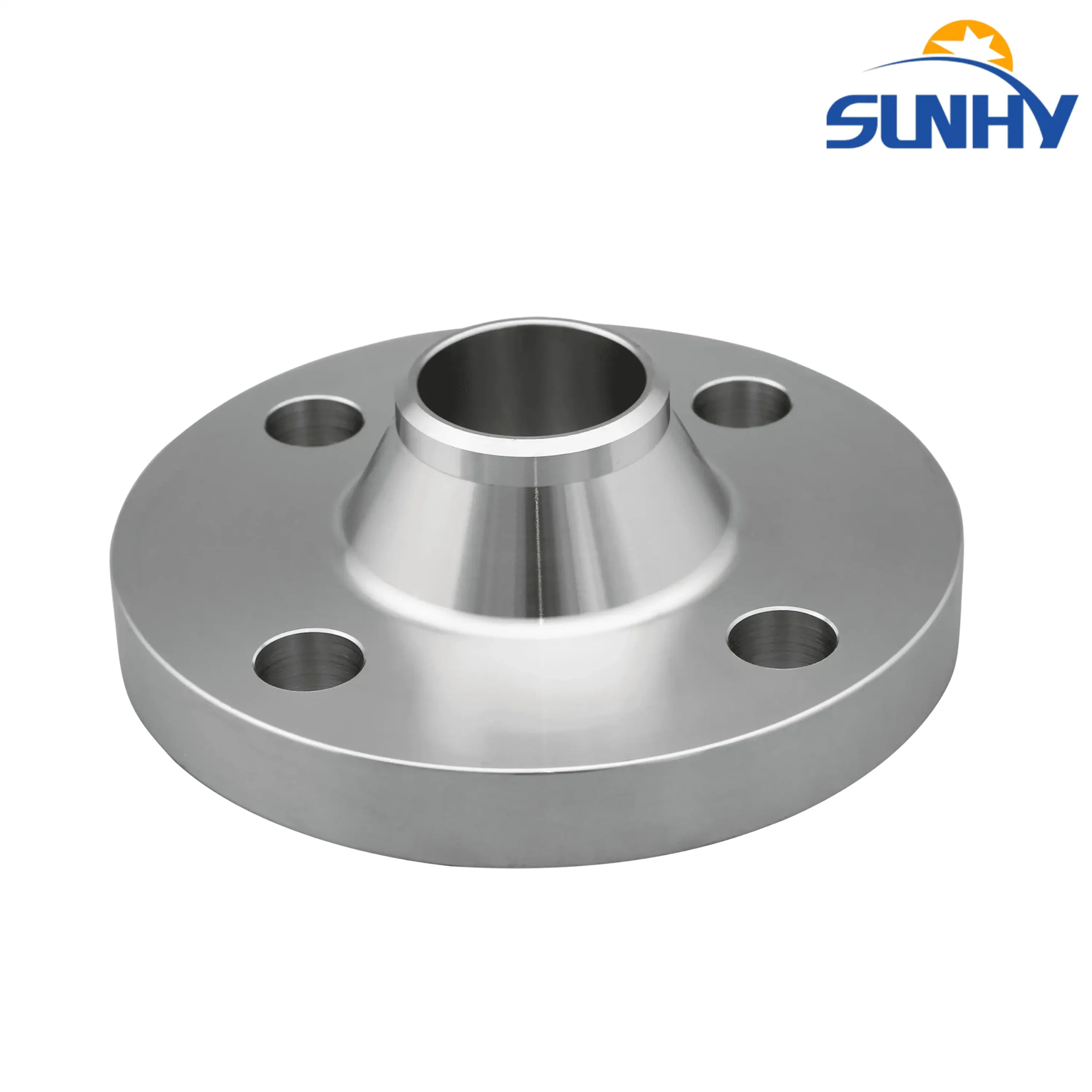
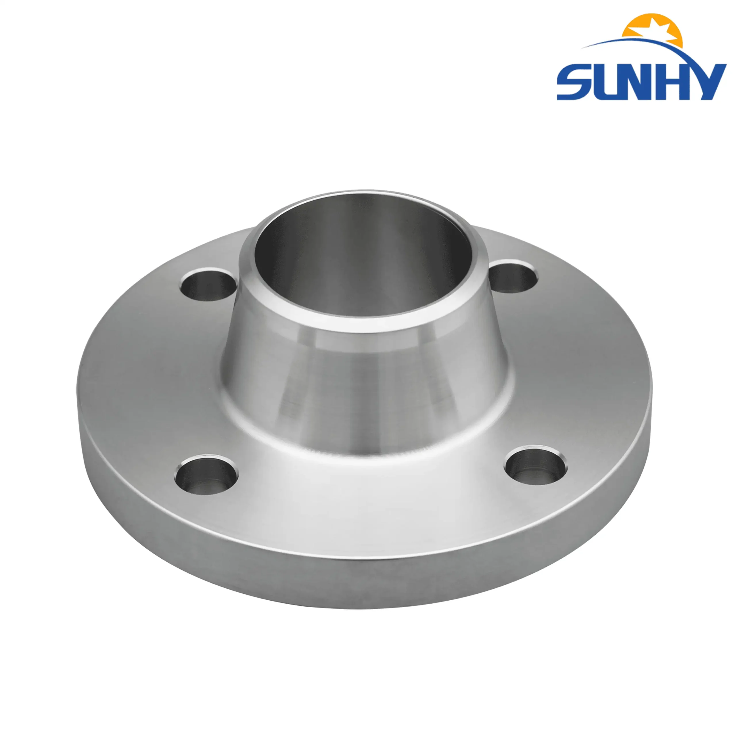
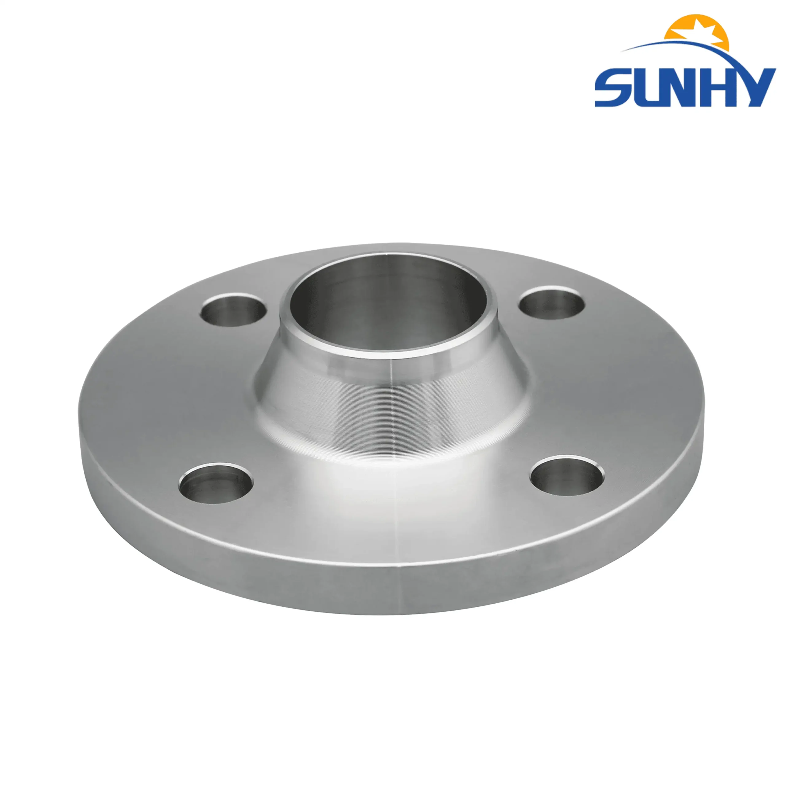
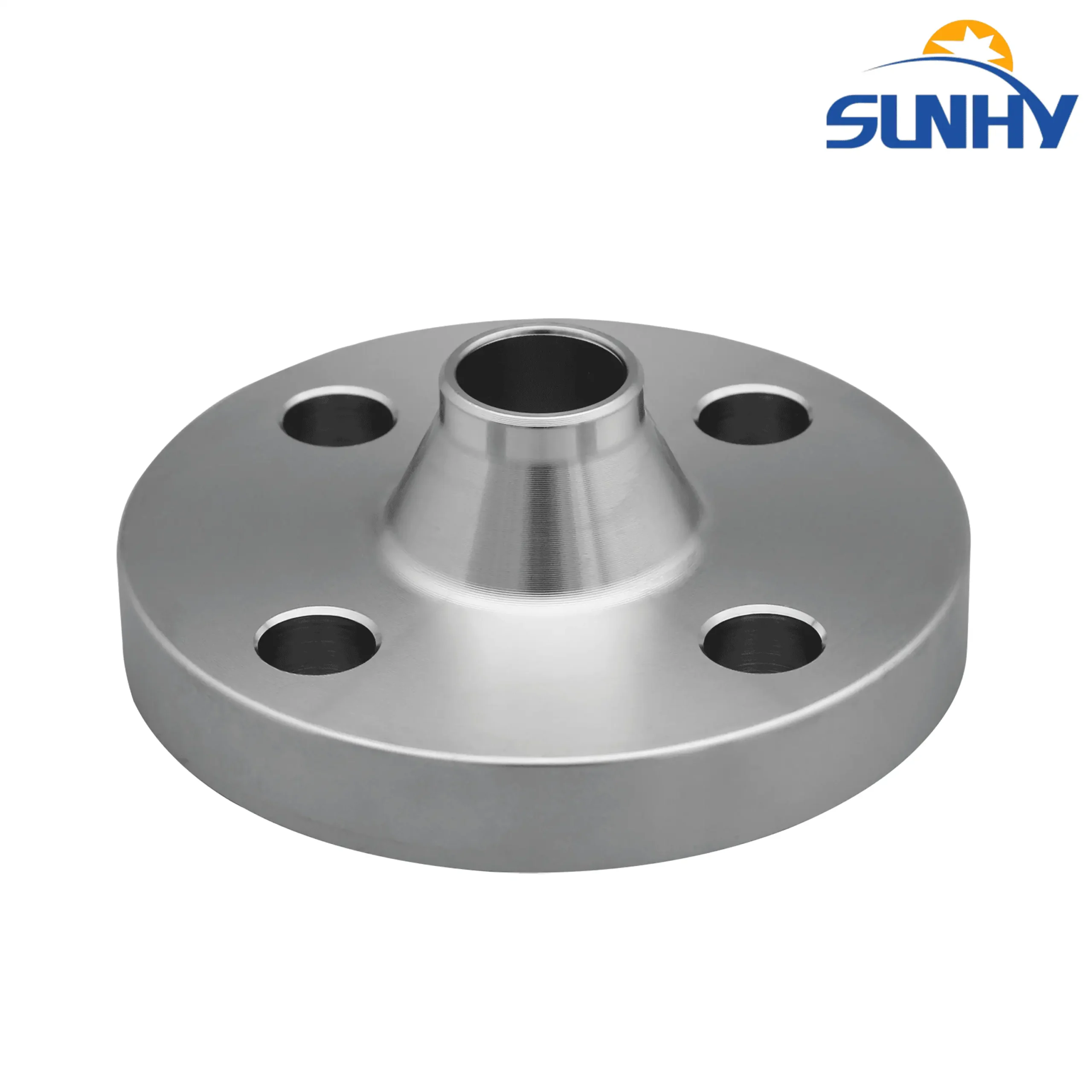
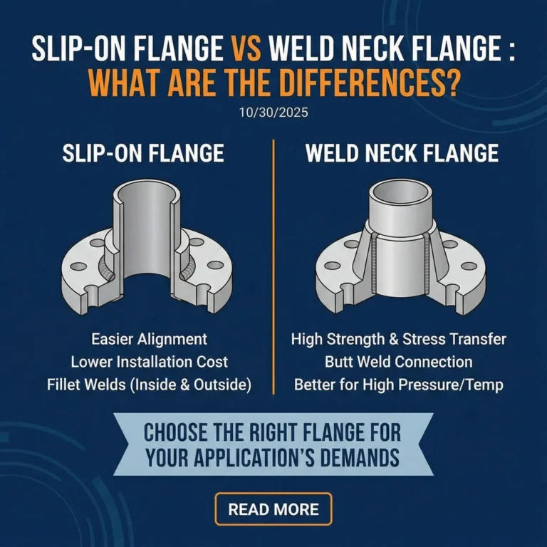
What is a Weld Neck Flange
A weld neck flange (WN) is a forged, hubbed flange used to connect pipe ends through a butt-weld. It is commonly specified when joint integrity matters—such as higher-pressure service, vibration, thermal cycling, or applications with tighter leak-rate requirements.
A typical sealing system includes the flange facing, gasket, and bolting. Weld neck flanges can be manufactured from stainless steel and nickel alloys (e.g., Hastelloy) and supplied to the required standard and project specification, such as ASME B16.5/ASME B16.47, EN 1092-1 (DIN), JIS B2220, or the applicable ISO series. Always confirm the mating flange standard and bolt pattern before ordering.

When WN is a smart default
- High vibration (compressor discharge, rotating equipment lines)
- Thermal cycling (steam, hot oil, frequent start/stop)
- Higher class joints where bolt load and flange stiffness matter
- Tight leak targets where joint control is part of QA
When another flange may be better
- Low pressure utility where cost and speed dominate (often slip-on)
- Frequent dismantling with special constraints (depends on design)
- Space-limited fabrication where weld access is restricted
If you share your service conditions, we can recommend a joint concept—WN isn’t always the answer.
How to Specify Weld Neck Flanges
A clean RFQ reduces back-and-forth and prevents mismatched bore, facing, or bolt patterns. Here is the exact specification string we like to see from EPCs and maintenance teams.
Practical warning
| Item | What to provide | Why it matters |
|---|---|---|
| Standard | ASME B16.5 or ASME B16.47 (Series A/B) | Controls bolt pattern, OD, and key dimensions |
| Size | NPS (inches) + Qty | Determines bore and welding details |
| Pressure class | 150 / 300 / 600 / 900 / 1500 / 2500 | Defines thickness and bolting pattern |
| Facing | RF / FF / RTJ + (ring type if RTJ) | Sealing system compatibility |
| Material | 304/304L, 316/316L, 2205, 2507, [others] | Corrosion + strength + code compliance |
| Bore / Schedule | Pipe schedule or required bore (match pipe OD/ID requirements) | Prevents mismatch during fit-up |
| Inspection & docs | EN 10204 3.1 MTR, PMI, dimensional report, [NDT if required] | QA acceptance + traceability |
| Special notes | Coating, marking, packing, export docs, project spec references | Reduces site delays and rework |
Engineering Tools
Dimensions & Bolt Patterns
Download PDF/Excel for Class 150–2500 and large diameter (B16.47).
NPS 1/2″–24″ (B16.5)
26-60″+ (B16.47)
RF / FF / RTJ
Facing & Gasket Selection Guide
Stop leaks by matching facing, gasket type, and service.
Engineer note
RTJ is not “better by default”—it’s a system choice. If the mating flange or ring spec is wrong, RTJ can fail just as badly.
Bolting & Joint Integrity Checklist
Bolting & Joint Integrity Checklist A practical checklist that reduces rework and commissioning delays.
Weld Neck Flanges (WN) Specifications
Standard Compliance & Performance
Designed for the most critical applications, our Weld Neck flanges strictly adhere to ASME B16.5 standards covering all pressure ratings from Class 150 through Class 2500.
High Integrity: The long, tapered hub reinforces the flange and transfers stress from the flange to the pipe, making it the superior choice for high-pressure, high-temperature, and cyclic loading conditions.
Inspection Ready: The butt-weld connection allows for full radiographic (RT) or ultrasonic inspection of the joint, ensuring maximum safety reliability.
Material & Installation
Manufactured from premium Forged Steel (Carbon, Stainless, and Alloy) to ensure grain flow continuity.
Flow Optimization: The flange bore is machined to match the ID of the mating pipe, reducing turbulence and erosion at the connection point.
Dimensional Reference
Refer to the cross-section diagram and table headers for key measurements:
O / OD: Outside Diameter
X: Diameter at Base of Hub (Structural support)
Y / H: Length through Hub
BC: Bolt Circle Diameter
Critical Technical Note: When ordering Weld Neck flanges, you must specify the Pipe Schedule (e.g., Sch 40, Sch 80, XS). The flange ID must match the pipe ID exactly to prevent flow restriction and ensure a proper butt weld.

Weld Neck Flange (WN) Dimensions
Unit: Millimeters (mm)ASME B16.5 Class 150 WN
| NPS (Size) |
Outside Dia (O) (mm) |
Hub Dia (X) (Base of Hub) |
Length (Y) (Through Hub) |
Bolt Circle (BC) (mm) |
Holes (Qty) |
Bolt Size (Inch) |
|---|---|---|---|---|---|---|
| 1/2" | 88.9 | 30.2 | 47.8 | 60.5 | 4 | 1/2" |
| 3/4" | 98.6 | 38.1 | 52.3 | 69.9 | 4 | 1/2" |
| 1" | 108.0 | 49.3 | 55.6 | 79.2 | 4 | 1/2" |
| 1-1/2" | 127.0 | 65.0 | 61.9 | 98.6 | 4 | 1/2" |
| 2" | 152.4 | 77.7 | 63.5 | 120.7 | 4 | 5/8" |
| 3" | 190.5 | 108.0 | 69.9 | 152.4 | 4 | 5/8" |
| 4" | 228.6 | 134.9 | 76.2 | 190.5 | 8 | 5/8" |
| 6" | 279.4 | 192.0 | 88.9 | 241.3 | 8 | 3/4" |
| 8" | 342.9 | 246.1 | 101.6 | 298.5 | 8 | 3/4" |
| 10" | 406.4 | 304.8 | 101.6 | 362.0 | 12 | 7/8" |
| 12" | 482.6 | 365.3 | 114.3 | 431.8 | 12 | 7/8" |
| 16" | 596.9 | 457.2 | 127.0 | 539.8 | 16 | 1" |
| 20" | 698.5 | 558.8 | 144.5 | 635.0 | 20 | 1-1/8" |
| 24" | 812.8 | 663.4 | 152.4 | 749.3 | 20 | 1-1/4" |
ASME B16.5 Class 300 WN
| NPS (Size) |
Outside Dia (O) (mm) |
Hub Dia (X) (Base of Hub) |
Length (Y) (Through Hub) |
Bolt Circle (BC) (mm) |
Holes (Qty) |
Bolt Size (Inch) |
|---|---|---|---|---|---|---|
| 1/2" | 95.3 | 38.1 | 52.3 | 66.5 | 4 | 1/2" |
| 1" | 124.0 | 53.8 | 61.9 | 88.9 | 4 | 5/8" |
| 2" | 165.1 | 84.1 | 69.9 | 127.0 | 8 | 5/8" |
| 3" | 209.6 | 117.3 | 79.2 | 168.1 | 8 | 3/4" |
| 4" | 254.0 | 146.1 | 85.9 | 200.2 | 8 | 3/4" |
| 6" | 317.5 | 206.2 | 98.6 | 269.7 | 12 | 3/4" |
| 8" | 381.0 | 260.4 | 111.3 | 330.2 | 12 | 7/8" |
| 10" | 444.5 | 320.5 | 117.3 | 387.4 | 16 | 1" |
| 12" | 520.7 | 374.7 | 130.0 | 450.9 | 16 | 1-1/8" |
ASME B16.5 Class 600 WN
| NPS (Size) |
Outside Dia (O) (mm) |
Hub Dia (X) (Base of Hub) |
Length (Y) (Through Hub) |
Bolt Circle (BC) (mm) |
Holes (Qty) |
Bolt Size (Inch) |
|---|---|---|---|---|---|---|
| 1/2" | 95.3 | 38.1 | 52.3 | 66.5 | 4 | 1/2" |
| 1" | 124.0 | 53.8 | 61.9 | 88.9 | 4 | 5/8" |
| 2" | 165.1 | 84.1 | 73.2 | 127.0 | 8 | 5/8" |
| 4" | 273.1 | 152.4 | 101.6 | 215.9 | 8 | 7/8" |
| 6" | 355.6 | 222.3 | 117.3 | 292.1 | 12 | 1" |
| 8" | 419.1 | 273.1 | 133.4 | 349.3 | 12 | 1-1/8" |
| 12" | 558.8 | 381.0 | 155.4 | 489.0 | 20 | 1-1/4" |
For Classes 900, 1500 and 2500, dimensions follow the same ASME B16.5 pattern with increased thickness and bolt sizes.
Check Full ASME Class 600–2500 TablesHigh Pressure Snapshot – Class 1500
Note: For high pressure WN flanges, pipe wall thickness (schedule) and material grade must be specified in addition to flange dimensions.
| NPS (Size) |
Outside Dia (O) (mm) |
Hub Dia (X) (Base of Hub) |
Length (Y) (Through Hub) |
Bolt Circle (BC) (mm) |
Holes (Qty) |
Bolt Size (Inch) |
|---|---|---|---|---|---|---|
| 2" | 215.9 | 104.6 | 101.6 | 165.1 | 8 | 7/8" |
| 3" | 266.7 | 133.4 | 117.3 | 203.2 | 8 | 1-1/8" |
| 4" | 311.2 | 162.1 | 123.9 | 241.3 | 8 | 1-1/4" |
| 6" | 393.7 | 228.6 | 171.5 | 317.5 | 12 | 1-3/8" |
| 8" | 482.6 | 292.1 | 212.8 | 393.7 | 12 | 1-5/8" |
Need API 6A 10,000 / 15,000 psi wellhead flanges?
View API 6A Wellhead StandardsLarge Diameter Weld Neck Flanges – ASME B16.47
For pipe sizes from 26" to 60", ASME B16.47 applies. Sunhyings manufactures both Series A (MSS SP-44) and Series B (API 605) large diameter Weld Neck flanges.
Materials & Service Notes
Material selection is where a “catalog page” becomes a decision page. Below is conservative guidance we use when helping teams avoid corrosion surprises and maintenance headaches.
304/304L vs 316/316L
- 304/304L: good general purpose choice for mild corrosion and indoor/utility service.
- 316/316L: my default when chlorides or marine exposure are likely (still confirm limits by spec).
- “L” grades: typically preferred for weldability and reduced sensitization risk.
If you have temperature + chloride + stagnation together, don’t guess—share conditions and we’ll propose a safer option.
Duplex 2205 / Super Duplex 2507
- 2205: higher strength and often chosen when corrosion resistance needs to step up beyond 316L.
- 2507: used in more aggressive chloride environments; requires disciplined fabrication and QA control.
Important: welding procedure and QA matter as much as the base metal.
Facing, Sealing & Bolting
A flange is part of a bolted joint system. The highest ROI improvements usually come from correct facing selection, clean gasket handling, and controlled bolting—especially during commissioning.
RF (Raised Face)
Common across ASME piping. Works well with many gasket types when surface finish and bolt load are controlled.
If you want a safe default for standard services, RF is often the starting point.
FF (Flat Face)
Often specified for cast iron or when a full-face gasket is required by project spec.
Confirm the mating flange requirement—mixing FF/RF incorrectly can cause issues.
RTJ (Ring Type Joint)
Chosen when RTJ is specified for higher integrity sealing. Requires correct ring type and groove spec.
RTJ failures are usually system failures: wrong ring, damaged groove, or improper assembly.
Bolting checklist
1. Verify Alignment & Gap · 2. Inspect Gasket & Lubricate Threads · 3. Apply Star Pattern Sequence · 4. Multi-pass to Final Torque. View the Complete ASME PCC-1 Guidelines
Engineering Cases & Practical Solutions
Case 1: Vibration on compressor discharge
Seepage returned after several start-up/shutdown cycles on a vibrating discharge line, even after gasket replacement and re-torque.
Switched to Weld Neck (WN) for better alignment and reduced joint bending
Matched facing finish + gasket type to the service condition
Standardized bolt-up: lubrication, star pattern, staged torque, final verification
Practical outcome
Leak recurrence stopped and joint stability improved under vibration.
Case 2: Chloride exposure in coastal utility system
Coastal air and splash-zone exposure accelerated corrosion risk around bolting and sealing surfaces, increasing leak and rework potential.
Upgraded material strategy to 316L / duplex based on chloride risk and temperature
Added receiving controls: traceability + PMI checks for critical lots
Protected machined faces during storage/handling to prevent crevice initiation
Practical outcome
Less corrosion-related rework and more consistent sealing performance over maintenance cycles.
Case 3: Thermal cycling on steam / hot oil lines
Frequent start/stop and thermal expansion cycles increased leak risk due to preload loss and fit-up stress.
Confirmed correct standard + class for stiffness under cycling
Matched gasket and facing to the temperature range and cycle profile
Controlled installation: alignment first, avoid pull-to-fit, staged tightening
Practical outcome
More repeatable performance across cycles and reduced leak-up during heat-up/cool-down.
Quality, Traceability & “Proof Pack”
If you are sourcing internationally, what matters is not what a supplier says—they need to show consistent traceability and inspection discipline.
What we can provide per shipment
- EN 10204 3.1 MTR with Heat No. traceability
- PMI record (as required)
- Dimensional inspection key items per standard
- NDT reports (UT/RT/PT/MT) if specified
- Marking list: NPS, class, material, standard, heat
Add your real sample links for trust (redact sensitive info).
Sample 3.1 MTR (redacted) • Sample PMI / inspection • ISO certificate
Process snapshot (high-level)
- Raw material control → forging → heat treatment (as required)
- CNC machining → facing finish control → marking
- Inspection & verification → surface protection → export packing
Engineer note
For critical service, the “last 5%” matters: sealing surface protection, correct facing, and documentation discipline. If you want repeat orders from EPCs, publish evidence—photos, reports, and traceability.
RFQ Checklist
Use this checklist to receive a faster, cleaner quotation and reduce rework at receiving and installation.
What we can provide per shipment
- Standard: ASME B16.5 / B16.47 (Series A/B)
- NPS & Qty: [e.g., 6″ x 40 pcs]
- Class: 150 / 300 / 600 / 900 / 1500 / 2500
- Facing: RF / FF / RTJ (ring type if RTJ)
- Material: 304/304L, 316/316L, 2205, 2507, or per project specification
- Bore/Schedule: [Sch 40 / Sch 80 / required bore]
- Inspection & docs: EN 10204 3.1 MTR, PMI, dimensional report, and NDT per project requirement (UT/RT/PT/MT as specified)
- Packing & docs: export packing, COO, fumigation if needed, marking requirements
FAQ
What is the purpose of a weld neck flange?
A weld neck flange is designed for high-integrity connections in “severe service” applications, such as high-pressure and high-temperature piping systems. Its primary purpose is to manage stress. It achieves this through two key features:
A Long, Tapered Hub: This hub provides a gradual transition from the thick flange base to the thinner pipe wall. This design transfers stress away from the flange and into the pipe, dramatically reducing stress concentration at the connection.
A Matching Bore: The flange’s internal diameter (bore) is machined to match the pipe’s inside diameter perfectly. This creates a smooth, unrestricted flow path that minimizes turbulence, erosion, and pressure drop.
How are weld neck flanges manufactured?
Weld neck flanges are manufactured through a multi-stage process where forging is the most critical step for ensuring strength.
Forging: The process starts with heating a raw material billet (like carbon or stainless steel) and using intense compressive force to shape it. For a weld neck flange, this forging process forms the flange and its characteristic “integral” neck as a single, solid piece. This aligns the steel’s grain structure, making it incredibly strong.
Heat Treatment: After forging, the flange is heat-treated (e.g., normalized and tempered) to relieve internal stresses and increase its toughness and durability.
Machining: The rough, forged part is then precision-machined to its exact final dimensions. This includes drilling the bolt holes, cutting the serrated gasket-sealing face, and machining the 37.5-degree weld bevel at the end of the neck.
what is a long weld neck flange
It is not typically used to connect two pipes. Its purpose is to replace a traditional, fabricated nozzle, which would require welding a standard flange to a separate piece of pipe.
The key differences from a standard weld neck flange are:
End Preparation: An LWN flange typically has a square-cut end, not a beveled end.
Bore: It has a nominal bore (e.g., a 2-inch LWN has a 2-inch bore) and does not have a “schedule bore” to match a pipe’s wall thickness.
Function: It provides “integral self-reinforcement” by eliminating the flange-to-pipe weld, creating a stronger and safer connection for the vessel.
How to install a weld neck flange
A proper weld neck flange installation is a high-skill, three-phase operation:
Preparation & Fit-Up: Both the flange neck and the pipe end must have matching 37.5-degree bevels to form a “V-groove” for welding. The components must be perfectly aligned (matching the internal bores, ensuring faces are parallel, and “two-holing” to level the bolt holes) and set with a small “root gap” to allow full weld penetration.
Welding: The flange is first secured with “tack welds” to prevent movement. A certified welder then performs the full circumferential butt weld to fuse the flange and pipe into a single, continuous piece, following a qualified procedure (like ASME B31.3).
Bolted Assembly: A new, clean gasket is centered on the flange face. Bolts and nuts are lubricated, then tightened in a “cross-pattern” (or “star pattern”) in multiple stages (e.g., to 30%, 60%, then 100% of the final torque) to ensure the gasket is compressed evenly, as per standards like ASME PCC-1.

Raymon Yu
“When a flange joint fails on site, it’s rarely because someone can’t read a standard. It’s usually because one detail was assumed instead of specified. I reviewed the key technical content on this page to keep it practical, spec-aligned, and RFQ-ready. (We prefer assumptions for lunch choices.)”
What I work on daily: reviewing drawings and project specs, supporting engineer-to-engineer questions, resolving fit-up and mating issues, and aligning machining/weld-prep decisions so production and quoting stay consistent. (Yes—torque and fit-up notes get plenty of attention.)